
Related Manuals for MRC DW-6090


Summary of Contents for MRC DW-6090
- Page 1 Operation Manual for POWER ANALYZER DW-6090 PLEASE READ THIS MANUAL CAREFULLY BEFORE OPERATION 3, Hagavish st. Israel 58817 Tel: 972 3 5595252, Fax: 972 3 5594529 mrc@mrclab.com MRC.VER.01-10.11...
- Page 2 Caution Symbol Caution : * Risk of electric shock ! * During the measurement, do not open the cabinet. Caution : * Do not apply the overload voltage, current to the input terminal ! * Remove test leads before open the battery cover ! * Cleaning - Only use the dry cloth to clean the plastic case !
-
Page 3: Table Of Contents
TABLE OF CONTENTS 1. FEATURES..............1 2. SPECIFICATIONS............1 2-1 General Specifications..........1 2-2 Electrical Specifications..........3 3. FRONT PANEL DESCRIPTION........... 8 4. PRECAUTIONS & PREPARATIONS FOR MEASUREMENT...............10 5. MEASURING PROCEDURE ..........10 5-1 AC Watt/V/A/PF, Hz Measurement ......11 5-2 AC VA/V/A/PF, Hz Measurement ......12 5-3 AC Watt Hour ( Whr ) Measurement ......13 5-4 AC Voltage, Current Measurement ......13 5-5 DC Voltage, Current Measurement ...... -
Page 4: Features
1. FEATURES * Multi-functions : WATT, VA, Whr, PF ( Power factor ), ACV, ACA, DCV, DCA, Hz, ohm. * True AC power( Watt ) & apparent power ( VA ) measurement. * True rms display for ACV, ACA. * Supper large LCD, easy to read-out, display the Watt, Power factor, Voltage &... - Page 5 Measurement WATT, VA, Whr,, Power factor, ACV, ACA, DCV, DCA, Hz, ohm. Watt : Zero Adjustment Watt : External adjustment by push button. DCV, ACV, DCA, ACA : Automatic adjustment. Polarity Automatic switching, "-" indicates reverse polarity. Current input Direct input, inductive clamp probe or CT. mode Over input Indication of "...
-
Page 6: Electrical Specifications
2-2 Electrical Specifications ( 23 5 ) Watt (AC, true power), current mode from direct input Range Resolution Accuracy 6,000 Watt 1 Watt ( 1.5% + 5 d ) * Accuracy are specified under the following conditions : a) AC input current is 0.4 ACA & 10 ACA. b) AC input voltage is within 110 V 15 % and 220V 15%. - Page 7 VA ( AC, Apparent Power ) current mode from direct input Range Resolution Accuracy 99.99 VA 0.01 VA ( 2 % + 2d ) 999.9 VA 0.1 VA 9,999 VA 1 VA * Accuracy are specified under the following conditions : a) AC input current is 0.4 ACA &...
- Page 8 AC VOLTAGE ( true rms ), DC VOLTAGE Range Resolution Accuracy 0.1 V to 299.9 V 0.1 V DCV : ( 1 % + 1d ) 300 V to 600 V ACV ( 10 V ) : ( 1 % + 7d ) ACV ( 11 V to 100 V ) : ( 1 % + 5d ) ( Others ) :...
- Page 9 AC CURRENT current mode from CT ( current transformer ) Range Resolution CT 100/5A, 0.1 - 200.0 A 0.1 A CT 1000/5A, 1 - 2000 A * Accuracy : Meter current range accuracy plus CT ( current transformer ) accuracy. * ACA is true rms.
- Page 10 Range Resolution Accuracy 10.0 Hz to 99.9 Hz. 0.1 Hz ( 1 % + 1d ) 100 Hz to 999 Hz. 1 Hz * Auto range. * Frequency signal input voltage level should > 6V & 600 V. Remark : The above specification are tested under the environment RF Field Strength less than 3 V/M &...
-
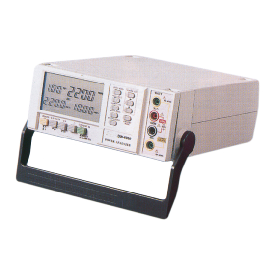
Page 11: Front Panel Description
3. FRONT PANEL DESCRIPTION Fig. 1... - Page 12 Marks : On = 1, Off = 0 AC = , DC = LCD Display Power Switch AC V/A/WATT Switch DC V/A Switch Ohm Switch Current In Switch WATT/VA/Whr Button WATT Zero Button PF/Hz Button 3-10 Peak Hold Button 3-11 Data Hold Button 3-12 Current Mode Button...
-
Page 13: Precautions & Preparations For Measurement
4. PRECAUTIONS & PREPARATIONS FOR MEASUREMENT 1) Ensure that the batteries is connected correctly to its snap terminal and placed in the battery compartment. 2) Select & push the correct Switch & button before marking measurements 3) Place the Test Lead into the proper input terminal before marking measurements. -
Page 14: Ac Watt/V/A/Pf/Hz Measurement
5-1 AC Watt/V/A/PF/Hz Measurement 1) Push the " Power switch " ( 3-2, Fig. 1 ) to " On " position. On = 1, Off = 0 2) Select the " AC V/A/WATT Switch " ( 3-3, Fig. 1). 3) Select the " Current In Switch " ( 3-6, Fig. 1 ) to the "... -
Page 15: Ac Va/V/A/Pf/Hz Measurement
6) * Connect the " LOAD " to the terminals of 3-17, 3-18, refer Fig. 2. * Connect the " POWER SOURCE " to the terminals of 3-16, 3-19, refer Fig. 2. 7) Power on the " Power Source " of the measured installation. -
Page 16: Ac Watt Hour ( Whr ) Measurement
5-3 AC Watt Hour ( Whr ) Measurement All the measuring procedures are same as the above " 5-1 AC Watt/V/A/PF/Hz Measurement " except should push the " WATT/VA/Whr Button " ( 3-7, Fig. 1 ) twice, then the display will show the Whr value along with the elapsed time. The Whr ( Watt Hour ) is the value of Watt x hour. -
Page 17: Dc Voltage, Current Measurement
5-5 DC Voltage, DC Current Measurement 1) Push the " Power switch " ( 3-2, Fig. 1 ) to " On " position. On = 1, Off = 0 2) Select the " DC V/A Switch " ( 3-4, Fig. 1 ). 3) Select the "... -
Page 18: Ohm Measurement
5-6 Ohm Measurement 1) Push the " Power switch " ( 3-2, Fig. 1 ) to " On " position. On = 1, Off = 0 2) Select the " Ohm Switch " ( 3-5, Fig. 1 ). 3) Connect red test lead to " V/Ohm Terminal " ( 3-17, Fig. 1 ). and black test lead to "... -
Page 19: Ac Watt, Va, Whr Measurement, Current Input Cooperate With Clamp-On Probe
Fig. 3 VOLTAGE INPUT 3-17 V/ohm 3-18 CURRENT INPUT 3-19 10 A CT ( 1000/5A, 100/5A ) 5-8 AC Watt, VA, Whr measurement, current input cooperate with Clamp-On Probe Other measurement procedures are same as the 5-1, 5-2, except : 1) Wire connection , ref. -
Page 20: Data Hold
Fig. 4 3-17 V/ohm VOLTAGE INPUT 3-18 Clamp-On Current Input Terminals CURRENT INPUT 3-20 ( Clamp-On Probe plugs ) 5-9 Data Hold During the measurement, Push the " Data Hold Button " ( 3-11, Fig. 1 ) will hold the display values & LCD will show the "... -
Page 21: Alarm Setting
5-11 Alarm Setting 1) Alarm setting function only for the " Watt " & " VA " display value. 2) " Alarm Set Button " ( 3-15 ) is used to set the Max., Min. alram value or set the alarm off ( display not show Max., Min. -
Page 22: Battery Replacement
6-1 Battery Replacement 1) When the LCD display show the " BAT " marker, it is necessary to replace the batteries. However, in-spec. measurement may still be made for several hours after appear low battery indicator. 2) Loose the screw, slide the Battery Cover ( 3-23, Fig. 1 ), away from the instrument and remove the batteries. -
Page 23: Rs232 Pc Serial Interface
7. RS232 PC SERIAL INTERFACE The instrument features an RS232 output via 3.5 mm Terminal ( 3-14, Fig. 1). The connector output is a 16 digit data stream which can be utilized to the user's specific application. An RS232 lead with the following connection will be required to link the instrument with the PC serial input. -
Page 24: The Address Of After Service Center
D11 & D12 Anunuciator for Display Hz = 31 DCV = 34 DCA = 36 ohm = 38 K ohm = 39 Watt = 47 Hour = 61 VA = 63 kw/hr = 65 Power factor = 54 1 = Top left display 2 = Top right display 3 = Bottom left display 4 = Bottom right display to show... - Page 25 3-11 3-15 3-10 3-14 3-16 3-17 3-18 3-19 3-12 3-13 3-22 3-21 3-23 3-20...
Need help?
Do you have a question about the DW-6090 and is the answer not in the manual?
Questions and answers