Table of Contents
Advertisement
Quick Links
1,600 point data logger, RS232, AC/DC adapter
auto calibration
DISSOLVED
OXYGEN METER
Model : DO-5519
OPERATION MANUAL
3, Hagavish st. Israel 58817 Tel: 972 3 5595252, Fax: 972 3 5594529
Your purchase of this
DISSOLVED
METER marks a step
forward for you into the
field
measurement.
Although this METER is
a complex and delicate
instrument, its durable
structure
many years of use if
p r o p e r
t e c h n i q u e s
developed. Please read
t h e
instructions
and always keep this
manual
reach.
MRC.11.21
OXYGEN
of
precision
will
allow
o p e r a t i n g
a r e
f o l l o w i n g
carefully
within
easy
mrc@mrclab.com
Advertisement
Table of Contents

Related Manuals for MRC DO-5519


Summary of Contents for MRC DO-5519
- Page 1 1,600 point data logger, RS232, AC/DC adapter auto calibration DISSOLVED OXYGEN METER Model : DO-5519 Your purchase of this DISSOLVED OXYGEN METER marks a step forward for you into the field precision measurement. Although this METER is a complex and delicate...
- Page 2 ATTENTION : Fill the Probe's Electrolyte at first. Intend to keep the DO probe under the best condition, when user receive the DIGITAL OXYGEN METER along the PROBE, it should fill the Probe's Electrolyte at first. Probe-filling Electrolyte Probe head with Diaphragm set The procedures that to fill the Probe's Electrolyte, refer the chapter 8 "...
-
Page 3: Table Of Contents
TABLE OF CONTENTS 1. FEATURES................1 2. SPECIFICATIONS..............2 3. FRONT PANEL DESCRIPTION........... 4 3-1 Display................4 3-2 Power/ESC/Send button............ 4 3-3 FUNC/HOLD button ( Send quit/ button )......▲ 3-4 REC/Enter button.............. 4 3-5 Setting/Logger button ( button )........▼... -
Page 4: Features
1. FEATURES * This Digital Oxygen Meter is supplied with a polarographic type probe with an incorporated Temp. sensor which serves for precise Dissolved Oxygen ( DO ) and Temp. measurement. * Applications for Aquarium, Medical research, Agriculture, Fish hatcheries, Laboratory, Water conditioning, Mining industry, Schools &... -
Page 5: Specifications
2. SPECIFICATIONS Display LCD size : 44 mm x 29 mm. Dual function LCD Circuit Custom one-chip of microprocessor LSI circuit. Measurement Dissolved Oxygen 0 to 20.0 mg/L ( liter ). & Range Oxygen in Air 0 to 100.0 %. Temperature 0 to 50 ℃... - Page 6 Data Output RS 232 PC serial interface. Operating 0 to 50 ℃ Temperature Operating Less than 80% RH. Humidity Power Supply 006P DC 9V battery ( Alkaline or Heavy duty type ) or DC 9V adapter input. * AC/DC power adapter is optional. Power Current Approx.
-
Page 7: Front Panel Description
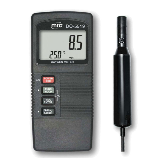
3. FRONT PANEL DESCRIPTION Fig. 1... -
Page 8: Display
Fig. 2 3-1 Display 3-2 Power/ESC/Send button 3-3 FUNC/Hold button ( Send quit/ button ) ▲ 3-4 REC/Enter button 3-5 Setting/Logger button ( button ) ▼ 3-6 Probe input socket 3-7 DC 9V adapter socket 3-8 RS-232 output terminal 3-9 Battery compartment/Cover 3-10 Battery cover screws 3-11 Oxygen Probe handle 3-12 Temperature sensor... -
Page 9: Measuring Procedure
4. MEASURING PROCEDURE 4-1 Calibration Before the measurement, the meter should be processed the following calibration procedures : 1)Connect the " Oxygen probe plug " ( 3-15, Fig. 2 ) into the " Probe input socket " ( 3-6, Fig. 1 ). 2)Power on the instrument by pushing the "... -
Page 10: Dissolved Oxygen ( Do) Measurement
The text " CAL " will flash, the upper value will count down from 30 to 0 and " End " , then show as : 20.9 26.4 ℃ % O2 The upper display will show the values exactly same as 20.9 or 20.8. ( As the oxygen in air is 20.9 % typically, so use the environment air 02 value for quick &... - Page 11 b. As for the thermal equilibrium to occur between the probe & the measurement sample must be allowed to pass, which usually amounts to a few minutes if the Temp. difference between the two is only several Celsius degrees. 4)a. In order to measure the dissolved oxygen content in any given liquid, it is sufficient to immerse the tip of the probe in the solution, making sure that velocity of the liquid coming into contact with the probe is at...
-
Page 12: Oxygen In Air ( O2) Measurement
5)Rinsed the probe accurately with normal tap water after each series of measurement. Install " Probe head protection cover " ( 3-14, Fig, 2 ) into the " Probe head " ( 3-13, Fig. 2 ). 4-3 Oxygen in Air ( O2 ) measurement After the meter be calibrated ( above procedure 4-1 ), the meter is ready for O2 ( Oxygen in air ) measurement, the display will show the indicator "... -
Page 13: Data Logger
* With the " REC " symbol on the display : a) Press the " REC button " ( 3-4, Fig. 1 ) once, the " REC MAX " symbol along with the maximum value will appear on the display. If intend to delete the maximum value, press the "... - Page 14 Manual Data Logger ( Sampling time should set to 0 second ) Press the " Logger button " ( 3-5, Fig. 1 ) once will save the data one time into the memory, at the same time the symbol " REC " will flash once and the beeper will sound.
- Page 15 5. ADVANCED SETTING PROCEDURES Before executing Advanced Setting Procedures, exit the " Hold function " and the Record " function first. * Press " Setting button " continuously at least 5 seconds to enter the setting function. * After already set the desiring value ( function ), press the "...
-
Page 16: Height Value Setting
5-1 Height Value Setting ( Lower display show " High " ) Bear in mind that the DO measurement is considered to be taken at sea level. However if the measuring environment is not at sea level ( 0 meter ), then should adjust the "... -
Page 17: Change The Temp ℃ ℉ , Unit
Use " button " ( 3-3, Fig. 1 ) and " button " ( 3-5, ▲ ▼ Fig. 1 ) to adjust the up display value until it same as the desiring Salt compensation value exactly, the unit is % Salt ( % Weight ). After select the desiring value, press the "... -
Page 18: Change The Data Logger Sampling Time
5-5 Change the data logger sampling time ( Lower display show " SP-t " ) a. Use " button " ( 3-3, Fig. 1 ) to select ▲ data logger sampling time to 0, 1, 2, 5, 10, 30, 60, 600, 1800, 3600 seconds b. -
Page 19: Code Entering For The Further Calibration Usage
5-8 Code entering for the further calibration usage ( Lower display show " CodE" ) The upper display will show 0. The code setting is used for the further technician service usage, it do not enter any new code, just press the "... -
Page 20: Rs232 Pc Serial Interface
4)If intend up load the data to the computer, then should connect the optional RS232 cable/UPCB-01 or USB cable/USB-01 and cooperate the Data Logger software ( optional, Model : SW-DL2005 ). 5)Press the " Send quit button " ( 3-3, Fig. 1 ) will escape the data sending function. - Page 21 Each digit indicates the following status : Start Word When send the upper display data = 1 When send the lower display data = 2 D12 & D11 Annunciator for Display = 01 = 02 ℃ ℉ mg/L = 07 % O2 = 06 Polarity 0 = Positive 1 = Negative...
-
Page 22: Probe Maintenance
8. PROBE MAINTENANCE User first time to use the meter : Intend to let the DO probe keep the best condition. When user receive the DIGITAL OXYGEN METER along the PROBE, it should fill the Probe's Electrolyte at first. User already use the meter for a certain period : Whenever user can not calibrate the meter properly or the meter's reading value is not... - Page 23 This sensitive diaphragm is rather delicate & is easily damaged if it comes into contact with solid objects or is subjected to blows. If the diaphragm is damaged or the electrolyte is run out, it must be replaced in the following way : Probe-filling Electrolyte, OXEL-03...
-
Page 24: Battery Replacement
9. BATTERY REPLACEMENT 1)When the upper left corner of LCD display show " ", it is necessary to replace the battery. However, in-spec. measurement may still be made for several hours after low battery indicator appears before the instrument become inaccurate. 2)Open the "... -
Page 25: Optional Accessories
10. OPTIONAL ACCESSORIES Carrying case Hard carrying case. CA-06 ( 280 x 195 x 65 mm ) RS232 cable * Isolated RS232 cable. UPCB-02 * Used to connect the meter to the computer RS232 cable * USB Computer interface cable. USB-01 * Isolated USB cable.
Need help?
Do you have a question about the DO-5519 and is the answer not in the manual?
Questions and answers