Table of Contents
Advertisement
Quick Links
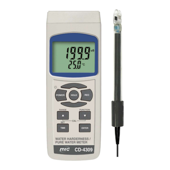
CONDUCTIVITY METER
Model : CD-4309
Your purchase of this
CONDUCTIVITY METER
marks a step forward for you
into the field of
precision measurement.
Although this meter a
complex and delicate
instrument, its durable
structure will allow
many years of use if
proper operating
techniques are
developed. Please read
the following
instructions carefully
and always keep this
manual within easy
reach.
OPERATION MANUAL
3, Hagavish st. Israel 58817 Tel: 972 3 5595252, Fax: 972 3 5594529
mrc@mrclab.com
MRC. 10.18
Advertisement
Table of Contents

Related Manuals for MRC CD-4309


Summary of Contents for MRC CD-4309
- Page 1 CONDUCTIVITY METER Model : CD-4309 Your purchase of this CONDUCTIVITY METER marks a step forward for you into the field of precision measurement. Although this meter a complex and delicate instrument, its durable structure will allow many years of use if...
-
Page 2: Table Of Contents
TABLE OF CONTENTS 1. FEATURES..................1 2. SPECIFICATIONS..................2-1 General Specifications..............2 2-2 Electrical Specifications................ 3. FRONT PANEL DESCRIPTION................4. FUNCTION SELECTION............... 5. CONDUCTIVITY/TDS MEASURING and CALIBRATION PROCEDURE..............5-1 Conductivity measurement............8 5-2 TDS ( PPM ) measurement..............5-3 Calibration................9 6. -
Page 3: Features
1. FEATURES * One meter for multi purpose operation : Conductivity, TDS (Total dissolved solids), Salt , Hardness , Resistance measurement. * Conductivity : 20 uS/ 200 uS/2 mS/20 mS/200 mS. * Salt : 0 to 12 % salt ( % weight ). * Hardness : 0 to 100,000 ppm . -
Page 4: Specifications
2. SPECIFICATIONS 2-1 General Specifications Circuit Custom one-chip of microprocessor LSI circuit. Display LCD size : 52 mm x 38 mm LCD with green backlight ( ON/OFF ). Measurement * Conductivity ( uS, mS ) Function * TDS ( Total Dissolved Solids, PPM ) * Salt ( % Weight ) * Temperature ( ℃,℉) Automatic from 0 to 60 ℃... - Page 5 Sampling Time Approx. 1 second. of Display Data Output RS 232/USB PC computer interface. * Connect the optional RS232 cable UPCB-02 will get the RS232 plug. * Connect the optional USB cable USB-01 will get the USB plug. 0 to 50 ℃. Operating Meter 0 to 60 ℃.
-
Page 6: Electrical Specifications
Optional * 1.413 mS Conductivity Standard Accessories Solution............CD-14 AC to DC 9V adapter. USB cable, USB-01. RS232 cable, UPCB-02. Data Acquisition software,SW-U801-WIN. 2-2 Electrical Specifications (23±5 ℃ ℃ ℃ ℃ ) Conductivity ( uS, mS ) Range Measurement Resolution Accuracy 20 uS 0 to 20.00 uS... - Page 7 Temperature Function Measuring Range Resolution Accuracy ℃ 0 ℃ to 60 ℃ 0.1 ℃ ±0.8 ℃ ℉ 32 ℉ to 140 ℉ 0.1 ℉ ±1.5 ℉ * @ 23±5℃ Salt Measurement 0 to 12 % salt ( % weight ). Range Resolution 0.01 % salt.
-
Page 8: Front Panel Description
3. FRONT PANEL DESCRIPTION Fig.1 3-1 Display 3-2 Power Button ( Backlight Button ) 3-3 Hold Button 3-4 REC Button 3-5 Range Button ( ▲ Button ) 3-6 Function Button ( ▼ Button ) 3-7 Time Button (SET Button) 3-8 Enter Button ( Logger Button ) 3-9 Stand 3-10 Battery Compartment/Cover 3-11 Battery Cover Screw... -
Page 9: Function Selection
4. FUNCTION SELECTION 1) Power ON the meter by pressing and holding the " Power Button " ( 3-2, Fig. 1 )for at least 1.5 seconds . Pressing the " Power Button " ( 3-2, Fig. 1 ) continuously and > 1.5 seconds again will turn off the meter. -
Page 10: Conductivity/Tds Measuring And Calibration Procedure
5. CONDUCTIVITY/TDS MEASURING and CALIBRATION PROCEDURE The meter default function are following : * The display unit is set to conductivity ( uS, mS ). * The temperature unit is set to ℃. * Temp. compensation factor is set to 2.0% per C. * Auto range. -
Page 11: Tds ( Ppm ) Measurement
Change the Temp. unit to ℉ ℉ ℉ ℉ If intend to change the Temp. unit from ℃ to ℉, please refer to chapter 10-7 page 23. Change the Temp. Coefficient Factor The default Temp. compensation factor value of the measurement solution is to 2.0% per ℃. - Page 12 3) Power on the meter by pressing " Power Button " ( 3-2, Fig. 1 ) once. 4) Hold the " Probe Handle " ( 3-18, Fig. 1) by hand and let the " Sensing head " ( 3-19, Fig. 1 ) immersed wholly into the measured solution.
- Page 13 Temprature Calibration 1) Install the " Probe Plug " ( 3-20, Fig. 1 ) into the " CD Socket " ( 3-13, Fig. 1 ). 2) Power on the meter by pressing " Power Button " ( 3-2, Fig. 1 ) once. 3) Hold the "...
-
Page 14: Salt Measuring And Calibration Procedure
6. SALT and Hardness and Resistance MEASURING and CALIBRATION 6-1 Salt measurement 1) Prepare the Probe ( CDPB-04, same probe as the conductivity measurement, refere to Fig. 1, page 6 ), install the " Probe Plug " ( 3-20, Fig. 1 ) into the " Probe Socket "... -
Page 15: Resistance Measurement
6-3 Resistance measurement 1) Prepare the Probe ( CDPB-04, same probe as the conductivity measurement, refere to Fig. 1, page 6 ), install the " Probe Plug " ( 3-20, Fig. 1 ) into the " Probe Socket " ( 3-13, Fig. 1 ). 2) Power on the meter by pressing and holding "... -
Page 16: Other Function
7. OTHER FUNCTION 7-1 Data Hold During the measurement, press the " Hold Button " ( 3-3, Fig. 1 ) once will hold the measured value & the LCD will display a " HOLD " symbol. Press the " Hold Button " once again will release the data hold function. -
Page 17: Lcd Backlight On/Off
7-3 LCD Backlight ON/OFF After power ON, the " LCD Backlight " will light automatically. During the measurement, press the " Backlight Button " ( 3-2, Fig. 1 ) once will turn OFF the " LCD Backlight ". Press the " Backlight Button " once again will turn ON the "... -
Page 18: Advanced Setting
8. ADVANCED SETTING Under do not execute the Datalogger function, press the " SET Button " ( 3-7, Fig. 1 ) continuously at least two seconds will enter the " Advanced Setting " mode. then press the " SET Button " ( 3-7, Fig. 1 ) once a while in sequence to select the eight main function, the display will show : DATE...... - Page 19 2) After set all the time value ( Year, Month, Date, Hour, Minute, Second ), press the " SET Button " ( 3-7, Fig. 1 ) once will save the time value, then the screen will jump to Sampling time " setting screen ( Chapter 10-2 ). Remark : After the time value is setting, the internal clock will run precisely even Power off if the battery is under...
- Page 20 8-4 Select the Temp. unit to ℃ ℃ ℃ ℃ or ℉ ℉ ℉ ℉ When the lower display show " T CF " 1) Use the " ▲ Button " ( 3-5, Fig. 1 ) or " ▼ Button " ( 3-6, Fig.
-
Page 21: Power Supply From Dc Adapter
Remark : During execute the " Advanced Setting " function, if press " HOLD Button " ( 3-3, Fig. 1 ) will exit the " Advanced Setting " function, the LCD will return to normal screen. 9. POWER SUPPLY from DC ADAPTER The meter also can supply the power supply from the DC 9V Power Adapter ( optional ). -
Page 22: System Reset
11. SYSTEM RESET If the meter happen the troubles such as : CPU system is hold ( for example, the key button can not be operated... ). Then make the system RESET will fix the problem. The system RESET procedures will be either following method : During the power on, use a pin to press the "... - Page 23 The 16 digits data stream will be displayed in the following format : D15 D14 D13 D12 D11 D10 D9 D8 D7 D6 D5 D4 D3 D2 D1 D0 Each digit indicates the following status : Start Word When send the upper display data = 1 When send the lower display data = 2 D12, D11 Annunciator for Display...
-
Page 24: Optional Accessories
13. OPTIONAL ACCESSORIES RS232 cable * Computer interface cable. UPCB-02 * Used to connect the meter to the computer ( COM port ). USB cable * Computer interface cable. USB-01 * Used to connect the meter to the computer ( USB port ). Data The SW-U801-WIN is a multi Acquisition...
Need help?
Do you have a question about the CD-4309 and is the answer not in the manual?
Questions and answers