
Related Manuals for MRC SL-4035SD


Summary of Contents for MRC SL-4035SD
-
Page 1: Sound Level Meter
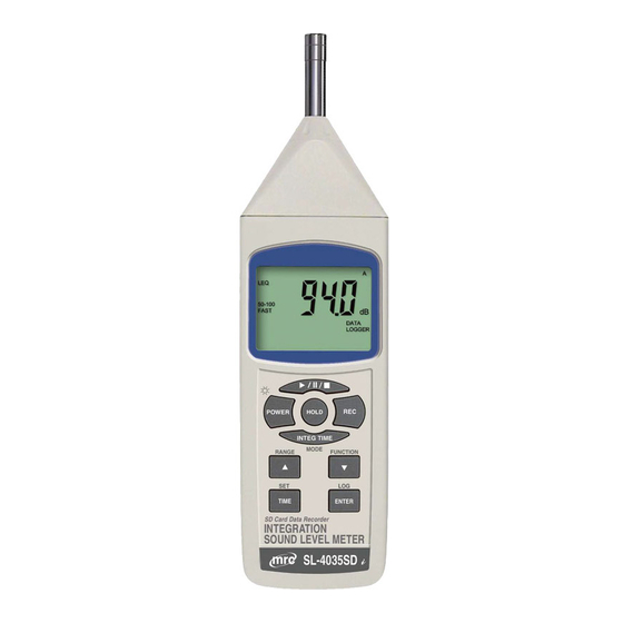
Sound Level Meter SL-4035SD Operation Manual PLEASE READ THIS MANUAL CAREFULLY BEFORE OPERATION Hagavish st. Israel 58817 Tel: 972 3 5595252, Fax: 972 3 5594529 mrc@mrclab.com MRC.8.16... -
Page 2: Table Of Contents
TABLE OF CONTENTS 1. FEATURES................2. SPECIFICATIONS..............3. FRONT PANEL DESCRIPTION..........4. MEASURING PROCEDURE............4-1 Sound Pressure Measurements (SPL)........7 4-2 Integrating Sound Level Meter Measurements (Leq)....8 4-3 Data Hold..................10 4-4 Data Record ( Max., Min. reading )..........11 5. -
Page 3: Features
1. FEATURES * Frequency and Time weighting are designed to meet IEC 61672 class 2. * The meter with programmable integrating time provides precise linearity over a wide range (100dB) and displays Leq and SPL measurements. * A & C weighting networks comply with standards. * 0.5"... -
Page 4: Specifications
2. SPECIFICATIONS Circuit Custom one-chip of microprocessor LSI circuit. Display LCD size : 52 mm x 32 mm LCD with green backlight ( ON/OFF ). SPL : Sound pressure level Measurement Leq : Equivalent Continuous Noise Level Type Measurement 30 - 130 dB. Range Resolution 0.1 dB. - Page 5 Frequency Characteristics of A & C. Weighting Network A weighting : The characteristic is simulated as "Human Ear Listing" response. Typical, if making the environmental sound level measurement, always select to A weighting. C weighting The characteristic is near the "FLAT" response.
- Page 6 Calibration VR Build in external calibration VR, easy to calibrate on 94 dB level by screw driver. * Calibrated via external SOUND CALIBRATOR ( SC-942, optional ). Calibrator B & K (Bruel & kjaer), MULTIFUNCTION ACOUSTIC CALIBRATOR Type 4226. Datalogger Auto 1 second to 3600 seconds Sampling Time...
- Page 7 Power off Auto shut off saves battery life or manual off by push button. 0 to 50 ℃. Operating Temperature Operating Less than 85% R.H. Humidity Power Supply * Alkaline or heavy duty DC 1.5 V battery ( UM3, AA ) x 6 PCs, or equivalent. * DC 9V adapter input.
-
Page 8: Front Panel Description
3. FRONT PANEL DESCRIPTION Fig. 1 3-1 Display. 3-11 Calibration VR 3-2 Power Button ( ESC, Backlight Button 3-12 RS-232 output terminal 3-3 Hold Button 3-13 DC 9V adapter socket. 3-4 REC Button 3-14 Tripod Fix Nut 3-5 Range Button ( ▲ Button ) 3-15 Battery Cover Screws 3-6 Fast/Slow Button/ Peak ( ▼... -
Page 9: Measuring Procedure
4. MEASURING PROCEDURE 4-1 Sound Pressure Measurements (SPL) In SPL mode the display shows readings of the sound pressure level. 1) Power ON the meter by pressing and holding the " Power Button " ( 3-2, Fig. 1 )for at least 1.5 seconds, the meter's default function is "... -
Page 10: Integrating Sound Level Meter Measurements (Leq)
pressing and holding the " Range Button "( 3-5, Fig. 1 ) again range will enter to the manual range ( range 1,range 2 ) and auto range in sequence ,There are still 2 manual ranges. for your choice : * Manual range 1 , 30 - 80 dB range : Display will show the text of "... - Page 11 3) Frequency weighting select How to select the frequency weighting ( A or C), the procedures please refer to chapter 7-7 page 21 . 4) According to various measuring sound source, select the Time Weighting ( Fast or Slow or PEAK Fast ) by pressing and holding the "Function ( Time Weighting Button ) "...
-
Page 12: Data Hold
6) When Integrating Time set to zero ,push " "( 3-19 Fig . 1) buttom once, meter to begin integra measurement,At the same time meter will Show " ► " Symbol at the display The run time counter will zero and begin counting While running the meter will Show "... - Page 13 b) Press the " REC Button " ( 3-4, Fig. 1 ) again, the " REC MIN " symbol along with the minimum value will appear on the display. If intend to delete the minimum value, just press the " Hold Button " ( 3-3, Fig. 1 ) once, the display will show the "...
-
Page 14: Datalogger
5. DATALOGGER 5-1 Preparation before execute datalogger function a. Insert the SD card Prepare a " SD memory card " ( 1 GB to 16 GB, optional ), insert the SD card into the " SD card socket " ( 3-18, Fig. 1). The front panel of the SD card should face against the the down case. - Page 15 the measuring data along the time information will be saved into the memory circuit. The Display will show also show text " LOGGER " when the data save into the memory circuit. Remark : How to set the sampling time, refer to Chapter 7-2, page 19.
-
Page 16: Manual Datalogger ( Set Sampling Time = 0 Second )
5-3 Manual Datalogger ( Set sampling time = 0 second ) a. Set sampling time is to 0 second Press the " REC Button ( 3-4, Fig. 1 ) once , the LCD will show the text " REC ", then press the " Logger Button " ( 3-8, Fig. -
Page 17: Sd Card Data Structure
5-5 SD Card Data structure 1) When the SD card is used into the meter, the SD card When the first time, the SD card is used into the meter, the SD card will generate a folder : SLA01 2) If the first time to execute the Datalogger, under the route SLA01\, will generate a new file name SLA01001.XLS. -
Page 18: Saving Data From The Sd Card To The Computer
6. Saving data from the SD card to the computer ( EXCEL software ) 1) After execute the Data Logger function, take away the SD card out from the " SD card socket " ( 3-18, Fig. 1 ). 2) Plug in the SD card into the Computer's SD card slot ( if your computer build in this installation ) or insert the SD card into the "... - Page 19 EXCEL graphic screen ( for example )
-
Page 21: Advanced Setting
7. ADVANCED SETTING Under do not execute the Datalogger function, press the " SET Button " ( 3-7, Fig. 1 ) continuously at least 1.5 seconds will enter the " Advanced Setting " mode. then press the " SET Button " (3-7, Fig. 1 ) once a while in sequence to select the six main function, the lower display will show : DATA……... -
Page 22: Set Sampling Time
2) After set all the time value ( Year, Month, Date, Hour, Minute, Second ), the screen will jump to " SD card Decimal character " setting screen ( Chapter 7-2 ). Remark : After the time value is setting, the internal clock will run precisely even Power is off ( The battery is under normal condition, no low battery condition ). -
Page 23: Set Beeper Sound On/Off
7-4 Set beeper sound ON/OFF When the lower display show " BEEP " 1) Use the " ▲ Button " ( 3-5, Fig. 1 ) or " ▼ Button " ( 3-6, Fig. 1 ) to select the upper value to " YES " or "... -
Page 24: Sd Memory Card Format
USA - Use " . " as the Decimal point with default. EURO - Use " , " as the Decimal point with default. 2) After select the upper text to " USA " or " EURO ", press the " Enter Button " ( 3-8, Fig. 1 ) will save the setting function with default. -
Page 25: Power Supply From Dc Adapter
2) After select the upper text to " A " or " C ", press the " Enter Button " ( 3-8, Fig. 1 ) will save the setting function with default. Note : a. The characteristic table of A, C weighting, please ref. -
Page 26: Battery Replacement
9. BATTERY REPLACEMENT 1) When the left corner of LCD display show " ", it is necessary to replace the battery. However, in-spec. measurement may still be made for several hours after low battery indicator appears before the instrument become inaccurate. 2) Loose the "... - Page 27 following format : D15 D14 D13 D12 D11 D10 D9 D8 D7 D6 D5 D4 D3 D2 D1 D0 Each digit indicates the following status : Start Word When send the upper display data = 1 When send the lower display data = 2 D12, D11 Annunciator for Display dB = 17...
-
Page 28: Calibration
11. CALIBRATION 1) Prepare the optional " SOUND CALIBRATOR ", such as " SC-941 " or " SC-942 " ( set range to 94.0 dB ). Power on the Sound Calibrator & plug calibrator output socket into the " Microphone " head ( 3-9, Fig. 1 ) of the Sound Level meter. -
Page 29: Time Weighting (Fast & Slow)
The meter ( SD card structure ) already get patent or patent pending in following countries : Germany Nr. 20 2008 016 337.4 JAPAN 3151214 TAIWAN M 358970 M 359043 CHINA ZL 2008 2 0189918.5 ZL 2008 2 0189917.0 Patent pending MRC.24.2016...
Need help?
Do you have a question about the SL-4035SD and is the answer not in the manual?
Questions and answers