Table of Contents
Advertisement
micro SD card real time data logger
CLAMP POWER ANALYZER
Model : PC-6011SD
OPERATION MANUAL
3, Hagavish st. Israel 58817 Tel: 972 3 5595252, Fax: 972 3 5594529
Your purchase of this
CLAMP POWER ANALYZER
with micro SD CARD
DATA LOGGER marks a
step forward for you
into the field of
precision measurement.
Although this meter a
complex and delicate
instrument, its durable
structure will allow
many years of use if
proper operating
techniques are
developed. Please read
the following
instructions carefully
and always keep this
manual within easy
reach.
mrc@mrclab.com
MRC. 2.23
Advertisement
Table of Contents

Related Manuals for MRC PC-6011SD


Summary of Contents for MRC PC-6011SD
- Page 1 SD card real time data logger CLAMP POWER ANALYZER Model : PC-6011SD Your purchase of this CLAMP POWER ANALYZER with micro SD CARD DATA LOGGER marks a step forward for you into the field of precision measurement. Although this meter a...
- Page 2 Caution Symbol Caution : * Risk of electric shock ! * During the measurement , do not open the cabinet. Caution : * Do not apply the overload voltage, current to the input terminal ! * Remove test leads before open the battery cover ! * Cleaning - Only use the dry cloth to clean the plastic case !
-
Page 3: Table Of Contents
TABLE OF CONTENTS 1. FEATURES....................... 2. SPECIFICATIONS.................... 3. FRONT PANEL DESCRIPTION............... 4. MEASURING PROCEDURE................4-1. The original screen................. 4-2. Entry the measurement Screen................. 4-3. The summary description of keyboard.............. 4-4.SETUP KEY description………………………………………………. 4-5 Setting function description before measuring………………………….. 5.MEASURING PROCEDURES................5-1 Single-phase power quality measurements............ -
Page 4: Features
1 FEATURES * Power quality analyzer for single-phase or balanced three-phase system. * Voltage and Current are the True RMS value. * ACV input impedance is 10 Mega ohms. * True Power(KW、MW、GW) measurement. * Apparent Power (KVA、MVA、GVA) measurement. * Reactive Power (KVAR、MVAR、GVAR) measurement. * Power Factor (PF)、Phase Angle ( ∮... -
Page 5: Specifications
2. SPECIFICATIONS 2-1. General Specifications: Circuit Custom single-chip microprocessor LSI circuit 54.6 X 32.0 mm (2.15 X 1.26 ") Display LCD Size Dot Matrix backlit LCD (128 X 64 pixels) Measurements ACV,ACA KW / KVA / KVAR / PF / KWH / KVAH / KVARH / PFH Power factor Phase angle Frequency... - Page 6 Data Output USB/RS232 RS232 computer serial interface : Computer interface * Connect the optional USB cable USB-01 will get the USB plug. *Connect the optional RS232 cable UPCB-02 will get the RS232 plug. Operating Temperature 0 to 50℃ ( 32 to 122℉ ). Operating Humidity 80% Relative Humidity max.
- Page 7 Frequency: Range Resolution Accuracy 45 to 65 Hz 0.1 Hz ±0.2 Hz Active/Apparent/Reactive POWER:PF 0.1~1.0 , PT = 1, ACV >10V,ACA > 5 A Range Resolution Accuracy 0.0 to 9.999M (W/VA/VAR) 0.1-0.001M(W/VA/VAR) ± (1.5% +20d ) Active/Apparent/Reactive POWER Hour:(WH/SH/QH): Range Resolution Accuracy 0.000K to 9.999M (WH/VAH/VARH) 0.001K-0.001M(W/VA/VAR)H...
-
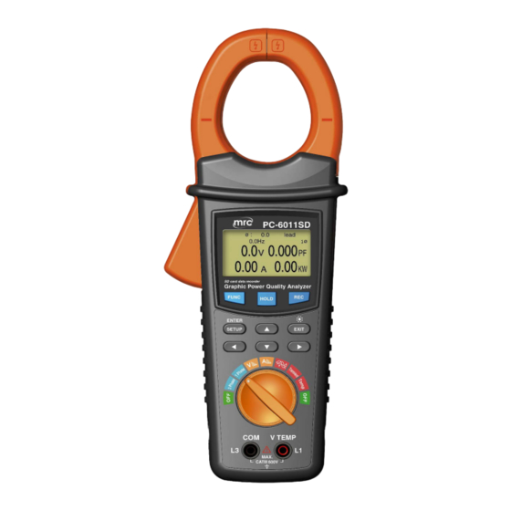
Page 8: Front Panel Description
3. FRONT PANEL DESCRIPTION Fig.1 3-1 Current Sense Jaws 3-13 Function rotary switch 3-2 Trigger 3-14 RS232 socket 3-3 Display 3-15 DC 9V power adapter socket 3-4 FUNC key button 3-16 Voltage input terminals 3-5 HOLD key button 3-17 Battery Cover/Battery compartment 3-6 REC key button 3-18 micro SD card socket 3-7 SETUP(ENTER) key button... -
Page 9: Measuring Procedure
4. MEASURING PREPARATION 4-1. The original screen 4-2. Entry the measurement Screen SCREEN 1(4-2) SCREEN 2(4-2) 1) When the bottom right corner "NO DISK" and showed flashing, it indicates the SD CARD is not inserted (as SCREEN 1) 2) The bottom left display of screen 2 will show as " SD Check "along with blinking while inserting SD CARD then disappears after several seconds that indicates the data from SD CARD has been read completed. -
Page 10: 4-4.Setup Key Description
4-4.SETUP KEY description: 4-4-1 Setting Feature List: * Folder Name: Set the expect folder name for Sd Card, the range is between WTA01 to WTA10. * File Name: Set the file name for SD CARD, It allows setting 50 filenames in this function. - Page 11 SCREEN 3(4-5) A: Press SETUP(ENTER) KEY to enter setting function screen ,total 3 page (SCREEN 1〜SCREEN 3). B: The selected item will be displayed in flashing. 4-5-1 Folder Name: Set the folder name for SD SCREEN 1(4-5-1) A:Folder Name range: WTA01 to WTA10 B:At this time Folder Name flashes,When you press or key its ...
- Page 12 C:When entering the File Name option will flash, then go to File on ◄ or ► KEY digital adjustment and flashes. press ▲ or ▼ KEY select File numbers, their numbers from "001-050" (as SCREEN 2) Remark: Press ▲ or ▼ KEY> 2 SEC then the number will quickly change * 1P201001 : 1P2 means one phase.
- Page 13 B : When you press ◄ or ► KEY> 2 Sec will show "Y or N" and "N" is flashing (as SCREEN 2), Press ▲ or ▼ KEY select "Y" and press SETUP(ENTER) KEY perform the Delete action (ex: 3P301001.XLS) will also return to SCREEN 1 or select "N"...
- Page 14 4-5-7 Beep: Set the buzzer ON or OFF SCREEN 1(4-5-7) A : When entering the Beep option and is flashing(as SCREEN1). B : When you press ◄ or ► KEY then enter the "ON" function and is flashing, press ▲ or ▼ KEY then enter the "OFF" Function and is flashing C : Press ◄...
- Page 15 B : Press ◄ or ► KEY then enter "N" option is selected and flashes, press ▲ or ▼ KEY then enter "Y" option and is now flashing C : Press ◄ or ► KEY will return to AUTO POWER OFF option and is flashing , press ▼...
- Page 16 Remark: Press ▲ or ▼ KEY> 2 SEC then the number will quickly change. C : Press ◄ or ► KEY will return to SVDP option and is flashing , press ▼ KEY then go to the next to the next option (SVDP→Decimal) 4-5-12 Decimal: set the Decimal type to USA ( .) or Euro ( , ) SCREEN 1(4-5-12) A : When entering the Decimal option and is flashing(as SCREEN1).
- Page 17 SCREEN 5(4-5-13) SCREEN 6(4-5-13) SCREEN 7(4-5-13) SCREEN 8(4-5-13) A : When entering the RS232 OUT SEL option and is flashing(as SCREEN1). B :When you press ◄ or ► KEY> 2 Sec enters SCREEN 2, press ▲ or ▼ KEY to select the desired option total 4 Page (as SCREEN 2 ~ SCREEN 5 , 1 ~ 67 item), then the digital option is flashing when press the SETUP(ENTER) KEY option content is flashing while digital options appear stationary state indicates options have been identified, while upper left corner of the LCD will...
- Page 18 4-5-14 Freq: SCREEN 1(4-5-14) SCREEN 2(4-5-14) A:When entering the Freq option and is flashing(as SCREEN 1). B:Press ◄ or ► KEY then enter "AUTO" option and is flashing, press ▲ or ▼ KEY then enter Into "50HZ" feature and showed flashes state (as SCREEN 2) C:Press ◄...
- Page 19 4-5-16 START TIME/STOP TIME:Data Record Function ,Scheduled start and end records time settings. SCREEN 1(4-5-16) SCREEN 2(4-5-16) A : When entering the START TIME or STOP TIME option and is flashing (as SCREEN 1) B : Press once ◄ or ► KEY then enter the hours adjustment options and is flashing (as SCREEN 2), then press ▲...
- Page 20 C : Press ▲ or ▼ KEY is carried (Year → Month), (Month → Date), (Date → Hour), (Hour → Minute) , (Minute → Second) and other options to adjust, in accordance with "B" item to make adjustments to the figures. D :Second option when press once ◄...
-
Page 21: Measuring Procedures
5.MEASURING PROCEDURES Single-phase power quality measurements A : Diagram SCREEN 1(5-1) SCREEN 2(5-1) Voltage and current (RMS), power factor (PF) and active power (KW) measurements... - Page 22 SCREEN 3(5-1) Maximum Demand (KW and KVA), apparent power (KVA) and reactive power (KVAR) measurements Remark: When measuring the battery is required to cancel AUTO POWER OFF function. SCREEN 4(5-1) Energy (PFh, KWh, KVAh, KVARh) measurements Remark: When measuring the battery is required to cancel AUTO POWER OFF function SCREEN 5(5-1) Graphic Phasor Diagram Display...
-
Page 23: Balanced Three-Phase Power Quality Measurements
Balanced three-phase power quality measurements A : Diagram SCREEN 1(5-2) SCREEN 2(5-2) Voltage and current (RMS), power factor (PF) and active power (KW) measurements... - Page 24 SCREEN 3(5-2) Maximum Demand(KW and KVA), apparent power(KVA) and reactive power(KVAR) measurements Remark: When measuring the battery is required to cancel AUTO POWER OFF function SCREEN 4(5-2) Energy (PFh, KWh, KVAh, KVARh) measurements Remark:When measuring the battery is required to cancel AUTO POWER OFF function SCREEN 5(5-2) Graphic Phasor Diagram Display...
-
Page 25: Maximum Demand Metering Zero
Maximum demand metering zero Press the EXIT( ) KEY (3-9, Fig.1) > 6 Sec when the MD (KW, KVA) of the measured value to zero SCREEN 1(5-3) Watt-hour zero Press the EXIT ( ) KEY (3-9, Fig.1)> 6 Sec when the "KWh", "KVAh", "KVARh" of the measured value zero SCREEN 1(5-4) -
Page 26: Voltage Harmonics Measurement
Voltage Harmonics Measurement A : Diagram SCREEN 1(5-5) SCREEN 2(5-5) SCREEN 3(5-5) -
Page 27: Current Harmonics Measurement
SCREEN 4(5-5) SCREEN 5(5-5) B : Operation Instructions: B-1 :Turn the rotary switch (3-13, Fig.1) to position B-2 :The test lead (V, COM) connected to the voltage signal, the LCD will display the waveform and harmonic chart (as SCREEN 2), press ◄ or ► KEY choose H1 ~ H50 and exhibits harmonic value, press ►... -
Page 28: Voltage And Current Waveforms Measured
SCREEN 2(5-6) SCREEN 3(5-6) SCREEN 4(5-6) SCREEN 5(5-6) B : Operation Instructions: B-1 : Turn the rotary switch (3-13, Fig.1) to position B-2 : When the input voltage signal, the system will automatically detect the correct measurement frequency measurements made w hen the input voltage when no signal, make sure the measurement frequency, at“4-5-14“option to select the measurement frequency. -
Page 29: Transient Measurement
SCREEN 1(5-7) SCREEN 2(5-7) Transient Measurement: SCREEN 1(5-8) SCREEN 2(5-8) SCREEN 3(5-8) SCREEN 4(5-8) 1) Turn the rotary switch (3-13, Fig.1) to position Transient 2) Connect the voltage signals, press REC KEY (3-6, Fig.1) event does not occur (as SCREEN 1) screen ,when the Transient Voltage ≧ 242.0V LCD will display SCREEN 2 screen (SWELL),upper right corner of the currently logged items. -
Page 30: Data Logger Function
SCREEN 1(5-9) SCREEN 2(5-9) 5-10 Data Logger Function A:When the START TIME and STOP TIME are set to 00:00 hours (as SCREEN 1) , press the REC KEY (3-6, Fig.1) once you start doing data records, more than 30,000 pen will automatically add the file name and press REC KEY (3-6, Fig.1) and once released data logging(as SCREEN 3). -
Page 31: Hard Copy Function
SCREEN 3(5-10) SCREEN 4(5-10) SCREEN 5(5-10) SCREEN 7(5-10) 5-11 Hard copy function: A:Press HOLD KEY (3-5, Fig.1) once, then press REC KEY (3-6, Fig.1) once, LCD screen will be displayed to make replication (as SCREEN 1) B:Directory name according to "Folder Name" setting,as WTA01 automatically changed BMP01, File name according to "File Name"... -
Page 32: Data Hold Function
SCREEN 3(5-11) 5-12 Data HOLD Function A:In the measurement, press HOLD KEY (3-5, Fig.1) and once the displayed value remains in the LCD, and the LCD will display the lower left corner for HOLD symbol (as SCREEN 2). B:Press HOLD KEY (3-5, Fig.1) once you release the function SCREEN 1(5-12) SCREEN 2(5-12) 5-13 EXIT(... -
Page 33: Download The Saving Data From The Micro Sd Card To The Computer ( Excel Software )
6. Download the saving data from the micro SD card to the computer ( EXCEL software ) 1) After execute the Data Logger function, take away the micro SD card out from the "micro SD card socket " ( 3-18, Fig. 1 ). 2) Plug in the micro SD card into the Computer's micro SD card slot ( if your computer build in this installation ) or insert the micro SD card into the "... - Page 34 EXCEL data screen 2 ( for example ) EXCEL data screen 3 ( for example ) EXCEL data screen 4 ( for example )
-
Page 35: Power Supply From Dc Adapter
7. POWER SUPPLY from DC ADAPTER The meter also can supply the power supply from the DC 9V Power Adapter . Insert the plug of Power Adapter into " DC 9V Power Adapter Input Socket " ( 3-15, Fig. 1 ). The meter will use the DC ADAPTER power supply . -
Page 36: Rs232 Pc Serial Output
9. RS232 PC SERIAL OUTPUT The instrument is provided an 3.5 mm dia. Phone socket ( 3-14, Fig. 1 ) for RS232 computer interface socket. The connector output is a 16 digits data stream which can be utilized to the user's specific application. A RS232 lead with the following connection will be required to link the instrument with the PC serial input. - Page 37 Each digit indicate the following status : Start Word 1 ~ 9 D12 & D11 Annunciator for Display 03=% B9 = MACA D0 = MW/Hr 31=HZ C0 = MW D1 = GW/Hr 32=DEGREE C1 = GW D2 = TW/Hr 48=K WATT C2 = TW D3 = KVA/Hr 50=ACV...
-
Page 38: Optional Accessories
10. OPTIONAL ACCESSORIES RS232 cable * Computer interface cable. UPCB-02 * Used to connect the meter to the computer ( COM port ). USB cable * Computer interface cable. USB-01 * Used to connect the meter to the computer ( USB port ). Data The SW-U811-WIN is a multi Acquisition...
Need help?
Do you have a question about the PC-6011SD and is the answer not in the manual?
Questions and answers