Table of Contents
Advertisement
Quick Links
20 Kg
SD Card real time recorder
10 ms sampling time recorder
FORCE GAUGE
Model : FG-6020SD
OPERATION MANUAL
3, Hagavish st. Israel 58817 Tel: 972 3 5595252, Fax: 972 3 5594529
Your
purchase
FORCE GAUGE marks a
step
forward
into the field of precision
measurement.
this FORCE GAUGE is a
complex
instrument,
structure will allow many
years of use if proper
operating techniques are
developed.
the following instructions
carefully and always keep
this manual within easy
reach.
mrc@mrclab.com
MRC. 1.19
of
this
for
you
Although
and
delicate
its
durable
Please
read
Advertisement
Table of Contents

Subscribe to Our Youtube Channel
Related Manuals for MRC FG-6020SD


Summary of Contents for MRC FG-6020SD
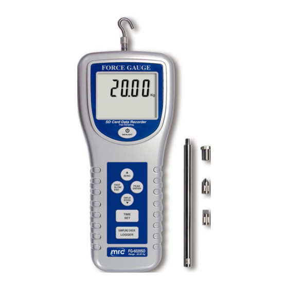
- Page 1 20 Kg SD Card real time recorder 10 ms sampling time recorder FORCE GAUGE Model : FG-6020SD Your purchase this FORCE GAUGE marks a step forward into the field of precision measurement. Although this FORCE GAUGE is a complex delicate...
- Page 2 TABLE OF CONTENTS 1 FEATURES..............1 2 SPECIFICATIONS............2 3 FRONT PANEL DESCRIPTIONS ........6 3-1 Universal Sensing Head........6 3-2 LCD Display............6 3-3 Power/BACKLIGHT Button........6 /ZERO Button............. ▲ 3-5 FAST/SLOW/ESC Button.........6 3-6 PEAK/ENTER Button..........6 3-7 DISPLAY REVERSE/ Button........▼ 3-8 TIME/SET Button...........
-
Page 3: Table Of Contents
5. DATALOGGER............. 11 5-1 Preparation before execute datalogger function..11 5-2 Normal record mode Auto Datalogger ( Set sampling time 1 second )..... ≧ 5-3 Normal record mode Manual Datalogger ( Set sampling time = 0 second )..5-4 Peak hold record mode Fast Datalogger............... - Page 4 1. FEATURES * Data record mode : Normal model or Peak hold mode. * Normal record mode : Set sampling time from 1 second to 8 hours. * Peak hold record mode : Set sampling time from 10 ms to 500 ms. * Memory capacity of normal record mode : 1 GB to 16 GB.
- Page 5 * Positive or reverse display direction select. * Full line accessories ( adapters ) are included. * Hand held & stand mounted gauges are available. * Low power consumption gives long battery life. * Build in low battery indicator. * Microprocessor circuit & exclusive load cell transducer.
- Page 6 Update time Fast Approx. 0.2 second. Slow Approx. 0.6 second. Over range Display show " - - - - " when in over Indicator range status. Normal data Auto 1 sec to 8 hour 59 min. 59 sec. record mode data @ Sampling time can set to 1 second, logger...
- Page 7 Overload Max. 30 kg. Capacity Full Scale Approx. 0.4 mm max. Deflection Zero/tare Max. full capacity. Control Transducer Exclusive load cell. Circuit Exclusive microprocessor LSI-circuit. Power Supply Alkaline or heavy duty DC 1.5 V battery ( UM3, AA ) x 6 PCs, or equivalent. DC 9V adapter input.
- Page 8 Accessories Operating manual .....1 PC. Included Flat-head adapter......1 PC. Hook adapter ......1 PC. Cone head adapter ....1 PC. Chisel head adapter ....1 PC. 120 mm extension rod....1 PC. Carrying case ......1 PC. Optional * T SD memory card ( 2 GB ) Accessories * Test stand, Model : FS-1001 * Electrical test stand, Model : FS-1002...
- Page 9 3. FRONT PANEL DESCRIPTIONS Fig. 1...
- Page 10 3-1 Universal Sensing Head 3-2 LCD Display 3-3 Power/BACKLIGHT Button /ZERO Button ▲ 3-5 Fast/SLOW/ESC Button 3-6 PEAK/ENTER Button 3-7 DISPLAY REVERSE/ Button ▼ 3-8 TIME/SET Button 3-9 LOGGER/SAMPLING CHECK Button 3-10 RS-232 output terminal 3-11 Reset terminal 3-12 DC 9V Power Adapter Input Socket 3-13 Mounting Holes/fixing Screws 3-14 Battery Cover/Compartment 3-15 Flat-head Adapter...
- Page 11 4. MEASURING PROCEDURE 4-1 Pay attention for the measurement 1) Compression measurement, the display will show the " - " mark automatically. 2) During the measurement, the SENSING HEAD along the adapter has to be on a line with measuring object. ( ref.
- Page 12 3) Rotate the SENSING HEAD is prohibited. Some certain angles between SENSING HEAD & measuring object are not allowed ( ref. Fig. 3 ). Fig. 3 4-2 Normal Measurement Power on/off Power on : Press " Power Button " ( 3-3, Fig. 1) once. Power off : During power on, press "...
- Page 13 5) Start measurement by giving force (push or pull), then the LCD will display the Average reading value. Note : * During the measurement, if intend to change the display direction, just push the " Reverse Button " ( 3-7, Fig. 1 ) once. * There are two kind sampling time of display, FAST and SLOW.
-
Page 14: Datalogger
4-4 LCD Back Light On/Off During the measurement, press the " BACKLIGHT Button " ( 3-3, Fig. 1 ) once the LCD Back Light will be ON. During the LCD Back Light ON, press the " BACKLIGHT Button " once again, the LCD Back Light will be OFF again. 4-5 Alarm beeper If the measuring value over the 20.00 Kg, the internal buzzer will sound for warning. -
Page 15: Normal Record Mode Auto Datalogger
d. Decimal format setting The numerical data structure of SD card is default used the " . " as the decimal, for example "20.6" "1000.53" . But in certain countries ( Europe ...) is used the " , " as the decimal point, for example "... -
Page 16: Normal Record Mode Manual Datalogger ( Set Sampling Time = 0 Second )
b. Pause the datalogger During execute the Datalogger function , if press the " Logger Button " ( 3-9, Fig. 1 ) once will pause the Datalogger function ( stop to save the measuring data into the memory circuit temporally ). In the same time the indicator of "... -
Page 17: Peak Hold Record Mode Fast Datalogger
Remark : During execute the Manual Datalogger, press the " ▲ Button " ( 3-4, Fig, 1 ) or " Button " ( 3-7, Fig. 1 ) to ▼ set the measuring Location no. ( 1 to 99, for example room 1 to room 99 ) to identify the measurement location , the lower Display will show P x ( x = 1 to 99 ). -
Page 18: Check Time Information
* When the peak value is got, the LCD indicator " DATA RECORD " will be disappeared . The indicator will show " PEAK " indicator only, in the same time the peak value will freeze on the Display * Following the bottom LCD will show the data record no. - Page 19 2) If the first time to execute the Datalogger, under the route FGB01\, will generate a new file name FGB01001.XLS. After exist the Datalogger, then execute again, the data will save to the FGB01001.XLS until Data column reach to 30,000 columns, then will generate a new file, for example FGB01002.XLS 3) Under the folder FGB01\, if the total files more than 99 files, will generate anew route, such as...
-
Page 20: Saving Data From The Sd Card To The Computer
6. Saving data from the SD card to the computer ( EXCEL software ) 1) After execute the Data Logger function, take away the SD card out from the " SD card socket " ( 3-20, Fig. 1 ). 2) Plug in the SD card into the Computer's SD card slot ( if your computer build in this installation ) or insert the SD card into the "... - Page 21 EXCEL data screen ( for example, peak hold record mode ) EXCEL graphic screen ( for example, graphic 1 )
-
Page 22: Advanced Setting
EXCEL graphic screen ( for example, graphic 2 ) 7. ADVANCED SETTING Under do not execute the Datalogger function, press the " SET Button " ( 3-8, Fig. 1 ) continuously at least two seconds will enter the " Advanced Setting " mode. then press the "... - Page 23 Remark : During execute the " Advanced Setting " function, if press " ESC Button " ( 3-5, Fig. 1 ) will exit the " Advanced Setting " function, the LCD will return to normal screen. 7-1 SD memory card Format When the lower display show "...
- Page 24 2) After set all the time value ( Year, Month, Date, Hour, Minute, Second ), press the " SET Button " ( 3-8, Fig. 1 ) once will save the time value, then the screen will jump to Sampling time " setting screen ( Chapter 7-3 ). Remark : After the time value is setting, the internal clock will run precisely even Power off if the battery is under...
- Page 25 7-4 Set sampling time for peak record mode When the lower display show " HSPt " 1) Use the " Button " ( 3-4, Fig. 1 ) or " Button " ▲ ▼ ( 3-7, Fig. 1 ) to adjust the value ( adjust unit is milli seconds, each step is 10 ms, setting start from 10 ms ).
- Page 26 7-6 Set beeper sound ON/OFF When the lower display show " bEEP " 1) Use the " Button " ( 3-4, Fig. 1 ) or " Button " ▲ ▼ ( 3-7, Fig. 1 ) to select the upper value to " yES " or "...
- Page 27 7-8 Decimal point of SD card setting The numerical data structure of SD card is default used the " . " as the decimal, for example "20.6" "1000.53" . But in certain countries ( Europe ...) is used the " , " as the decimal point, for example "...
-
Page 28: Power Supply From Dc Adapter
8. POWER SUPPLY from DC ADAPTER The meter also can supply the power supply from the DC 9V Power Adapter ( optional ). Insert the plug of Power Adapter into " DC 9V Power Adapter Input Socket " ( 3-12, Fig. 1 ). The meter will permanent power ON when use the DC ADAPTER power supply ( The power Button function is disable ). -
Page 29: Rs232 Pc Serial Interface
11. RS232 PC SERIAL INTERFACE The instrument has RS232 PC serial interface via a 3.5 mm terminal ( 3-10, Fig. 1 ). The data output is a 16 digit stream which can be utilized for user's specific application. A RS232 lead with the following connection will be required to link the instrument with the PC serial port. -
Page 30: Mounting Holes & Optional Test Stand
Polarity 0 = Positive 1 = Negative Decimal Point(DP), position from right to the left 0 = No DP, 1= 1 DP, 2 = 2 DP, 3 = 3 DP D8 to D1 Display reading, D1 = LSD, D8 = MSD For example : If the display reading is 1234, then D8 to D1 is : 1234 End Word... - Page 31 b. WEDGE GRIP, Model : WG-01 Wedge grip, the optional accessory to install to the base of FS-1001 be used to hold the tested material. FS-1001 WG-01 c. 150 Kg capacity ELECTRICAL TEST STAND for Force gauge Model : FS-1002-110V, FS-1002-220V * Max.
-
Page 32: Applications
13. APPLICATIONS 13-1 Electronics * Test strength of solder points and spot welds on circuit boards. * Test wire wraps on clip connection. * Test pull strength of modified wire wrap connection on posts. * Test spring clip insertion and withdrawal forces. * Pull test welds in micro-electronic devices. - Page 33 13-3 Chemical & Plastics * Test film bond strengths. * Tensile test rubber, fibers and filaments. * Measure firmness of polyurethane foam. * Test crush strength of pills (medicine) * Test peel strength of adhesives. * measure compression of ceramic compounds. * Test vacuum take-down pressure on process machines.
- Page 34 13-6 Other Industries * Measure pedal depression force in aircraft. * Test hardness of gypsum wallboard. * Test keyboard and pedal contact force of organs and pianos. * Test force to remove cover tops of aerosol cans. * Measure trigger pulling forces on firearms, hand tools etc. * Test firmness of sausages in casings.
Need help?
Do you have a question about the FG-6020SD and is the answer not in the manual?
Questions and answers