Table of Contents
Advertisement
Quick Links
Installer Manual
Programmable Thermostats
2030 1 Heat / 1 Cool Conventional
2230 Up to 2 Heat / 1 Cool
1 Specifications
4 Quick Reference 5 Installer Settings 6 System Testing
Warning
For installation by experienced service technicians only.
Caution
Possible electric shock or damage to equipment can occur.
Disconnect power before beginning installation.
This thermostat requires 24 Volt AC Power or 2 properly installed "AA" Alkaline batteries for
proper operation. When connecting 24 Volt AC Power, the batteries may be installed as a backup.
For use only as described in this manual. Any other use will void warranty.
This manual is for Installer use only - do not leave with end user.
1
SPECIFICATIONS
This thermostat is compatible with:
• Single stage conventional and heat pump systems
• Single stage heat pumps with auxiliary heat
• 250 – 750 millivolt heating only systems
• 2 wire hydronic zone systems
Electrical and Control Specifications
• Electrical Rating: 24 Volt AC
• 1 amp maximum load per terminal
• AC Power: 18 – 30 Volts AC
• DC Power: 3.0 Volt DC
(2 "AA" Alkaline Batteries Included)
• Control Range: 45° to 90° F (7° to 32° C)
• Temperature Accuracy: +/- 1° F (+/- .5° C)
or Heat Pump
Conventional or Heat Pump
Model number is located on back of thermostat.
®
Terminations
2030: Rc, Rh, W1, Y1, G, O, B, C
2230: Rc, Rh, W1/E, W2, Y1, G, O, B, L, C
E
CONOMY
S
ERIES
2030-100-01
Advertisement
Table of Contents

Related Manuals for Braeburn Economy 2030


Summary of Contents for Braeburn Economy 2030
- Page 1 ® Installer Manual CONOMY ERIES Programmable Thermostats 2030 1 Heat / 1 Cool Conventional or Heat Pump 2230 Up to 2 Heat / 1 Cool Conventional or Heat Pump Model number is located on back of thermostat. 1 Specifications 2 Installation 3 Wiring 4 Quick Reference 5 Installer Settings 6 System Testing Warning...
- Page 2 2 INSTALLATION Warning Disconnect power before beginning installation. Thermostat Location Install the thermostat approximately 5 feet (1.5m) above the floor in an area that has a good amount of air circulation and maintains an average room temperature. Avoid installation in locations where the thermostat can be affected by drafts, dead air spots, hot or cold air ducts, sunlight, appliances, concealed pipes, chimneys and outside walls.
- Page 3 2 INSTALLATION Provide Power Batteries Installed as Shown 24VAC Power Terminal (C) • Battery Power - Insert the 2 supplied “AA” type alkaline batteries into the battery compartment located in the rear housing of the thermostat. Make sure to position the Positive (+) and Negative (-) sides of the batteries correctly with the +/- symbols in the battery compartment.
- Page 4 3 WIRING Conventional and Heat Pump Systems Typical Wiring Configurations NOTE: Make sure installer system selection C ONVENTIONAL H EAT PUMP switch is properly set to CONV or HP. See Section 2. 2030 / 2230 2230 2030 / 2230 2230 Wiring Heat Only 1 Heat/...
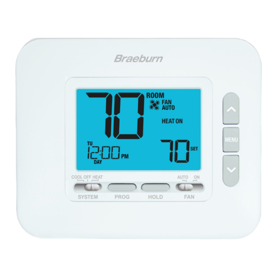
- Page 5 4 QUICK REFERENCE Thermostat and Display SYSTEM Switch ..... Selects the system you want to control PROG Button......Enters programming mode or hold for 3 seconds to enter SpeedSet mode ® BACK Button* ......Secondary function of the PROG button - Moves to previous setting HOLD Button ......
- Page 6 INSTALLER SETTINGS The Installer Settings must be properly configured in order for this thermostat to operate correctly. The Installer Settings are menu driven. The portion of these settings that do not apply to your setup will be skipped. To Enter Installer Settings Menu 1 Press and hold down the MENU button for 5 seconds.
- Page 7 5 INSTALLER SETTINGS No. Installer Setting Displayed Default Available Description of Setting Settings Available Settings HIGH HEAT Heat Setpoint 90 - 45 Select a Heat Setpoint Upper Limit of 90° to Upper Limit (32˚ to 7˚C) 45°F (32° to 7°C) Selects the upper setpoint adjustment limit that cannot be exceeded in heat mode. 45 - 90 Select a Heat Setpoint Lower Limit of 45°...
- Page 8 Montgomery, IL 60538 Installer - store this manual for future reference Braeburn Systems LLC 2215 Cornell Avenue • Montgomery, IL 60538 Technical Assistance: www.braeburnonline.com Call us toll-free: 866-268-5599 (U.S.) 630-844-1968 (Outside the U.S.) 2030-100-01 ©2022 Braeburn Systems LLC • All Rights Reserved.
Need help?
Do you have a question about the Economy 2030 and is the answer not in the manual?
Questions and answers