Braeburn ECONOMY Series User Manual
Non-programmable thermostats
Hide thumbs
Also See for ECONOMY Series:
- Installer's manual (36 pages) ,
- Installer manual (9 pages) ,
- User manual (24 pages)
Table of Contents
Advertisement
User Manual
Non-Programmable Thermostats
This manual covers the following thermostat models:
1030
1230
Read all instructions before proceeding.
1 Heat / 1 Cool Conventional
or Heat Pump
Up to 2 Heat / 1 Cool
Conventional or Heat Pump
Store this manual for future reference
®
E
CONOMY
S
ERIES
1030-110-01
Advertisement
Table of Contents

Subscribe to Our Youtube Channel
Related Manuals for Braeburn ECONOMY Series


Summary of Contents for Braeburn ECONOMY Series
- Page 1 ® User Manual CONOMY ERIES Non-Programmable Thermostats This manual covers the following thermostat models: 1030 1 Heat / 1 Cool Conventional or Heat Pump 1230 Up to 2 Heat / 1 Cool Conventional or Heat Pump Read all instructions before proceeding. Store this manual for future reference 1030-110-01...
-
Page 2: Table Of Contents
Contents 1 About Your Thermostat 4 Additional Operation Features Quick Reference - Thermostat and Display ....3 Compressor Protection ........10 2 User Settings 5 Thermostat Maintenance User Settings ............5 Battery Replacement ........... 11 Table of User Settings ..........6 Thermostat Cleaning ........... 11 Resetting Service Reminders ........6 Service Reminders ........... -
Page 3: About Your Thermostat
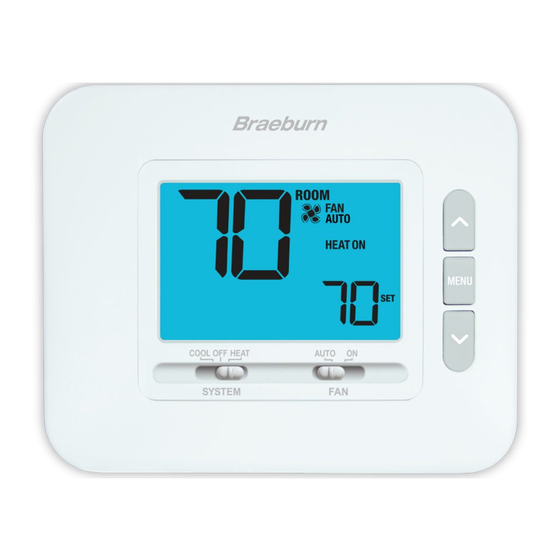
1 About Your Thermostat User Manual... - Page 4 Thermostat and Display SYSTEM Switch ..... Selects the system you want to control FAN Switch ......Selects the system fan mode Up / Down Arrow Buttons ..Increases or decreases settings MENU Button ......Used to access thermostat User setting mode Room Temperature ....
-
Page 5: User Settings
2 User Settings User Settings allow you set and customize various thermostat features. To access the User Settings, press and release the MENU button to display the first User Setting. Press the buttons to change the value for the displayed User Setting. After your desired setting is displayed, press MENU to advance to the next User Setting. -
Page 6: Table Of User Settings
Table of User Settings No. User Setting Displayed Default Available Description of Setting Settings Available Settings N0 Select to keep message displayed CLR Reset SERVICE FILTER Message Y Select to remove message and reset timer [Only appears if the service filter time interval has expired] If a service filter time interval was selected in setting 2, the thermostat will display a SERVICE FILTER message once that time interval is reached. -
Page 7: Operating Your Thermostat
3 Operating Your Thermostat Setting the SYSTEM Control Mode The System Control has 4 modes of operation – COOL, OFF, HEAT, and EMER (1230 only). The mode can be selected by moving the SYSTEM switch to the appropriate mode. COOL Only your cooling system will operate. Heating and cooling systems are off. -
Page 8: Temperature Adjustment
Temperature Adjustment Press to adjust the current set temperature. System Status and Maintenance Indicators Status indicators are messages or symbols that appear in the display to let you know what function your system is currently performing. They are also used to inform you of various service and maintenance functions. ROOM HEAT ON The heating system is running. - Page 9 System Status and Maintenance Indicators (continued) ROOM AUTO Setpoint temperature has reached its COOL upper or lower limit maximum. HI TEMP Room temperature has risen above the display range. Cooling will still operate to help lower temperature. ROOM AUTO LO TEMP Room temperature has fallen below the COOL ON display range.
-
Page 10: Additional Operation Features
System Status and Maintenance Indicators (continued) ROOM AUTO If batteries are installed and they become low, the battery symbol appears in the display. HEAT When the batteries become critically low, the battery symbol will flash (see “Changing the Batteries” in section 5). 4 Additional Operating Features Compressor Protection This thermostat includes an automatic compressor protection delay to avoid potential damage to your system... -
Page 11: Thermostat Maintenance
5 Thermostat Maintenance Changing the Batteries Depending on your installation, this thermostat may be equipped with ROOM two (2) “AA” type alkaline batteries. AUTO If batteries are installed and they become low, the battery symbol appears HEAT in the display. When the batteries become critically low, the battery symbol will flash. - Page 12 • Or write us: Braeburn Systems LLC 2215 Cornell Avenue Montgomery, IL 60538 Braeburn Systems LLC 2215 Cornell Avenue • Montgomery, IL 60538 Technical Assistance: www.braeburnonline.com Call us toll-free: 866-268-5599 (U.S.) 630-844-1968 (Outside the U.S.) 1030-110-01 ©2022 Braeburn Systems LLC • All Rights Reserved.
Need help?
Do you have a question about the ECONOMY Series and is the answer not in the manual?
Questions and answers