Table of Contents
Advertisement
Quick Links
Advertisement
Table of Contents

Related Manuals for Dahua ASC2102B-T


Summary of Contents for Dahua ASC2102B-T
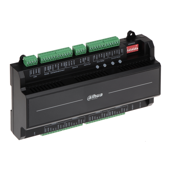
- Page 1 Two-door Sub Access Controller User’s Manual V1.0.2...
-
Page 2: Cybersecurity Recommendations
Cybersecurity Recommendations The necessary measures to ensure the basic cyber security of the platform: Use Strong Passwords Please refer to the following suggestions to set passwords: The length should not be less than 8 characters. Include at least two types of characters; character types include upper and lower case letters, numbers and symbols. - Page 3 It is recommended to regularly detect security vulnerabilities in the operating system and third- party components, and apply official patches in time. Security Audit Check online users: It is recommended to check online users irregularly to identify whether there are illegal users logging in.
-
Page 4: Foreword
Foreword General This document elaborates on structure, installation, interface and wiring of two-door sub access controller. Safety Instructions The following categorized signal words with defined meaning might appear in the Manual. Signal Words Meaning Indicates a high potential hazard which, if not avoided, will result in death or serious injury. - Page 5 There still might be deviation in technical data, functions and operations description, or errors in print. If there is any doubt or dispute, please refer to our final explanation. Upgrade the reader software or try other mainstream reader software if the Guide (in PDF format) ...
-
Page 6: Important Safeguards And Warnings
Important Safeguards and Warnings The following description is the correct application method of the device. Please read the manual carefully before use, in order to prevent danger and property loss. Strictly conform to the manual during application and keep it properly after reading. Operating Requirement Please don’t place and install the device in an area exposed to direct sunlight or near heat ... -
Page 7: Table Of Contents
Table of Contents Cybersecurity Recommendations ........................I Foreword ................................III Important Safeguards and Warnings ......................V 1 Overview ................................ 1 2 Packing List ..............................2 3 Installation Guide ............................3 System Structure ..................................3 External Dimension ................................... 3 Device Installation ..................................4 Disassembly .................................... -
Page 8: Overview
Overview As a sub main controller of main access controller, two-door sub access controller is matched with main access controller and is widely used in banks, safe places, and more. Its rich functions are as follows: Adopt sliding rail type and lock type installation, convenient installation and maintenance. ... -
Page 9: Packing List
Packing List Before installation, please check according to the table below. Table 2-1 Name Quantity Access controller Installation positioning drawing Accessory kit (screw, expansion pipe and wiring terminal) Quick start guide Certificate of qualification... -
Page 10: Installation Guide
Installation Guide System Structure External Dimension The unit is mm. -
Page 11: Device Installation
Device Installation There are two installation modes. Mode 1: fix the whole device onto the wall with screws. Mode 2: install U-shaped guide rail, and hang the whole device onto the wall (U-shaped guide rail is a self-bought fitting). Mode 1 Installation diagram is shown below. -
Page 12: Disassembly
Mode 2 Installation diagram is shown below. Fix the U-shaped guide rail onto the wall with screws. Buckle the upper rear part of the device into upper groove of U-shaped guide rail. Push the snap joint at the bottom of the device upwards. The installation is completed when you hear the fitting sound. -
Page 13: Wiring Description
Wiring Description Device wiring diagram is shown below. Interfaces are described in the table below. Table 3-1 Interface Description Interface Description CAN bus Not available at present External extension module Entry reader of door 1 Door sensor and exit button Exit reader of door 1... -
Page 14: Wiring Description Of Can Bus
Interface Description Interface Description External alarm input Entry reader of door 2 External alarm output Exit reader of door 2 Lock control output Reboot Internal alarm output DC 12V power interface Address code/transmission rate Indicator lights are described in the table below. Table 3-2 Description Lock status indicator... -
Page 15: Wiring Description Of External Alarm Input
Interface Wiring Terminal Description PUSH1 Exit button of door 1 Door sensor input of door 1 PUSH2 Exit button of door 2 Door sensor input of door 2 Shared by exit button of door 2 and door sensor input of door 2 3.5.3 Wiring Description of External Alarm Input Table 3-5 Interface... -
Page 16: Wiring Description Of Lock
Table 3-6 Interface Wiring Terminal Description External alarm output interfaces are able to External alarm output connect audible and visual sirens. 3.5.5 Wiring Description of Lock Support 2 groups of lock control outputs; serial numbers after the terminals represent corresponding doors. -
Page 17: Wiring Description Of Internal Alarm Output
Table 3-7 Interface Wiring Terminal Description COM1 Lock control of door 1 Lock control output COM2 Lock control of door 2 3.5.6 Wiring Description of Internal Alarm Output Corresponding wiring terminals of internal alarm control output are shown below. Table 3-8 Interface Wiring Terminal Description... -
Page 18: Dip Switch
DIP Switch Set device number and speed with DIP switch. DIP switch is shown in the table below. Table 3-11 Description Function Set device number with binary system. The left is the lowest order. For example: Device Number 1~5 Binary representation 00110 corresponds to 6 in decimal system. Set the speed. -
Page 19: Reboot
Table 3-12 Function Description Set device number with binary system. The left is the lowest order. For example: Device 1~5 Number Binary representation 00110 corresponds to 6 in decimal system. Set the speed. All of them are at the bottom , transmission speed is 50kb/s. -
Page 20: Technical Parameters
Technical Parameters Parameter Specification Processor 32-bit ARM processor Storage Capacity Max User 20,000 Max Record 30,000 Communication Port of Reader Wiegand,RS485 Communication Port Quantity of Connected Reader 4 groups Working Power Rated power 10V~15V DC, rated current 0.75A Real-time Monitoring Support Fire Alarm Linkage Support...
Need help?
Do you have a question about the ASC2102B-T and is the answer not in the manual?
Questions and answers