Table of Contents
Advertisement
Quick Links
Advertisement
Table of Contents

Subscribe to Our Youtube Channel
Related Manuals for Dahua ASI7223X-A


Summary of Contents for Dahua ASI7223X-A
- Page 1 Face Recognition Terminal User’s Manual V1.0.0...
-
Page 2: Foreword
Foreword General This manual introduces the installation and basic operation of the Face Recognition Terminal (hereinafter referred to as "terminal"). Safety Instructions The following categorized signal words with defined meaning might appear in the manual. Signal Words Meaning Provides additional information as the emphasis and supplement to the text. NOTE Revision History Version... -
Page 3: Important Safeguards And Warnings
Important Safeguards and Warnings This Chapter describes the contents covering proper handling of the terminal, hazard prevention, and prevention of property damage. Read these contents carefully before using the terminal, comply with them when using, and keep it well for future reference. Operation Requirement ... -
Page 4: Table Of Contents
Table of Contents Foreword ..............................I Important Safeguards and Warnings ..................... II 1 Overview ..............................1 Introduction ........................... 1 Features ............................1 Dimension and Component ......................2 2 Installation .............................. 4 Cable Connections ........................4 Installation ............................. 6 3 System Operation ..........................8 Button Description ......................... - Page 5 3.10.1 USB Export ........................26 3.10.2 USB Import ........................27 3.10.3 USB Update ........................27 3.10.4 Features .......................... 27 3.10.5 Result Feedback ......................30 3.11 Record ............................32 3.12 Auto Test............................ 33 3.13 System Info ..........................34 4 Web Operation ............................. 35 Initialization ..........................
- Page 6 5.2.2 Manual Add ........................59 Add Users ............................ 60 5.3.1 Card Type Selection ......................61 5.3.2 Add One User ........................62 Add Door Group .......................... 63 Access Permission Configuration ....................65 5.5.1 Giving Permission by Door Group ..................65 5.5.2 Giving Permission by User ID................... 67 Appendix 1 Cybersecurity Recommendations ...................
-
Page 7: Overview
Overview Introduction The terminal is an access control panel that supports unlock through faces, passwords, and supports unlock through their combinations. Features Support face unlock and password unlock; unlock by period With face detection box; the largest face among faces that appear at the same time is ... -
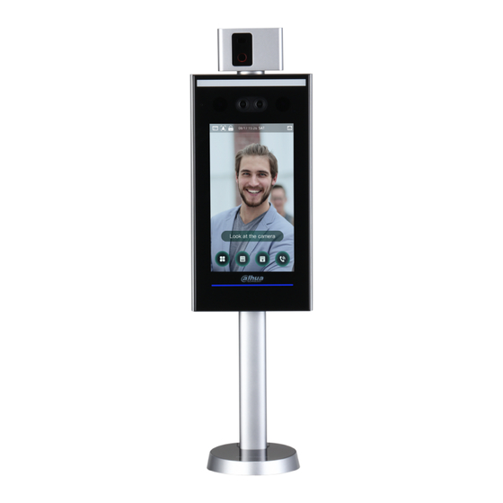
Page 8: Dimension And Component
Dimension and Component Figure 1-1 Dimensions and components (1) (mm [inch]) Table 1-1 Component description (1) Name Dual camera IR light Phototransistor White fill light Display Overview 2... - Page 9 Figure 1-2 Dimensions and components (2) (mm [inch]) Table 1-2 Component description (2) Name Dual camera IR light Phototransistor White fill light Display Overview 3...
-
Page 10: Installation
Installation Cable Connections The terminal needs to be connected to devices like sirens, readers, and door contacts. For cable connection, see Table 2-1. Table 2-1 Port description Cable Port Cable name Description color Negative electrode of external reader power Black RD–... - Page 11 Cable Port Cable name Description color White and ALARM1_NO Alarm 1 normally open output port. White and ALARM1_COM Alarm 1 common output port. orange White and DOOR2_NO Gate machine control normally open port. blue White and DOOR2_COM Gate machine control common port. gray CON2 White and...
-
Page 12: Installation
Installation Figure 2-1 Installation of the 7-in terminal Table 2-2 Component description (2) Name Ornamental cover M5 screw Waterproof silica gel plug Terminal Cable Figure 2-2 Installation of the 10-in terminal Table 2-3 Component description (3) Name Terminal Ornamental cover M5 screw Cable Waterproof silica gel plug... - Page 13 Installation Procedure Step 1 Thread cable through the turnstile. Step 2 Put the waterproof silica gel plug on the cable. Step 3 Fix the terminal onto the turnstile with M5 screw. Connect cables for terminal. See "2.1 Cable Connections." Step 4 Apply sealant to gaps between the waterproof silica gel plug and turnstile.
-
Page 14: System Operation
System Operation Button Description Table 3-1 Button description Button Description Go to the first page. Go to the last page. Go to the previous page. Go to the next page. Go to the previous menu. Go to the next menu. Initialization Administrator password and an email should be set the first time the terminal is turned on;... -
Page 15: Standby Interface
The administrator password can be reset through the email address you entered if the administrator forgets the administrator password. The password should consist of 8 to 32 non-blank characters and contain at least two types of characters among upper case, lower case, number, and special character (excluding ' "... -
Page 16: Unlocking Methods
Table 3-2 Homepage description Description Unlock methods: Card, face, and password. Date & Time: Current date and time is displayed here. Network status and battery status are displayed here. Main menu icon. Only the administrator can enter the main menu. Password unlock icon. -
Page 17: Main Menu
Main Menu Administrators can add users of different levels, set access-related parameters, do network configuration, view access records and system information, and more in the main menu. Step 1 on the standby interface. The Administrator Login interface is displayed. Different modes support different unlock methods, and the actual interface shall prevail. Figure 3-3 Administrator login Step 2... -
Page 18: Terminal User Management
Figure 3-4 Main Menu Terminal User Management You can add new users, view user lists, admin lists, and modify the administrator password on the User interface. 3.6.1 Adding New Users You can add new users by entering user IDs, names, importing fingerprints, face images, cards, passwords, selecting user levels, and more. - Page 19 Figure 3-5 New User Info Step 2 Configure parameters on the interface. See Table 3-3. Table 3-3 New user parameter description Parameter Description You can enter user IDs. The IDs can be numbers, letters, and their User ID combinations, and the maximum length of the ID is 32 characters. You can enter names with at most 32 characters (including numbers, symbols, Name and letters).
-
Page 20: Viewing User Information
Parameter Description Holiday You can set a holiday plan in which the user can unlock the door. For detailed Plan holiday plan settings, see the configuration manual. Valid Date You can set a period during which the unlocking information of the user is valid. There are six levels: General: General users can unlock the door normally. -
Page 21: Unlock
start time and end time of a holiday group, and then users can only unlock the door in the periods that you set. You can enter names with 32 characters (including numbers, symbols, and letters). Tap save the holiday group name. 3.7.1.3 Holiday Plan You can add holiday groups into holiday plans. - Page 22 The Element (Multiple Choice) interface is displayed. See Figure 3-6. Figure 3-6 Element (multiple choice) Step 2 Select unlock mode(s). Tap a selected unlock mode again, the unlock mode will be deleted. Step 3 Select a combination mode. + And means "and". For example, if you selected card + FP, it means, to unlock ...
- Page 23 3.7.2.2 Unlock by Period Doors can be unlocked through different unlock modes in different periods. For example, in period 1, the door can only be unlocked through card; and in period 2, doors can only be unlocked through fingerprints. Step 1 Select Assess >...
- Page 24 Step 1 Select Assess > Unlock Mode > Group Combination. The Group Combination Config interface is displayed. See Figure 3-8. Figure 3-8 Group Combination Step 2 to create a group. The Add Group interface is displayed. See Figure 3-9. Figure 3-9 Add a group System Operation 18...
-
Page 25: Alarm Configuration
Table 3-4 Group parameter Parameter Description Add users to the newly created group. Tap User List. The User List interface is displayed. User List , and then enter a user ID. to save the settings. Unlock Mode There are two options: PWD and Face. Valid users are the ones that have unlock authority. -
Page 26: Door Status
Table 3-5 Parameters on the alarm interface Parameter Description If a person unlocks the door with the identity checked by the access controller, but when the person gets out without getting the identity checked by the access controller, an alarm will be triggered and the Anti-passback person will have no authority to unlock the door any more. - Page 27 Figure 3-11 IP address configuration Table 3-6 IP configuration parameters Parameter Description The IP address, subnet mask, and gateway IP address should be on IP Address/Subnet Mask/Gateway IP the same network segment. After configuration, tap to save the Address configurations. DHCP (Dynamic Host Configuration Protocol).
-
Page 28: Serial Port Settings
Table 3-7 Active register Name Parameter Server IP Address IP address of the managing platform. Port Port number of the managing platform. Device ID Subordinate device number on the managing platform. 3.8.1.3 Wi-Fi You can connect the access controller to the network through Wi-Fi if the access controller has Wi-Fi function. -
Page 29: Wiegand Configuration
3.8.3 Wiegand Configuration Select Wiegand Input or Wiegand Output according to the entering direction and exiting direction. Select Connection > Wiegand, and then the Wiegand interface is displayed. See Figure 3-13. Figure 3-13 Wiegand Select Wiegand Input when an external card swipe mechanism is connected to the ... -
Page 30: Face Parameter
When you select Network Time Protocol (NTP), you need to configure the following parameters. You need to enable the NTP Check function first. Server IP Address: enter the IP address of the time server, time of the terminal will be synchronized with the time server. ... -
Page 31: Fill Light Mode Setting
Name Description This function prevents people from unlocking by human face images Anti-fake Threshold or face models. The larger the value is, the more difficult face images can unlock the door. The recommended value range is above 80. 3.9.3 Fill Light Mode Setting You can select fill light modes according to your needs. -
Page 32: Usb
3.10 Make sure that the USB is inserted before exporting user information and updating. During exporting or updating, do not pull out the USB or do other operations; otherwise the exporting or updating will fail. You need to import information from one terminal to the USB before using USB to import ... -
Page 33: Usb Import
3.10.2 USB Import Only data in the USB that was exported from one terminal can be imported into another terminal. Step 1 Select USB > USB Import. The USB Import interface is displayed. See Figure 3-16. Figure 3-16 USB Import Step 2 Select the data type that you want to import. - Page 34 Figure 3-17 Features Table 3-10 Feature description Parameter Description Privacy Setting See "3.10.4.2 Privacy Setting" for details. If the third party card reader needs to be connected to the terminal through the wiegand output port, you need to enable the Card No. Card No.
- Page 35 3.10.4.2 Privacy Setting Figure 3-18 Privacy setting Table 3-11 Features Parameter Description PWD Reset If the PWD Reset Enable function is enabled, you can reset the password. Enable The PWD Reset function is enabled by default. Hypertext Transfer Protocol Secure (HTTPS) is a protocol for secure communication over a computer network.
-
Page 36: Result Feedback
3.10.5 Result Feedback You can select a result feedback mode as needed. Mode 1 Figure 3-19 Mode 1 System Operation 30... - Page 37 Mode 2 Figure 3-20 Mode 2 Mode 3 Figure 3-21 Mode 3 System Operation 31...
-
Page 38: Record
Mode 4 Figure 3-22 Mode 4 3.11 Record You can query all unlocking records. System Operation 32... -
Page 39: Auto Test
Figure 3-23 Search punch records 3.12 Auto Test When you use the terminal for the first time or when the terminal malfunctioned, you can use auto test function to check whether the terminal can work normally. Do actions according to the prompts. -
Page 40: System Info
Figure 3-24 Auto test When you select Auto Test, the terminal will guide you to do all the auto tests. 3.13 System Info You can view data capacity, device version, and firmware information of the terminal on the System Info interface. System Operation 34... -
Page 41: Web Operation
Web Operation The terminal can be configured and operated on the web. Through the web you can set network parameters, video parameters, and terminal parameters; and you can also maintain and update the system. Initialization You need to set a password and an email address before logging in to the web for the first time. Step 1 Open IE web browser, and enter the IP address (the default address is 192.168.1.108) of the terminal in the address bar, and then press Enter. -
Page 42: Login
Figure 4-2 Auto Test Step 4 You can decide whether to select Auto Check or not. It is recommended that Auto Check be selected to get the latest program in time. Step 5 Click Next. The configuration is finished. See Figure 4-3. Figure 4-3 Finished configuration Step 6... -
Page 43: Reset The Password
press Enter. Figure 4-4 Login Step 2 Enter the username and password. The default administrator name is admin, and the password is the login password after initializing the terminal. Modify the administrator regularly and keep it properly for the sake of security. ... - Page 44 Figure 4-5 Tips Step 2 Read the tips. Step 3 Click OK. The Reset Password interface is displayed. Figure 4-6 Reset Password Step 4 Scan the QR code on the interface, and you will get the security code. At most two security codes will be generated by scanning the same QR code. To ...
-
Page 45: Alarm Linkage
Please use the security code within 24 hours after you receive it. Otherwise, it will become invalid. If wrong security codes are entered for consecutive five times, the administrator will be frozen for five minutes. Step 5 Enter the security code you have received. Step 6 Click Next. - Page 46 Figure 4-8 Modifying alarm linkage parameter Table 4-1 Alarm linkage parameter description Parameter Description Alarm Input You cannot modify the value. Keep it default. Name Enter a zone name. There are two options: NO and NC. Alarm Input Type If alarm input type of the alarm device you purchased is NO, then you should select NO;...
-
Page 47: Alarm Log
4.4.2 Alarm Log You can view the alarm type and time range in the Alarm Log interface. Step 1 Select Alarm Linkage > Alarm Log. The Alarm Log interface is displayed. See Figure 4-9. Figure 4-9 Alarm log Step 2 Select a time range and alarm type, and then click Query. -
Page 48: Video Setting
Figure 4-11 Data capacity Video Setting You can set parameters including data rate, image parameters (brightness, contrast, hue, saturation, etc.), and exposure on the Video Setting interface. 4.6.1 Data rate For data rate descriptions, see Table 4-2. Figure 4-12 Data rate Table 4-2 Data rate parameter description Parameter Description... -
Page 49: Image
Parameter Description The rate at which consecutive frames appear on a display. The Frame Rate frame rate range is 1–25fps. The number of bits that are conveyed or processed per unit of Bit Rate time. There are five options: 1.75Mbps, 2Mbps, 4Mbps, 6Mbps, and 8Mbps. -
Page 50: Exposure
Parameter Description Close: without modes. Auto: The system automatically adjusts scene modes. Sunny: In this mode, image hue will be reduced. Scene Mode Night: In this mode, image hue will be increased. Sunny is selected by default. Day/Night mode decides the working status of the fill light. -
Page 51: Motion Detection
Parameter Description When you select Outdoor in the Anti-flicker drop-down list, you can select Shutter Priority as the exposure mode. Exposure modes of different devices might vary, and the actual product shall prevail. You can select from: Auto: The terminal will automatically adjust brightness of images. ... -
Page 52: Volume Setting
Figure 4-14 Motion detection Step 2 Press and hold the left mouse button, and then drag the mouse in the red area. The Motion Detection area is displayed. See Figure 4-15. The red rectangles are motion detection area. The default motion detection range is all the rectangles. -
Page 53: Image Mode
Figure 4-16 Volume setting 4.6.6 Image Mode There are three options: indoor, outdoor and other. Select Indoor when the terminal is installed indoors; select Outdoor when the terminal is installed outdoors; and select Other when the terminal is installed at places with backlights like corridors and hallways. Figure 4-17 Image mode Face Detect... - Page 54 Figure 4-18 Face detect Step 2 Configure parameters. See Table 4-5. Table 4-5 Face detect parameter description Parameter Description Face Recognition The larger the value is, the higher the accuracy will be. Threshold Max. Angle of Face The larger the angle is, the wider range of the profiles will be Recognition recognized.
-
Page 55: Network Setting
Parameter Description is invalid face prompt interval. Pupillary distance is the pixel value of the image between the centers of the pupils in each eye. You need to set an appropriate value so that the access controller can recognize faces as needed. The value Pupillary Distance changes according to the face sizes and the distance between faces and the lens. - Page 56 Figure 4-19 TCP/IP Step 2 Configure parameters. Table 4-6 TCP/IP Parameter Description IP Version There is one option: IPv4. MAC address of the is displayed. terminal Static Set IP address, subnet mask, and gateway address manually. DHCP After DHCP is enabled, IP address, subnet mask, and gateway address cannot be configured.
-
Page 57: Port
Step 3 Click OK to complete the setting. 4.8.2 Port Set the maximum connections clients that the terminal can be connected to and port numbers. Step 1 Select Network Setting > Port. The Port interface is displayed. Step 2 Configure port numbers. See the following table. Except max connection, you need to reboot the terminal to make the configuration effective after modifying values. - Page 58 mobile app. You do not need to apply dynamic domain name, do port mapping or do not need transit server. If you are to use P2P, you must connect the terminal to external network; otherwise the terminal cannot be used. Figure 4-20 Step 1 Select Network Setting >...
-
Page 59: Safety Management
Safety Management 4.9.1 IP Authority Figure 4-21 IP authority Select a cyber security mode as needed. 4.9.2 Systems 4.9.2.1 System Service There are four options: SSH, PWD Reset Enable, CGI, and HTTPS. Refer to "3.10.4 Features” to select one or more than one of them. The system service configuration done on the web page and the configuration on the Features interface of the terminal will be synchronized. -
Page 60: User Management
4.9.2.2 Create Server Certificate Click Create Server Certificate, enter needed information, click Save, and then the terminal will reboot. 4.9.2.3 Download Root Certificate Step 1 Click Download Root Certificate. Select a path to save the certificate on the Save File dialog box. Step 2 Double-click Root Certificate that you have downloaded to install the certificate. -
Page 61: Configuration Management
Figure 4-24 Maintenance Select the auto reboot date and time. The default reboot time is at 2 O’clock in the morning on Tuesday. Click Reboot Device, the terminal will reboot immediately. Click OK, the terminal will reboot at 2 O’clock in the morning every Tuesday. 4.9.5 Configuration Management When more than one terminal needs the same configuration, you can configure parameters for them by importing or exporting configuration files. -
Page 62: Online User
4.9.8 Online User You can view username, IP address, and user login time on the Online User interface. See Figure 4-26. Figure 4-26 Online user 4.10 System Log You can view and backup the system log on the System Log interface. See Figure 4-27. Figure 4-27 System log Web Operation 56... -
Page 63: Query Logs
4.10.1 Query Logs Select a time range, type, click Query, and logs meet the conditions will be displayed. 4.10.2 Backup Logs Click Backup to back up the logs displayed. 4.11 Admin Log Enter Admin ID on the Admin Log interface, click Query, and then you will see the administrator’s operation records. -
Page 64: Smartpss Configuration
SmartPSS Configuration You can do access permission configuration to a single door or door groups through the Smart PSS client. For detailed configurations, see the SmartPSS user manual. Smart PSS interfaces might vary with versions, and the actual interface shall prevail. Login Install the Smart PSS (the username is admin, and the password is admin123 by default), double-click... -
Page 65: Manual Add
Figure 5-2 Auto search Step 1 Click Auto Search, enter the network segment, and then click Search. A list will be displayed. Step 2 Select terminals that you want to add to the Smart PSS, and then click Add, the Login information dialog box will be displayed. -
Page 66: Add Users
Figure 5-4 Manual add Step 1 Click Add on the Devices interface, and the Manual Add interface will be displayed. Step 2 Enter the Device Name, select a method to add, enter the IP/Domain Name, Port number (37777 by default), Group Name, User Name, and Password. Step 3 Click Add, and then you can see the added terminal on the Devices interface. -
Page 67: Card Type Selection
Figure 5-5 5.3.1 Card Type Selection Card types must be the same as card issuer types, otherwise card numbers cannot be read. On the Access interface, click , then click the IC or ID card icon, and then select a card type. -
Page 68: Add One User
Figure 5-6 Access Figure 5-7 Setting card type 5.3.2 Adding One User You can add users one by one. , and then enter user’s information. Click On the Access interface, click , then click Finish to complete the user adding. See Figure 5-8 and Figure 5-9. SmartPSS Configuration 62... -
Page 69: Add Door Group
Figure 5-8 Access Figure 5-9 Add user Adding Door Group You can manage doors by grouping doors. SmartPSS Configuration 63... - Page 70 On the Access interface, click , click Add, enter door group name, select a time zone. Click Finish to complete the user adding. See Figure 5-10 and Figure 5-11. Figure 5-10 Access SmartPSS Configuration 64...
-
Page 71: Access Permission Configuration
Figure 5-11 Add door group Access Permission Configuration You can do access permission configuration. There are two options: door group access permission and user access permission. Information of users who are given access permission in the Smart PSS and terminals will be synchronized. 5.5.1 Giving Permission by Door Group Select a door group, add users to the door list, and then users on the door list get access permissions of all doors on the door list. - Page 72 Figure 5-12 Access Figure 5-13 User select Step 1 On the Access interface, click , click Add, click Door Group Permission. Step 2 Click . Select user department in the Dropdown list, or enter user ID/Name, and SmartPSS Configuration 66...
-
Page 73: Giving Permission By User Id
then search users. Select users from the users you found. Step 3 Click Finish to complete the configuration. Users without user ID cannot be found. 5.5.2 Giving Permission by User ID You can give access permission to a user by selecting a user, and then select door groups for the user. - Page 74 Figure 5-15 Select door group Step 1 On the Access interface, click Step 2 Click . The Select Door Group interface is displayed. Step 3 Select user department in the dropdown list, or enter user ID/Name, and then select a door list.
-
Page 75: Appendix 1 Cybersecurity Recommendations
Appendix 1 Cybersecurity Recommendations Cybersecurity is more than just a buzzword: it’s something that pertains to every device that is connected to the internet. IP video surveillance is not immune to cyber risks, but taking basic steps toward protecting and strengthening networks and networked appliances will make them less susceptible to attacks. - Page 76 Change Default HTTP and Other Service Ports We suggest you to change default HTTP and other service ports into any set of numbers between 1024~65535, reducing the risk of outsiders being able to guess which ports you are using. Enable HTTPS We suggest you to enable HTTPS, so that you visit Web service through a secure communication channel.
- Page 77 The network should be partitioned and isolated according to the actual network needs. If there are no communication requirements between two sub networks, it is suggested to use VLAN, network GAP and other technologies to partition the network, so as to achieve the network isolation effect. ...
Need help?
Do you have a question about the ASI7223X-A and is the answer not in the manual?
Questions and answers