Table of Contents
Advertisement
Quick Links
Advertisement
Table of Contents

Related Manuals for Dahua ASI6213J-FT


Summary of Contents for Dahua ASI6213J-FT
- Page 1 Face Recognition Access Controller User’s Manual User’s Manual V1.0.0...
-
Page 2: Foreword
Foreword General This manual introduces the installation and detailed operations of the face recognition access controller (hereinafter referred to as "access controller"). This manual applies to model G and model J access controllers. Figures of model G access controllers are demonstrated in the manual for example. Safety Instructions The following categorized signal words with defined meaning might appear in the manual. - Page 3 product updates might cause some differences between the actual product and the manual. Please contact the customer service for the latest program and supplementary documentation. There still might be deviation in technical data, functions and operations description, or errors in print. If there is any doubt or dispute, please refer to our final explanation. Upgrade the reader software or try other mainstream reader software if the manual (in PDF ...
-
Page 4: Important Safeguards And Warnings
Important Safeguards and Warnings This chapter describes the contents covering proper handling of the access controller, hazard prevention, and prevention of property damage. Read these contents carefully before using the access controller, comply with them when using, and keep them well for future reference. Operation Requirement Do not place or install the access controller in a place exposed to sunlight or near the heat ... -
Page 5: Table Of Contents
Table of Contents Foreword..............................I Important Safeguards and Warnings..................... III 1 Overview ..............................1 Introduction ..................................1 Features ....................................1 Application ..................................1 2 System Operations ..........................3 Basic Configuration Procedure ..........................3 Common Icons ................................. 3 Initialization ..................................4 Standby Interface ................................ - Page 6 2.11.9 Reboot ................................24 USB....................................24 2.12.1 USB Export ............................... 25 2.12.2 USB Import ............................... 25 2.12.3 USB Update ..............................26 Features ..................................26 2.13.1 Privacy Setting ..............................28 2.13.2 Result Feedback ............................. 29 Record ..................................... 32 System Info ................................... 32 3 Web Operations ...........................
- Page 7 3.12.2 Systems ................................68 User Management ..............................69 3.13.1 Adding Users ..............................70 3.13.2 Modifying User Information ........................70 3.13.3 ONVIF User ..............................70 Maintenance................................. 71 Configuration Management ..........................71 3.15.1 Exporting Configuration File ........................71 3.15.2 Importing Configuration File ........................72 3.15.3 Default ................................
-
Page 8: Overview
Overview Introduction The access controller is an access control panel that supports unlock through faces, passwords, cards, and supports unlock through their combinations. Features LCD display, the resolution of 4.3-inch access controller is 480 × 272. Supports face unlock, IC card unlock, fingerprint unlock, and password unlock; unlock by ... - Page 9 Networking...
-
Page 10: System Operations
System Operations Basic Configuration Procedure Basic configuration procedure Common Icons Table 2-1 Icon description Icon Description Confirm icon. Turn to the first page of the list. Turn to the last page of the list. Turn to the previous page of the list. Turn to the next page of the list. -
Page 11: Initialization
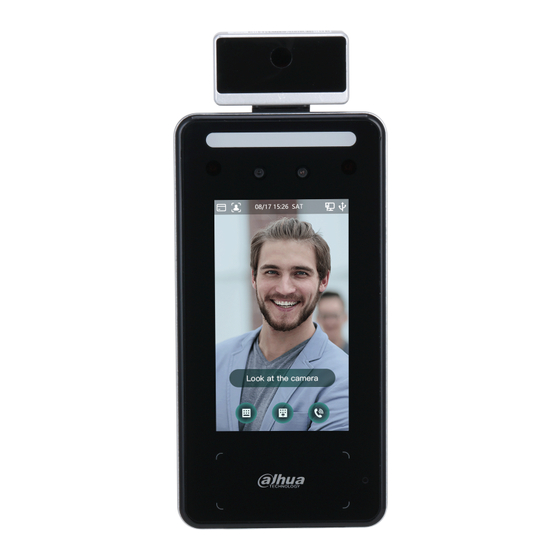
Initialization Administrator password and an email should be set the first time the access controller is turned on or after reset; otherwise the access controller cannot be used. Initialization Administrator and password set on this interface are used to log in to the web ... - Page 12 Standby interface of model J Standby interface of model G Table 2-2 Homepage description No. Description Unlock methods: Card, face, fingerprint and password. When card, face, fingerprint and password are all set as unlock mode, the password icon will not be displayed at the top left corner of the access controller. Date &...
-
Page 13: Main Menu
No. Description Display the network status and USB status. Face recognition area. Password unlock icon. Administrator password unlock icon. Tap to call other devices. Card swiping area. Main Menu Administrators can add users of different levels, set access-related parameters, do network configuration, view access records and system information, and more in the main menu. -
Page 14: Unlocking Methods
Main menu Unlocking Methods You can unlock the door through faces, passwords, fingerprint and cards. 2.6.1 Cards Put the card at the card swiping area to unlock the door. 2.6.2 Face Make sure that your face is centered on the face recognition frame, and then you can unlock the door. -
Page 15: User Password
2.6.4 User Password Enter the user password, and then you can unlock the door. on the homepage. Tap PWD Unlock. Enter the user ID and password, and then tap The door is unlocked. 2.6.5 Administrator Password Enter the administrator password, and then you can unlock the door. There is only one administrator password for one access controller. - Page 16 New User Info Configure parameters on the interface. Table 2-3 New user parameter description Parameter Description Enter user IDs. The IDs can be numbers, letters, and their combinations, and the User ID maximum length of the ID is 32 characters. Each ID is unique. Name Enter names with at most 32 characters (including numbers, symbols, and letters).
-
Page 17: Viewing User Information
Parameter Description You can select a user level for new users. There are two options: User: Users only have door unlock permission. Admin: Administrators can unlock the door and also have parameter configuration permission. User Level No matter whether there is an administrator in the access controller, administrator identity authentication is needed. -
Page 18: Period Management
2.8.1 Period Management You can set periods, holiday periods, holiday plan periods, door normally on periods, door normally closed periods, and remote verification periods. 2.8.1.1 Period Config For model G access controllers, you can configure periods locally; for model J access controllers, you can configure periods through web interface. -
Page 19: Unlock
2.8.1.5 NC Period If a period is added to the NC period, then the door is normally closed in that period. Users can not unlock the door in this period. 2.8.1.6 Remote Verification Period If you configured the remote verification period, then when unlock doors during the period you configured, remote verification is required. - Page 20 Element (multiple choice) Select one or more unlock methods. The unlock methods displayed in the figure above are for reference only, and might vary with different models. Tap a selected unlock method again to deselect it. Select a combination mode. + And: For example, if you select card + PWD, you need to swipe your card first, ...
-
Page 21: Alarm Configuration
2.8.3 Alarm Configuration Administrators can manage visitors’ unlock permission through alarm configuration. Log in to the Main Menu interface. Select Access > Alarm. Alarm means enabled. means disabled. Table 2-4 Parameters on the alarm interface Parameter Description After the anti-passback is enabled, users need to verify identities both for entry and exit;... -
Page 22: Door Status
2.8.4 Door Status There are three options: NO, NC, and Normal. NO: If NO is selected, the door status is normally open, which means the door will never be closed. NC: If NC is selected, the door status is normally closed, which means the door will not be ... -
Page 23: Network Communication
Attendance status For the six statuses, you can define them as needed, such as Check In for the start of a work day and Break Out for the start of lunch break. Network Communication To make the access controller work normally, you need to configure parameters for network, serial ports and Wiegand ports. -
Page 24: Active Register
IP address configuration Table 2-5 IP configuration parameters Parameter Description The IP address, subnet mask, and gateway IP address should be on the IP Address/Subnet Mask/Gateway IP same network segment. After configuration, tap to save the Address configurations. DHCP (Dynamic Host Configuration Protocol). When the DHCP is enabled, the IP address can be automatically acquired, DHCP and the IP address, subnet mask and gateway IP address cannot be... -
Page 25: Wi-Fi
Name Parameter Server IP Address IP address of the managing platform. Port Port number of the managing platform. Device ID Subordinate device number on the managing platform. 2.10.3 Wi-Fi You can connect the access controller to the network through Wi-Fi if the access controller has Wi-Fi function. -
Page 26: Wiegand Configuration
Select Serial Input when external devices that are with card reading and writing functions are connected to the access controller. Serial Input is selected to enable access card information to be sent to the access controller and the management platform. For access controllers with face recognition, card reading and writing functions, if you ... -
Page 27: System
System 2.11.1 Time You can do date format setting, date setting, time setting, DST setting, NTP check, and time zone settings. Log in to the Main Menu interface. Select System > Time, and then configure time parameters. Time When you select Network Time Protocol (NTP), you need to enable the NTP Check ... - Page 28 Face parameter Tap a parameter and do configuration, and then tap Table 2-8 Face parameters Parameter Description Face recognition accuracy can be adjusted. The larger the value is, the Face Threshold higher the accuracy will be. Set the control panel shooting angle of profiles. The larger the value is, Max.
- Page 29 Parameter Description Temp Correction Duration (ms): When monitoring temperature, the access controller will take the temperature value after the time defined by this parameter. Only certain models support this parameter. : Set the temperature threshold. The High Temp Threshold monitored body temperature will be judged as high temperature if it is greater than or equal to the set value.
-
Page 30: Image Mode
Parameter Description Average: Take the average temperature as the result. Only the access controller with a temperature monitoring unit supports this parameter. : Mask is not detected during face recognition. No detect : Mask is detected during face recognition. If the Mask reminder person is detected without wearing a mask, the system will prompt mask reminder and passage is allowed. -
Page 31: Screen Settings
2.11.7 Screen Settings You can set the screen saver time and screen off time. Log in to the Main Menu interface. Select System > Screen Settings. Screen settings 2.11.8 Restore to Factory Settings Data will be lost if you restore the access controller to the factory settings. ... -
Page 32: Usb Export
USB can also be used to update the program. 2.12.1 USB Export You can export data from the access controller to the USB after inserting the USB. The data exported is encrypted and cannot be edited. Log in to the Main Menu interface. Select USB >... -
Page 33: Usb Update
USB Import Select the data type that you want to import. Tap OK. Data in the USB flash drive will be imported into the access controller. 2.12.3 USB Update USB flash drive can be used to update the system. Rename the updating file name to "update.bin", and save the "update.bin" file in the root directory of the USB flash drive. - Page 34 Features Table 2-9 Feature description Parameter Description Privacy Setting See "2.13.1 Privacy Setting" for details. If the third-party card reader needs to be connected to the access controller through the wiegand output port, you need to enable the card Card No. Reverse number reverse function;...
-
Page 35: Privacy Setting
2.13.1 Privacy Setting Privacy setting Table 2-10 Privacy setting Parameter Description PWD Reset If the PWD Reset Enable function is enabled, you can reset the password. Enable The PWD Reset function is enabled by default. Hypertext Transfer Protocol Secure (HTTPS) is a protocol for secure communication over a computer network. -
Page 36: Result Feedback
Parameter Description Enable this mode to display the temperature of the blackbody on the standby interface. You can correct the temperature of the blackbody accordingly. Debug Mode Only certain models support this function. When this mode is enabled, the door cannot be opened by any method. ... - Page 37 Photo&Name Mode The image saved in the face database, user ID, user name and time are all displayed during unlock. Photo and name mode (2) Only Name Mode Only user ID, user name and time are displayed during unlock.
- Page 38 Only name mode Success/Failure Mode Only display success or failure during unlock. Success/Failure mode...
-
Page 39: Record
Record You can query all unlocking records. Search punch records System Info You can view data capacity, device version, and firmware information of the access controller on the System Info interface. Log in to the Main Menu interface. Tap System Info. System info... -
Page 40: Web Operations
Web Operations The access controller can be configured and operated on the web. Through the web you can set network parameters, video parameters, and access controller parameters; and you can also maintain and update the system. Initialization You need to set a password and an email address before logging in to the web for the first time. Open IE web browser, and enter the IP address (the default address is 192.168.1.108) of the access controller in the address bar, and then press Enter. - Page 41 Click Next. Auto check You can decide whether to select Auto Check or not. It is recommended that Auto Check be selected to get the latest program in time. Click Next. Finished configuration Click Complete, and the initialization is completed.
-
Page 42: Login
Login Open IE web browser, enter the IP address of the access controller in the address bar, and press Enter. Use browser newer than IE 8, otherwise you might not log in to the web. Make sure that the computer used to log in to the web is in the same LAN with the ... - Page 43 Tips Read the tips. Click OK. Reset Password Scan the QR code on the interface, and you will get the security code. At most two security codes will be generated by scanning the same QR code. If security codes become invalid, to get more security codes, refresh the QR code. You need to send the content you get after you scanned the QR code to the ...
-
Page 44: Door Parameter
Please use the security code within 24 hours after you receive it. Otherwise, it will become invalid. If wrong security codes are entered for consecutive five times, the administrator will be frozen for five minutes. Enter the security code you have received. Click Next. - Page 45 2) Configure the time and opening method for a time section. You can configure up to four time sections for each day. 3) (Optional) Select Apply to the whole week to copy the configuration to other days. 4) Click OK Multi-person ...
-
Page 46: Alarm Linkage
Table 3-1 Parameter description Parameter Description Name Enter a name for the door that this access controller controls. Select NC for normally closed, or NO for normally open. If either is selected, State the defined opening method will not be effective. Opening See Step 3 above. -
Page 47: Alarm Log
Change alarm linkage parameters Table 3-2 Alarm linkage parameter description Parameter Description Alarm Input You cannot modify the value. Keep it default. Name Enter a zone name. If alarm input type of the alarm device you purchased is NO, then you Alarm Input Type should select NO;... -
Page 48: Talkback Setting
Alarm log Select a time range and alarm type, and then click Query. The query results are displayed. Query results Talkback Setting The access controller can work as a door station (VTO) and call other devices. 3.6.1 SIP Server On the web, you can add door stations and indoor stations to the SIP server so that they can talk to each other. - Page 49 Select Talkback Setting > SIP Server. Enable SIP Server, and then click OK. The access controller will restart. SIP server (1) 3.6.1.2 Other Device as SIP Server Log in to the web interface. Select Talkback Setting > SIP Server. Disable SIP Serve, and then set Server Type to VTO. Configure the parameters...
-
Page 50: Local Configuration
SIP server (2) Table 3-3 SIP server parameter description (1) Parameter Description IP Address The IP address of the VTO working as the SIP server. Port 5060 by default. Username Keep the default values. Password Must be VDP. Domain SIP Server Username SIP server login username and password. - Page 51 Configure the parameters. Local (1) Table 3-4 Parameter description Parameter Description Device Type The access controller can only work as a unit VTO. Centre Call Enter a number for the management center. It can contain up tp nine digits. Cannot be configured when the access controller is working as the SIP VTO No.
-
Page 52: Vto Number Management
Parameter Description Set a number. It should be four digits. The first two should be 80 and the VTO No. last two starts with 01, such as 8001. If there are multiple VTOs, their VTO numbers cannot be the ... -
Page 53: Vth Number Management
Add a door station Table 3-6 Parameter description Parameter Description Rec No. Enter a number for the VTO you want to add. Register Password Keep it default. Build No. Cannot be configured. Unit No. IP Address IP address of the VTO you want to add. Username Web interface login username and password of the VTO you want to Password... - Page 54 Room number management Enter the information. Add one VTH Table 3-7 Parameter description Parameter Description First Name Last Name To differentiate from othe rVTHs. Nick Name Room number of the VTH. It can contain up to five digits and must be the same as the one ...
-
Page 55: Vts Management
Parameter Description Register Type Keep it default. Register Password Click OK. You can click Export to export the room number and import them to other devices. 3.6.4.2 Add VTHs in Batches You can add up to 1024 VTHs. Log in to the web interface. Select Talkback Setting >... -
Page 56: Online Status
Add managing devices Enter the information. VTS No.: It can contain up to nine digits. Register Password: Keep it default. IP Address: IP address of the VTS. Click OK. Related Operations : Modify the information of a VTS. ... -
Page 57: Call Logs
Status 3.6.7 Call Logs You can check up to 1024 call logs. Log in to the web interface. Select Talkback Setting > Call. (Optional) Click Export Data to export all the logs. Call logs... -
Page 58: Time Section
Time Section Configure time sections and holiday plans, and then you can define when a user has the permissions to unlock doors. 3.7.1 Configuring Time Section Set when a user can unlock doors each day. Log in to the web interface. Select Time Section >... -
Page 59: Configuring Holiday Group
Add a holiday group Enter a number and a name for the holiday group. Click Add. Add a holiday Enter a name for the holiday, select the start and end date, and then click OK. You can add multiple holidays for one holiday group. Click OK. -
Page 60: Data Capacity
Add a holiday plan Enter a number and name for the holiday plan. Select the number of a holiday group you configured. Select 255 if you do not want to select a holiday group. Configure periods for every day in the holiday group you selected. You can configure up to four periods. -
Page 61: Image
Data rate Table 3-8 stream parameter description Parameter Description Select NTSC or PAL according to the video standard of your Video Standard region. There are two options: 1 and 2. 1 is white light camera and 2 is IR Channel light camera. - Page 62 Image Select Wide Dynamic in the Backlight Mode. Table 3-9 Image parameter description Parameter Description Brightness The larger the value is, the brighter the images will be. Contrast is the difference in luminance or color that makes an object Contrast distinguishable.
-
Page 63: Exposure
Parameter Description Close: Without backlight compensation. BLC: Backlight compensation corrects regions with extremely high or low levels of light to maintain a normal and usable level of light for the object in focus. WDR: In the wide dynamic range mode, the system dims bright areas and compensates dark areas to ensure the definition of objects in the bright areas and dark areas. -
Page 64: Motion Detection
Parameter Description Auto: The access controller will automatically adjust brightness of images. Shutter Priority: The access controller will adjust image brightness according to shutter exposure value range. If the image brightness is not enough and the shutter value has reached upper or lower limit, the access controller will adjust gain value automatically to get ideal brightness. - Page 65 Motion detection Press and hold the left mouse button, and then drag the mouse in the red area. The red rectangles are motion detection area. The default motion detection range is all the rectangles. To draw a motion detection area, you need to click Remove All first. ...
-
Page 66: Volume Setting
Sensitivity represents the ability of each grid to sense motion. The larger the value is, the higher the sensitivity is. Threshold is the condition of motion detection. When grid number reaches the threshold, motion detection will be triggered. The smaller the value is, the more likely the motion detection will be triggered. -
Page 67: Local Coding
3.9.7 Local Coding Set up the area to be displayed on the indoor monitors. Log in to the web. Select Video Setting > Local Coding. Enable the function. Local coding Click OK. Face Detection You can configure human face related parameters on this interface to increase face recognition accuracy. - Page 68 Face detect Configure parameters. Table 3-11 Face detect parameter description Parameter Description Face Recognition The larger the value is, the higher the accuracy will be. Threshold Max. Angle of Face The larger the angle is, the wider range of the profiles will be Recognition recognized.
- Page 69 Parameter Description Pupillary distance is the pixel value of the image between the centers of the pupils in each eye. You need to set an appropriate value so that the access controller can recognize faces as needed. Pupillary Distance The value changes according to the face sizes and the distance between faces and the lens.
-
Page 70: Network Setting
Parameter Description Auto: Uses a face heat map for face recognition; if heat maps are not found, it will automatically change to calibration mode. Thermogram: Uses only a heat map for face recognition and temperature monitoring. Temp Monitoring Calibration: Uses a white light image of a face for face Mode recognition, and then extract and apply the coordinates on the face heat map for temperature monitoring. - Page 71 TCP/IP Configure parameters. Table 3-12 TCP/IP Parameter Description IP Version There is one option: IPv4. MAC Address MAC address of the access controller. Static: Set IP address, subnet mask, and gateway address manually. DHCP After DHCP is enabled, IP address, subnet mask, and gateway ...
-
Page 72: Port
3.11.2 Port Set the maximum connections clients that the access controller can be connected to and port numbers. Log in to the web interface. Select Network Setting > Port. Configure port numbers. See the following table. Except max connection, you need to reboot the access controller to make the configuration effective after modifying values. -
Page 73: Register
Table 3-13 Port description Parameter Description You can set the maximum connections of clients that the access controller can be connected to. Connection Platform clients like SmartPSS AC are not counted. TCP Port Default value is 37777. Default value is 80. If other value is used as port number, you need to add this HTTP Port value behind the address when logging in through browsers. -
Page 74: Safety Management
Log in to the web interface. Select Network Setting > P2P. Select Enable to enable the P2P function. Click OK. Scan the QR code on your web interface to get the serial number of the access controller. Safety Management 3.12.1 IP Authority Select a cybersecurity mode as needed. -
Page 75: Systems
3.12.2 Systems 3.12.2.1 System Service Enable or disable the system services as needed. The system service configuration on the web interface is synchronized to the Features interface of the access controller. System service Table 3-15 Parameter description Parameter Description Secure Shell (SSH) is a cryptographic network protocol for operating network services securely over an unsecured network. -
Page 76: User Management
Parameter Description Common Gateway Interface (CGI) offers a standard protocol for web servers to execute programs similarly to console applications running on a server that dynamically generates web pages. When CGI is enabled, CGI commands can be used. The CGI is enabled by default. -
Page 77: Adding Users
3.13.1 Adding Users Click Add on the User Mgmt. interface to add users, and then enter username, password, confirmed password, and remark. Click OK to complete the user adding. 3.13.2 Modifying User Information You can modify user information by clicking on the User Mgmt. -
Page 78: Maintenance
Maintenance You can make the access controller reboot itself in idle time to improve the running speed of the access controller. You need to set the auto reboot date and time. Log in to the web interface. Select Maintenance. Set the auto reboot time, and then click OK. Maintenance For example, the access controller will reboot at 2 O’clock in the morning every Tuesday. -
Page 79: Importing Configuration File
3.15.2 Importing Configuration File You can import the configuration file that is exported from an access controller to another access controller with the same model. Log in to the web interface. Select Config Mgmt. on the navigation bar. On the configuration management interface, click Browse to select the configuration file that you want to import, and then click Import configuration. -
Page 80: Version Information
You can select Auto Check to upgrade the system automatically. You can also select Manual Check to upgrade the system manually. The access controller will reboot after upgrade. You click Version Info on the left navigation menu to check version after ... -
Page 81: Admin Log
Log in to the web interface. Select System Log > System Log. Select a time range and a type, and then click Query. Click Backup to download the results. Seach for logs 3.19.2 Admin Log Search for admin logs by admin ID. Log in to the web interface. -
Page 82: Fusion Calibration
Click Export Data to download the results. Fusion Calibration Set up the coordinate relationship between the white light face image and face heat map. When calibration mode is enabled, the access controller will use the coordinate relationship to measure temperature on the face heat map. Only certain models support this function. -
Page 83: Advanced
Advanced You can view environment temperature, and core temperature and body surface temperature of a target. Only certain models support this function. Exit Click at the upper-left corner, and then click OK to log out of the web interface. -
Page 84: Smartpss Ac Configuration
SmartPSS AC Configuration You can manage the access controller through the SmartPSS AC client. For detailed configurations, see the SmartPSS AC user manual. SmartPSS AC interfaces might vary with versions, and the actual interface shall prevail. Login Install the SmartPSS AC. Double-click , and then follow the instructions to finish the initialization and log Adding Devices... -
Page 85: Manual Add
Auto search Enter the network segment, and then click Search. A search result list will be displayed. Select access controllers that you want to add to the SmartPSS AC, and then click Add. The Login information dialog box will be displayed. Enter the username and the login password to login. -
Page 86: User Management
Manual add Enter the device name, select a method to add, enter the IP, Port number (37777 by default), User Name, and Password. Click Add, and then you can see the added access controller on the Devices interface. User Management 4.3.1 Card Type Setting Before issuing card, set card type first. -
Page 87: Adding User
Personnel manager On the Personnel Manager interface, click , then click On the Setting Card Type interface, select a card type. Click to select display method of card number in decimal or in hex. Setting card type Click OK. 4.3.2 Adding User Select one of the methods to add user. - Page 88 Make sure that the image pixels are more than 500 × 500; image size is less than 120 KB. Add basic information Click the Certification tab to add certification information of the user. Configure password. ...
- Page 89 Set password. For the second generation access controllers, set the personnel password; for other devices, set the card password. The new password must consist of 6 digits. Configure card. The card number can be read automatically or filled in manually. For automatically read, select a card reader, and then place the card on the card reader.
- Page 90 Configure certification Configure permission for the user. For details, see "4.4 Permission Configuration".
- Page 91 Permission configuration Click Finish. 4.3.2.2 Batch Add You can add users in batches. Log in to SmartPSS AC. Click Personnel Manger > User > Batch Add. Select card reader and the department of user. Set the start number, card quantity, effective time and expired time of card.
- Page 92 Add user in batches In the list of user, click to modify information or add details of users. 4.3.2.3 Extracting User from Devices You can extract user information from devices. Log in to SmartPSS AC. Click Personnel Manger > User > Extract. Search and select the target device, and then click OK.
-
Page 93: Issuing Card In Batches
Devices with user information Select users as needed, and click Extract. In the list of user, click to modify information or add details of user. 4.3.2.4 Importing User You can import users locally. Log in to SmartPSS AC. Click Personnel Manger > User > Import. Import user information according to instructions. -
Page 94: Exporting User Information
Issue card in batches Click OK. 4.3.4 Exporting User Information You can export user information. Log in to SmartPSS AC. Select Personnel Manager > User. Select the user information which needs to be exported, and then click Export to export all user information to local. Permission Configuration 4.4.1 Adding Permission Group Log in to SmartPSS AC. - Page 95 Click Personnel Manger > Permission Configuration. Permission group list Click to add a permission group. Set permission parameters. Enter group name and remark. Select the needed time template. For details of time template setting, see SmartPSS AC user manual. Select the corresponding device, such as door 1. Add permission group Click OK.
-
Page 96: Configuring Permission
On the Permission Group List interface, you can do: Click to delete group. Click to modify group info. Double-click permission group name to view group info. 4.4.2 Configuring Permission The method to configure permission for department and for users is similar. This section takes users as an example. -
Page 97: Access Management
Access Management 4.5.1 Remotely Opening and Closing Door After access configuration, you can remotely control door through SmartPSS AC. Click Access Manager on the homepage. (Or click Access Guide > Remotely control the door. There are two methods. Method 1: Select the door, right click and select Open. ... -
Page 98: Setting Always Open And Always Close
4.5.2 Setting Always Open and Always Close After setting always open or always close, the door is open or closed all the time and cannot be controlled manually. If you want to manually control the door again, click Normal to reset the door status. -
Page 99: Attendance Management
Attendance Management You can set attendance time, add attendance shifts, personnel scheduling, process attendance, manage attendance statistics, search reports, add holidays, and configure attendance. 4.6.1 Report Search You can view the normal attendance, attendance abnormality, overtime attendance and staff information here. And the statistics can be exported as reports. Log in to SmartPSS AC. -
Page 100: Other Configurations
4.6.2 Other Configurations For other configurations such as attendance periods, attendance shifts, personnel scheduling, attendance processing and attendance statistics, adding holidays and attendance configurations, refer to the SmartPSS AC user's manual. Log in to SmartPSS AC. Click on the left menu. Click Attendance Guide at the lower-right corner. -
Page 101: Faq
The access controller fails to start after power-on. Check whether the 12V power supply is correctly connected, and whether the power button is pressed. Faces cannot be recognized after the access controller powers on. Make sure that Face is selected in the unlock mode. See “2.8.2 Unlock”. There is no output signal when the access controller and the external controller are connected to the Wiegand port. -
Page 102: Notes Of Face Recording/Comparison
Notes of Face Recording/Comparison Before Registration Glasses, hats, and beards might influence face recognition performance. Do not cover your eyebrows when wearing hats. Do not change your beard style greatly if you will use the device; otherwise face ... - Page 103 Do not shake your head or body, otherwise the registration might fail. Avoid two faces appear in the capture frame at the same time. Face Position If your face is not at the appropriate position, face recognition effect might be influenced. Appendix Figure 1-2 Appropriate face position Requirements of Faces Make sure that the face is clean and forehead is not covered by hair.
- Page 104 Appendix Figure 1-3 Head position Appendix Figure 1-4 Face distance When importing face images through the management platform, make sure that image resolution is within 150 × 300 to 600 × 1200; image pixels are more than 500 × 500; image size is less than 75 KB, and image name and person ID are the same.
-
Page 105: Cybersecurity Recommendations
Cybersecurity Recommendations Cybersecurity is more than just a buzzword: it’s something that pertains to every device that is connected to the internet. IP video surveillance is not immune to cyber risks, but taking basic steps toward protecting and strengthening networks and networked appliances will make them less susceptible to attacks. - Page 106 We suggest you to change default HTTP and other service ports into any set of numbers between 1024~65535, reducing the risk of outsiders being able to guess which ports you are using. Enable HTTPS We suggest you to enable HTTPS, so that you visit Web service through a secure communication channel.
- Page 107 Enable IP/MAC address filtering function to limit the range of hosts allowed to access the device.
Need help?
Do you have a question about the ASI6213J-FT and is the answer not in the manual?
Questions and answers