Sign In
Upload
Download
Add to my manuals
Delete from my manuals
Share
URL of this page:
HTML Link:
Bookmark this page
Add
Manual will be automatically added to "My Manuals"
Print this page
×
Bookmark added
×
Added to my manuals
Manuals
Brands
Dahua Manuals
IP Access Controllers
ASA4214F
User manual
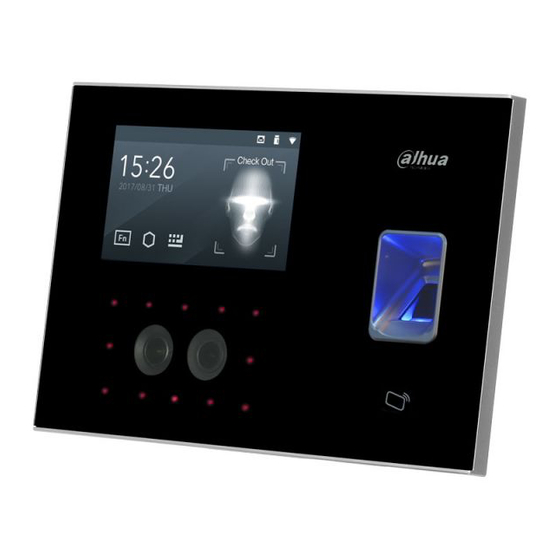
Dahua ASA4214F User Manual
Face recognition access and time attendance terminal
Hide thumbs
1
2
3
4
5
6
7
Table Of Contents
8
9
10
11
12
13
14
15
16
17
18
19
20
21
22
23
24
25
26
27
28
29
30
31
32
33
34
35
36
37
38
39
40
41
42
43
44
45
46
47
48
49
50
51
52
53
54
55
56
57
58
59
60
61
62
63
64
65
66
67
68
69
page
of
69
Go
/
69
Contents
Table of Contents
Bookmarks
Advertisement
Quick Links
1
Super Password
2
Restore Factory
3
Network Configuration
4
Forget Admin and Fail to Set
Download this manual
Face Recognition Access and Time
Attendance Terminal
User's Manual
V1.0.0
Table of
Contents
Previous
Page
Next
Page
1
2
3
4
5
Advertisement
Need help?
Do you have a question about the ASA4214F and is the answer not in the manual?
Ask a question
Questions and answers
Related Manuals for Dahua ASA4214F
IP Access Controllers Dahua ASA1222E User Manual
Time attendance (standalone) (44 pages)
IP Access Controllers Dahua ASA2212A User Manual
Standalone time attendance (48 pages)
IP Access Controllers Dahua ASA6214F User Manual
Face recognition access and time attendance terminal (69 pages)
IP Access Controllers Dahua ASA3223A-W User Manual
Face recognition time & attendance (102 pages)
IP Access Controllers Dahua ASR1102A User Manual
Fingerprint access control card reader (10 pages)
IP Access Controllers Dahua ASC1204B-S User Manual
Four-door access controller (16 pages)
IP Access Controllers Dahua ASI7223X-A User Manual
Face recognition terminal (77 pages)
IP Access Controllers Dahua ASC2102B-T User Manual
Two door two-way slave access controller (19 pages)
IP Access Controllers Dahua ASC2102B-T User Manual
Two-door sub access controller (20 pages)
IP Access Controllers Dahua ASC1208C-S User Manual
(15 pages)
IP Access Controllers Dahua ASI6213J-FT User Manual
Face recognition access controller (107 pages)
IP Access Controllers Dahua ASI7223X-A-T1 Quick Start Manual
Face recognition terminal (19 pages)
IP Access Controllers Dahua ASC1204B User Manual
Four-door one-way access controller (36 pages)
IP Access Controllers Dahua ASI7214X User Manual
Face recognition access controller (93 pages)
IP Access Controllers Dahua ASC3202B Quick Start Manual
(67 pages)
IP Access Controllers Dahua ASR2101H-D User Manual
Access reader (17 pages)
This manual is also suitable for:
Asa6214f
Print
Rename the bookmark
Delete bookmark?
Delete from my manuals?
Login
Sign In
OR
Sign in with Facebook
Sign in with Google
Upload manual
Upload from disk
Upload from URL


Need help?
Do you have a question about the ASA4214F and is the answer not in the manual?
Questions and answers