Table of Contents
Advertisement
Quick Links
Advertisement
Table of Contents

Related Manuals for Dahua ASC2102B-T


Summary of Contents for Dahua ASC2102B-T
- Page 1 Two door two-way Slave Access Controller User’s Manual V1.0.0...
-
Page 2: Legal Statement
Legal Statement Trademark VGA is the trademark of IBM. Windows logo and Windows are trademarks or registered trademarks of Microsoft. Other trademarks and company names mentioned are the properties of their respective owners. About this Document This document is for reference only. Please refer to the actual product for more details. ... -
Page 3: Preface
Preface Overview This document elaborates on structure, installation, interface and wiring of two-door slave access controller. Symbol Definition The following symbols may appear in this document. And their meanings are as follows: Symbol Note It indicates a potentially hazardous situation which, if not avoided, could result in death or serious injury. -
Page 4: Important Safeguards And Warnings
Important Safeguards and Warnings The following description is the correct application method of the device. Please read the manual carefully before use, in order to prevent danger and property loss. Strictly conform to the manual during application and keep it properly after reading. Operating Requirement Please don’t place and install the device in an area exposed to direct sunlight or near heat ... -
Page 5: Table Of Contents
Table of Contents Legal Statement ............................I Preface ............................... II Important Safeguards and Warnings ....................III 1 Overview .............................. 1 2 Packing List ............................2 3 Installation Guide ..........................3 3.1 System Structure........................... 3 3.2 External Dimension ........................3 3.3 Device Installation ......................... 4 3.4 Disassembly .......................... -
Page 6: Overview
Overview As a slave controller of access master controller, two-door slave access controller is matched with access master controller and is widely used in banks, prisons and safe places. Its rich functions are as follows: Adopt sliding rail type and lock type installation, convenient installation and maintenance. ... -
Page 7: Packing List
Packing List Before installation, please check according to Table 2-1. Name Quantity Access controller Installation positioning drawing Accessory kit (screw, expansion pipe and wiring terminal) Quick start guide Certificate of qualification Table 2-1... -
Page 8: Installation Guide
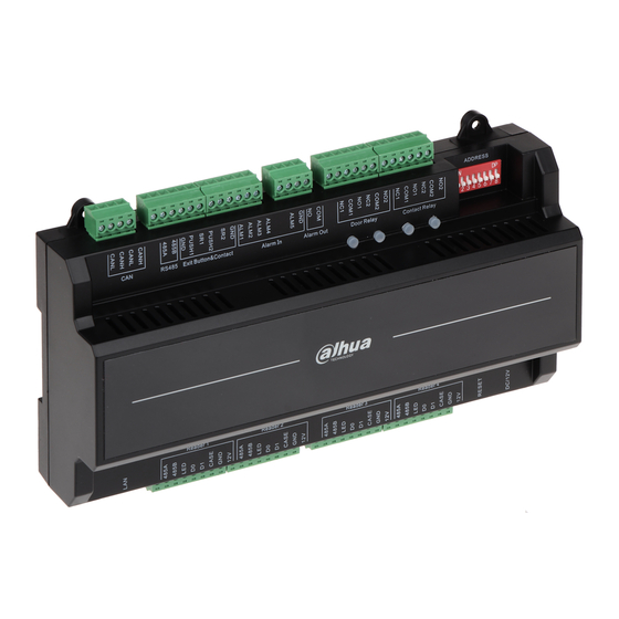
Installation Guide System Structure System structure of two-door slave access controller, door lock and reader is shown in Figure 3-1. Figure 3-1 External Dimension Its appearance and dimension is shown in Figure 3-2 and Figure 3-3. The unit is mm. -
Page 9: Device Installation
Figure 3-2 Figure 3-3 Device Installation There are two installation modes. Mode 1: fix the whole device onto the wall with screws. Mode 2: install U-shaped guide rail, and hang the whole device onto the wall (U-shaped guide rail is a self-bought fitting). Mode 1 Installation diagram is shown in Figure 3-4. -
Page 10: Disassembly
Figure 3-4 Mode 2 Installation diagram is shown in Figure 3-5. Figure 3-5 Step 1 Fix the U-shaped guide rail onto the wall with screws. Step 2 Buckle the upper rear part of the device into upper groove of U-shaped guide rail. Step 3 Push the snap joint at the bottom of the device upwards. -
Page 11: Wiring Description
whole device can be disassembled smoothly. Figure 3-6 Wiring Description Device wiring diagram is shown in Figure 3-7. Figure 3-7 Interfaces are described in Table 3-1. -
Page 12: Wiring Description Of Can Bus
Interface Description Interface Description CAN bus Not available at present External extension module Entry reader of door 1 Door sensor and exit button Exit reader of door 1 External alarm input Entry reader of door 2 External alarm output Exit reader of door 2 Lock control output Reboot Internal alarm output... -
Page 13: Wiring Description Of External Alarm Input
Interface Wiring Terminal Description sensor sensor input of door 1 PUSH1 Exit button of door 1 Door sensor input of door 1 PUSH2 Exit button of door 2 Door sensor input of door 2 Shared by exit button of door 2 and door sensor input of door 2 Table 3-4 3.5.3 Wiring Description of External Alarm Input... -
Page 14: Wiring Description Of Lock
Figure 3-10 Figure 3-11 Interface Wiring Terminal Description External alarm External alarm output interfaces are able output to connect audible and visual sirens. Table 3-6 3.5.5 Wiring Description of Lock Support 2 groups of lock control outputs; serial numbers after the terminals represent corresponding doors. -
Page 15: Wiring Description Of Internal Alarm Output
Figure 3-14 Interface Wiring Terminal Description COM1 Lock control of door 1 Lock control output COM2 Lock control of door 2 Table 3-7 3.5.6 Wiring Description of Internal Alarm Output Corresponding wiring terminals of internal alarm control output are shown in Table 3-8. Interface Wiring Terminal Description... -
Page 16: Dip Switch
Interface Wiring Terminal Cable Color Description Table 3-9 Reader Type Connection Mode Length 485 Reader CAT5e network cable, 485 connection 100m Wiegand Reader CAT5e network cable, Wiegand connection Table 3-10 DIP Switch Set device number and speed with DIP switch. DIP switch is shown in Figure 3-15. Please refer Function No. - Page 17 Table 3-11 for details. the switch is at ON position, meaning 1. the switch is at the bottom, meaning 0. Figure 3-15 Function Description Set device number with binary system. The left is the lowest order. For example: Device 1~5 Number...
-
Page 18: Reboot
Reboot Insert a needle into RESET hole, and long press the reboot controller. -
Page 19: Technical Parameters
Technical Parameters Parameter Specification Processor 32-bit ARM processor Storage Capacity Max User 20,000 Max Record 30,000 Communication Port of Reader Wiegand,RS485 Communication Port Quantity of Connected Reader 4 groups Working Power Rated power 10V~15V DC, rated current 0.75A Real-time Monitoring Support Fire Alarm Linkage Support...
Need help?
Do you have a question about the ASC2102B-T and is the answer not in the manual?
Questions and answers