Table of Contents
Advertisement
Quick Links
Advertisement
Table of Contents

Related Manuals for Dahua ASI1212AD


Summary of Contents for Dahua ASI1212AD
- Page 1 Fingerprint Access Control Integration Host User’s Manual V1.1.3...
-
Page 2: Table Of Contents
Table of Contents Overview...................... 0 Device Structure and Installation ..............1 System Structure ..................3 System Structure..................... 3 Device Port ..................... 3 Function Setting ................... 6 Login ....................... 6 User Management ................... 6 4.2.1 Add User ....................7 4.2.2 Add Super Password ................8 4.2.3 Delete User ................... - Page 3 4.5.3 Local Info .................... 19...
- Page 4 Important Safeguards and Warnings Please read the following safeguards and warnings carefully before using the product in order to avoid damages losses and body injuries. After reading, please well keep this user's manual. Note: Please change user default password after being armed. ...
- Page 5 identification to inform data subject the existence of surveillance area and providing related contact. About the Manual The Manual is for reference only. If there is inconsistency between the Manual and the actual product, the actual product shall prevail. We are not liable for any loss caused by the operations that do not comply ...
-
Page 6: Overview
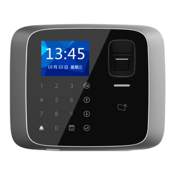
1 Overview The Fingerprint Access Control Integration Host integrates card reading, config and execution functions. Its has a neat appearance for medium to high-end clients such as commercial building, corporation and intelligent community. It has: Touch keyboard + LCD display, TCP/IP protocol. ... -
Page 7: Device Structure And Installation
2 Device Structure and Installation Device appearance and dimension are shown as in Figure 2- 1 and Figure 2- 2. Unit is mm. Figure 2- 1 Figure 2- 2... - Page 8 Fingerprint Access Control Integration Host installation is shown as in Figure 2- 3. Figure 2- 3 Installation step: Step 1. Fix installation bracket in the hole on 86 box via screw A as to fix the bracket on wall (if no 86 box or you cannot fix it well, then use screw B to fix the bracket on wall, but you must embed expansion nut at the corresponding position in wall before doing so).
-
Page 9: System Structure
3 System Structure 3.1 System Structure The device and card reader, alarm device, access control PC and etc. compose a system as in Figure 3- 1. Figure 3- 1 3.2 Device Port Device port of the host is shown in Figure 3- 3. - Page 10 Figure 3- 2 Figure 3- 3 Port Note Door lock COM end Door lock NC end Door lock NO end Door sensor detection Connect to GND PUSH Press unlock button BELL- Door bell output BELL+ Alarm output 2 ( 5V level switch) , connect OUT2-...
- Page 11 Port Note OUT2+ to voltage not over 12V Alarm output 1 ( 5V level switch) , connect OUT1- to voltage not over 12V OUT1+ 485+ RS485+, 485 card reader 485- RS485-, 485 card reader LED_OUT, Weigand card reader D0, Weigand card reader D1, Weigand card reader CASE Card reader protection alarm...
-
Page 12: Function Setting
4 Function Setting 4.1 Login Login interface step: Step 1. Plug in power, device is going to boot up. Step 2. Press 【√】 button, screen displays admin password. Step 3. Input admin password, and press 【√】 button to enter homepage. Default password is “88888888”. -
Page 13: Add User
Card Type Note Black list When you swipe card on black list and enters, it wanrns service personal. When you add card, system will ask if set card password, period and term of validity. Duress card Duress card becomes valid after you set duress alarm. You can swipe this card to unlock, but an alarm will be send to center. -
Page 14: Add Super Password
Step 3. Use key to input card no. or place card at swiping area to scan. Step 4. Press【√】key to select card type. Step 5. Press 【←】key to delete default data, input use time, and press 【√】.System shows added password and period interface as follows. New User Card No. -
Page 15: Delete Password User
press 【√】 key. Step 2. Press【↑】or【↓】 key, to move up or down, select single card and press【√】 key. Step 3. Input no. of card to delete, place the card at swiping area, and press【√】key. Delete User User Card No. System asks if to delete it or not. Step 4. -
Page 16: Add More Master Card
4.2.5 Add More Master Card By adding more master card, user can quickly add card user. Before adding master card, user shall add master card first, please refer to Ch 4.3.2. To add more master card: Step 1. In user management interface, by pressing 【↑】 or 【↓】key to move up and down, select add more master card, and press 【√】key. - Page 17 interface. Step 3. Press 【↑】key or 【↓】key , select card swiping period, and press 【√】key. Step 4. Input time period, and press 【√】key. Input any number between 0~127. Screen displays period. Card Period Setup Mon. Tue. 00: 00 – 23: 59 Wed.
- Page 18 4.3.1.3 Mode Period Mode period has four periods per day, from Monday to Sunday, 7 days a week. To set mode period: Step 1. In time period setup interface, press 【↑】 or【↓】key, select mode period, and press【√】. System displays periods of Monday to Sunday. Mode Period Setup Mon.
-
Page 19: Master Card
4.3.2 Master Card You can modify or add master card. Step 1. In A&C setup interface, press 【↑】key or 【↓】key to select master card setup, and press 【↓】key. Step 2. Press 【←】key to delete old card no., and input modified card no., or directly place the card at swiping area for scanning, and press 【√】key, as follows. -
Page 20: Alarm
Step 2. Press【←】key to delete original data, input hold time and over time, press 【√】 key. Door Lock Time Setup Hold Time: 2000 Over Time: System prompt setup is successful. Door lock hold time is the time door remains open after user swipe card. If the door remains open exceeding “over time”, it will send alarm. -
Page 21: Door Status Setup
Alarm Setup Intrusion Anti-pass Back Duress Card Door Sensor Door Timed Out Press 【√】 key again to close the alarm. 4.3.6 Door Status Setup You can set A&C status to normal, NO or NC. Step 1. In A&C setup interface, press 【↑】key or 【↓】key, select door status setup, and press 【√】key to enter door status setup interface. - Page 22 Step 4. Input device date and device time, and press 【√】key as follows. Data Setup Device Date: 2015-03-25 Device Time: 12:36:05 System prompts setup is successful. 4.4.1.2 Admin Password Change You can modify admin password. Step 1. In local setup interface, press 【↑】 or 【↓】 key, select admin password setup, and press【√】key.
-
Page 23: Communication Setup
4.4.1.4 Default To restore default settings: Step 1. In local setup interface, press 【↑】 or 【↓】key, select default, and press【√】 key. System asks if to restore or not. Step 2. Select YES and press 【√】key to restore. 4.4.2 Communication Setup It sets current access control communication.(Only IP for now) Step 1. -
Page 24: Reboot System
Work Mode This device as controller This device as card reader ○ √ After selection is successful, a ○ √ will be shown next to work mode. 4.4.4 Reboot System To reboot the system: Step 1. In main interface, press 【↑】or【↓】key, select system reboot, and press【√】. System asks if to reboot or not. -
Page 25: Alarm History
4.5.2 Alarm History To view alarm history: Step 1. In system info interface, press 【↑】or 【↓】key, select alarm history, and press 【√】key. Step 2. Press 【↑】or 【↓】key, user can view alarm history, including alarm type, alarm time and etc as follows. Alarm History Alarm Type Alarm Time... - Page 26 information.
Need help?
Do you have a question about the ASI1212AD and is the answer not in the manual?
Questions and answers