Table of Contents
Advertisement
Advertisement
Table of Contents

Subscribe to Our Youtube Channel
Related Manuals for Dahua ASC1204B-S


Summary of Contents for Dahua ASC1204B-S
- Page 1 Four-Door Access Controller User’s Manual V1.0.2...
-
Page 2: Table Of Contents
Table of Contents 1 Overview ..........................1 2 Device Appearance ......................... 2 3 Device Installation and Uninstallation ..................3 3.1 Device Installation ....................... 3 3.2 Device Uninstallation ......................4 4 Port………………......................... 6 4.1 Port ............................6 4.2 Cabling ..........................7 4.3 System Structure ......................... - Page 3 Important Safeguards and Warnings Please read the following safeguards and warnings carefully before using the product in order to avoid damages losses and body injuries. After reading, please well keep this user's manual. Note: Please change user default password after being armed. ...
- Page 4 About the Manual The Manual is for reference only. If there is inconsistency between the Manual and the actual product, the actual product shall prevail. We are not liable for any loss caused by the operations that do not comply ...
-
Page 5: Overview
1 Overview The access controller is a controlling device which compensates video monitoring and bidirectional talk. It has neat and modern design with strong functionality, suitable for commercial building, corporation property and intelligent community. It has: It adopts slideway and lock installation design for easy installation and repair. ... -
Page 6: Device Appearance
2 Device Appearance Access controller appearance and dimension are shown in Figure 2- 1 Dimension 1 and Figure 2- 2 Dimension 2. Unit is mm. Figure 2- 1 Dimension 1 Figure 2- 2 Dimension 2... -
Page 7: Device Installation And Uninstallation
3 Device Installation and Uninstallation 3.1 Device Installation You can install the device either: Fix it on wall with screw. Fix it on wall with bracket. Installation 1: Fix device on wall with screw as in Figure 3- 1 Figure 3- 1 Installation 2: Fix it on wall with bracket as in Figure 3- 2. -
Page 8: Device Uninstallation
Figure 3- 2 Installation steps: Step 1. Fix bracket on wall with screw. Step 2. Fasten the device into slot on bracket and pull device downward until it is in place. 3.2 Device Uninstallation Uninstallation method for installation 2 is shown in Figure 3- 3. - Page 9 Figure 3- 3 Uninstallation method: Step 1. Face screwdriver toward the slot and press it to fasten. Step 2. Do it again for second slot, and you can take the device down.
-
Page 10: Port
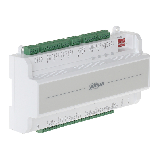
4 Port 4.1 Port Device ports are illustrated in Figure 4- 1. Figure 4- 1 Ports are defined as: Port Port RS485 communication, TCP/IP, software platform port software port No.1, 2 doors unlock No.1 door card reader +door sensor No.3, 4 doors unlock No.2 door reader +door sensor Alarm input/output... -
Page 11: Cabling
Indicators are defined as: Note Lock status indicator Power indicator 4.2 Cabling Cabling ports of No.1 to 7 are shown as Figure 4- 2. Figure 4- 2 Cabling ports of “RS485 communication” are as follows: Port Cabling Port Communication 485- 485+ Cabling ports of “Unlock+Door sensor”... - Page 12 Port Cabling Port Note PUSH3 No.3 door’s unlock button No.3 door’s unlock button and door sensor No.3 door’s door sensor PUSH4 No.4 door’s unlock button No.4 door’s unlock button and door sensor No.4 door sensor Cabling ports of “Alarm Input/Output” are as follows: Port Cabling Port Note...
-
Page 13: System Structure
Figure 4- 3 Cabling ports of “No. 1 entry card reader” are as follows. It is same for “No.1 door’s card reader”, “No.2 door’s card reader”, “No.3 door’s card reader” and “No.4 door’s card reader”. Port Cabling Port Note No.1 485+ 485 card reader Entry... - Page 14 Figure 4- 4...
-
Page 15: Technical Specification
5 Technical Specification Parameter Specification Processor 32 bit ARM processor Storage Capacity Max User 100,000 Max Record 150,000 Card Reader Wiegand, RS485 Communication Port Platform TCP/IP Communication Port Input Card Reader 4 groups Quantity Working Power Rated power 10-15VDC, rated current 0.75A Schedule Period Holiday... - Page 16 Note: This manual is for reference only. Slight difference may be found in user interface. All the designs and software here are subject to change without prior written notice. All trademarks and registered trademarks are the properties of their respective owners.
Need help?
Do you have a question about the ASC1204B-S and is the answer not in the manual?
Questions and answers