Table of Contents
Advertisement
Quick Links
Advertisement
Table of Contents

Subscribe to Our Youtube Channel
Related Manuals for Dahua ASI7214X


Summary of Contents for Dahua ASI7214X
- Page 1 Face Recognition Access Controller User’s Manual V1.0.1...
-
Page 2: Foreword
Foreword General This manual introduces the installation and basic operation of the face recognition access controller (hereinafter referred to as "access controller"). Safety Instructions The following categorized signal words with defined meaning might appear in the manual. Signal Words Meaning Indicates a high potential hazard which, if not avoided, will result DANGER in death or serious injury. - Page 3 There still might be deviation in technical data, functions and operations description, or errors in print. If there is any doubt or dispute, we reserve the right of final explanation. Upgrade the reader software or try other mainstream reader software if the manual (in PDF ...
-
Page 4: Important Safeguards And Warnings
Important Safeguards and Warnings This chapter describes the contents covering proper handling of the access controller, hazard prevention, and prevention of property damage. Read these contents carefully before using the access controller, comply with them when using, and keep them well for future reference. Operation Requirement Do not expose the access controller to direct sunlight or heat source. -
Page 5: Table Of Contents
Table of Contents Foreword ................................I Important Safeguards and Warnings ......................III 1 Overview ................................ 1 Introduction ....................................1 Features ......................................1 Dimension and Component ..............................1 2 Installation ..............................7 Cable Connection ..................................7 Installation ....................................9 3 System Operation ............................12 Initialization .................................... - Page 6 3.9.2 USB Import ..................................31 3.9.3 USB Update ................................... 31 3.9.4 Features ..................................31 3.9.5 Privacy Setting ................................33 3.9.6 Result Feedback ................................34 Record ......................................36 Auto Test ....................................37 System Info ....................................38 4 Web Operation ............................. 39 Initialization ....................................
- Page 7 Configuration Management .............................. 69 4.14.1 Config Mgmt................................70 4.14.2 Wiegand Serial Port Setting ..........................70 Upgrade ....................................70 4.15.1 Version Information ..............................71 4.15.2 Online User ................................. 71 System Log ....................................71 4.16.1 Querying Logs ................................72 4.16.2 Backup Logs ................................72 Admin Log ....................................
-
Page 8: Overview
Overview Introduction The access controller is an access control panel that supports unlock through faces, passwords, fingerprints, cards, and supports unlock through their combinations. Features Supports face unlock, IC card unlock, fingerprint unlock, and password unlock; unlock by period. Face detection box is designed;... - Page 9 7-Inch Access Controller Dimensions and components of model A (1) (mm [inch]) Table 1-1 Component description (1) Name Name USB port IR light Dual camera White light Phototransistor illuminator Display Cable entry Card swiping area – –...
- Page 10 Dimensions and components of model A (2) (mm [inch]) Table 1-2 Component description (2) Name Name USB port IR light Dual camera White fill light Phototransistor Display Cable entry Card swiping area Fingerprint sensor Dimensions and components of model B (1) (mm [inch])
- Page 11 Table 1-3 Component description (3) Name Name Phototransistor Dual camera Display White fill light Card swiping area IR light — — Dimensions and components of model B (2) (mm [inch]) Table 1-4 Component description (4) Name Name Phototransistor Dual camera Display White fill light Card swiping area...
- Page 12 10-Inch Access Controller Dimensions and components (1) (mm [inch]) Table 1-5 Component description (1) Name Name IR light Phototransistor Dual camera White fill light Cable entry Display – – Card swiping area – –...
- Page 13 Dimensions and components (2) (mm [inch]) Table 1-6 Component description (2) Name Name IR light Phototransistor Dual camera White fill light Cable entry Display Fingerprint sensor Card swiping area – –...
-
Page 14: Installation
Installation Cable Connection The access controller needs to be connected to devices like sirens, readers, and door contacts. Cable connections Table 2-1 Component description Name USB port Power port Ethernet port Ethernet port (only supported by 7-inch model B access controllers) USB port (only supported by 7-inch model B access controllers) For detail function of each port, see the table below. - Page 15 Table 2-2 Port description Port Cable color Cable name Description Negative electrode of external card reader power Black RD– supply. Positive electrode of external card reader power supply. Blue CASE Tamper alarm input of the external card reader. Wiegand D1 input (connected to external card White reader)/output (connected to controller).
-
Page 16: Installation
Port Cable color Cable name Description White Connected to the common GND port. yellow White ALARM2 Alarm 2 input port. purple Black and red RS-232 receiving port. Black RS-232 sending port. orange Black Connected to the common GND port. blue Black Used for door contact detection. - Page 17 Installation diagram (1) Installation diagram (2) Installation Procedure Here takes a 7-inch model A access controller as an example. Drill seven holes (six bracket installation holes and one cable entry) in the wall according to holes in the bracket. Fix the bracket on the wall by installing the expansion screws into the six bracket installation holes.
- Page 18 You need to apply silicon sealant to the cable outlet of 7-inch model B access controller. Applying silicon sealant...
-
Page 19: System Operation
System Operation Initialization Set administrator password and email when the access controller is turned on for the first time; otherwise the access controller cannot be used. Initialization Administrator and password set on this interface are used to log in to the web management ... -
Page 20: Unlocking Methods
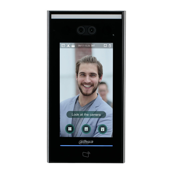
Homepage Table 3-1 Homepage description Description Unlock methods: Card, face, fingerprint, and password. When card, face, fingerprint, and password are all set as unlock mode, the password icon will not be displayed at the upper-left corner of the access controller. Date &... -
Page 21: Card
3.3.1 Card Put the card at the card swiping area to unlock the door. 3.3.2 Face Make sure that your face is centered on the face recognition frame, and then you can unlock the door. 3.3.3 Fingerprint Place your fingerprint at the fingerprint sensor to unlock the door. 3.3.4 User Password Enter the user passwords, and then you can unlock the door. - Page 22 Administrator login Select a main menu entering method.
-
Page 23: User Management
Main Menu User Management You can add new users, view user lists, admin lists, and change the administrator password on the User interface. 3.5.1 Adding New Users You can add new users by entering user IDs, names, importing fingerprints, face images, cards, passwords, selecting user levels, and more. - Page 24 New User Info Configure parameters on the interface. Table 3-2 New user parameter description Parameter Description . The IDs can be numbers, letters, and their combinations, ID that helps identify the user User ID and the maximum length of the ID is 32 characters. You can enter names with at most 32 characters (including numbers, symbols, and Name letters).
-
Page 25: Viewing User Information
Parameter Description You can register five cards for each user. On the card registration interface, enter your card number or swipe your card, and then the card information will be read by the access controller You can enable the Duress Card function on the card registration interface. After Card enabling the duress function, an alarm will be triggered if a duress card is used to unlock the door. -
Page 26: Period Management
3.6.1 Period Management You can set periods, holiday periods, holiday plan periods, door normally on periods, door normally closed periods, and remote verification periods. 3.6.1.1 Period Config You can configure 128 periods (weeks) whose number range is 0–127. You can set four periods on each day of a period (week). -
Page 27: Unlock
means enabled. means not enabled. 3.6.2 Unlock There are three unlock modes: Unlock mode, unlock by period, and group combination. Unlock modes vary with controller access models, and the actual controller access shall prevail. 3.6.2.1 Unlock Mode When the Unlock Mode is on, users can unlock through cards, fingerprints, faces, passwords, or any one of all the unlocking methods. - Page 28 Select a combination mode. + And means "and". For example, if you selected card + FP, it means, to unlock the door, you need to swipe your card first, and then get your fingerprint scanned. / Or means "or". For example, if you selected card/FP, it means, to unlock the door, you ...
- Page 29 to save the settings. Enable the Unlock by Period function. means enabled. means not enabled. 3.6.2.3 Group Combination Doors can only be unlocked by a group or groups that consist of more than two users if the Group Combination is enabled.
-
Page 30: Alarm Configuration
Parameter Description Valid users are the ones that have unlock permission. Doors can be unlocked only when the number of users to unlock the doors equals the number valid users. Valid users cannot exceed the total number of users in a group. Valid User If valid users equal total users in a group, doors can only be unlocked by all the users in the group. -
Page 31: Door Status
Table 3-4 Parameters on the alarm interface Parameter Description If a person unlocks the door with the identity checked by the access controller, but when the person gets out without getting the identity checked by the access controller, an alarm will be triggered and the person Anti-passback will have no authority to unlock the door any more. -
Page 32: Ip Address
3.7.1 IP Address 3.7.1.1 IP Configuration Configure an IP address for the access controller and connect it to the network. IP address configuration Table 3-5 IP configuration parameters Parameter Description NIC 1/2 Tap to configure parameters for the Ethernet port. IP Address/Subnet The IP address, subnet mask, and gateway IP address must be on the same Mask/Gateway... -
Page 33: Serial Port Settings
Because configurations can be cleared on the management platform, and the access controller can be initialized, you need to protect the platform access permission in case of data loss caused by improper operation. For active register parameter, see the table below. Table 3-6 Active register Name Parameter... -
Page 34: Wiegand Configuration
3.7.3 Wiegand Configuration Select Weigand Input or Weigand Output according to the entering direction and exiting direction. Select Connection > Weigand. Weigand Select Weigand Input when an external card swipe mechanism is connected to the access controller. Select Weigand Output when the access controller works as a reader that can be connected to ... -
Page 35: Face Parameter
3.8.2 Face Parameter Face parameter Tap a parameter and do configuration, and then tap Table 3-8 Face parameter Name Description Face Recognition Face recognition accuracy can be adjusted. The larger the value is, the Threshold higher the accuracy will be. Max. -
Page 36: Fill Light Brightness Setting
normally off; otherwise, the fill light will be on. NO: The fill light is normally on. NC: The fill light is normally closed. 3.8.4 Fill Light Brightness Setting You can select fill light brightness according to your needs. 3.8.5 Volume Adjustment You can adjust the beeping and voice volume. -
Page 37: Usb
Make sure that the USB is inserted before exporting user information and updating. During exporting or updating, do not pull out the USB or do other operations; otherwise the exporting or updating will fail. You need to import information from one access controller to the USB before using USB to import ... -
Page 38: Usb Import
3.9.2 USB Import Only data in the USB that was exported from one access controller can be imported into another access controller. Select USB > USB Import. USB Import Select the data type that you want to import. Tap OK. Data in the USB flash drive will be imported into the access controller. - Page 39 Features Table 3-9 Feature description Parameter Description Privacy Setting See "3.9.5 Privacy Setting" for details. If the third party card reader needs to be connected to the access through the wiegand output port, you need to enable the Card controller Card No.
-
Page 40: Privacy Setting
3.9.5 Privacy Setting Privacy setting Table 3-10 Features Parameter Description PWD Reset If the PWD Reset Enable function is enabled, you can reset the password. Enable The PWD Reset function is enabled by default. Hypertext Transfer Protocol Secure (HTTPS) is a protocol for secure communication over a computer network. -
Page 41: Result Feedback
Parameter Description Secure Shell (SSH) is a cryptographic network protocol for operating network services securely over an unsecured network. When SSH is enabled, SSH provides cryptographic service for the data transmission. If you select OFF for Fingerprint (FP), users’ fingerprint information will not be displayed when they get fingerprints recorded or when they use fingerprints to unlock the door. - Page 42 User Photo & Name User photo & name Only Name Only name...
-
Page 43: Record
Success or Failure Success or failure Record You can search for all unlocking records. Select Record > Search Punch Records. -
Page 44: Auto Test
Search punch records Auto Test When you use the access controller for the first time or when the access controller malfunctioned, you can use auto test function to check whether the access controller can work normally. Perform actions according to the prompts. -
Page 45: System Info
Auto test When you select Auto Test, the access controller will guide you to do all the auto tests. System Info You can view data capacity, device version, and hardware version of the access controller on the System Info interface. -
Page 46: Web Operation
Web Operation The access controller can be configured and operated on the web. Through the web you can set network parameters, video parameters, and access controller parameters; and you can also maintain and update the system. Initialization You need to set a password and an email address before logging in to the web for the first time. Open IE web browser, and enter the IP address (the default address is 192.168.1.108) of the access controller in the address bar, and then press the Enter key. - Page 47 Click Next. Auto check (Optional) Select Auto Check. It is recommended that Auto Check be selected to get the latest program in time. Click Next. The configuration is finished. Finished configuration Click Complete, and the initialization is completed.
-
Page 48: Login
Login Open IE web browser, enter the IP address of the access controller in the address bar, and press Enter. IE 8 and later are supported. Otherwise you might not log in to the web. Make sure that the computer used to log in to the web is in the same LAN with the device. ... - Page 49 Tips Read the tips and click OK. Reset Password Scan the QR code on the interface, and you will get the security code. At most two security codes will be generated by scanning the same QR code. If security codes become invalid, to get more security codes, refresh the QR code.
-
Page 50: Alarm Linkage
frozen for five minutes. Enter the security code you have received. Click Next. Reset and confirm the new password. The password should consist of 8 to 32 non-blank characters and contain at least two types of characters among upper case, lower case, number, and special character (excluding ' " ; : &). Click OK, and the reset is completed. - Page 51 Modify alarm linkage parameter Table 4-1 Alarm linkage parameter description Parameter Description Alarm Input You cannot edit the value. Keep it default. Name Enter a zone name. There are two options: NO and NC. Alarm Input Type If alarm input type of the alarm device you purchased is NO, then you should select NO;...
-
Page 52: Alarm Log
4.4.2 Alarm Log You can view the alarm type and time range in the Alarm Log interface. Select Alarm Linkage > Alarm Log. Alarm log Select a time range and alarm type, and then click Query. Query results Call Configuration The access controller can work as a door station and call other devices. - Page 53 Configure the parameters. Local (1) Table 4-2 Parameter description Parameter Description Device Type The access controller can only work as a unit door station. Enter a number to be identified by the management center. It should be Centre Call No. "888888"...
-
Page 54: Sip Server
Parameter Description Mode1: Real-time call but the video and sound may be lagging with poor Transmission network. Mode Mode2: Not real-time call but ensures smooth video and sound. 4.5.2 SIP Server On the web, you can add door stations and indoor stations to the SIP server so that they can talk to each other. -
Page 55: Door Station Management
4.5.2.2 Other Device as SIP Server Log in to the web. Select Talkback Setting > SIP Server. Do not enable SIP Server and select Server Type as VTO. Configure the parameters. SIP server (2) Table 4-4 SIP server parameter description (1) Parameter Description IP Address... - Page 56 Log in to the web. Select Talkback Setting > VTO No. Management. Click Add. VTO No. management Configure the parameters. Add a door station Table 4-5 Parameter description Parameter Description Rec No. Number of the door station. Register Password Keep the default value.
-
Page 57: Indoor Monitor Management
Parameter Description Build No. Cannot be configured. Unit No. Cannot be configured. IP Address IP address of the door station. Username Web login username and password for the door station. Password Click OK. 4.5.4 Indoor Monitor Management When the access controller works as the SIP server, add all relevant indoor monitors to call them. When there are main and extension indoor monitors, you need to enable group call function first before adding them. - Page 58 Add one indoor monitor Table 4-6 Parameter description Parameter Description First Name Last Name To differentiate each indoor monitor. Nick Name Room number of the indoor monitor. It can contain up to five digits and must be the same as the one ...
-
Page 59: Configuring The Managing Device
Click Add. Add indoor monitors in batches 4.5.5 Configuring the Managing Device When the access controller works as the SIP server, add other managing devices to call them. Log in to the web. Select Talkback Setting > VTS Management. Click Add. Add managing devices Enter the information. -
Page 60: Online Status
Added a managing device Modify a managing device. You need to update the information when the register password or IP address of the managing device changes. Click and enter the new password or IP address, and then click OK. Delete a managing device. -
Page 61: Call Logs
4.5.7 Call Logs You can check up to 1024 call logs. Log in to the web. Select Talkback Setting > Call. (Optional) Click Export Data to export all the logs. Call logs Data Capacity You can see how many users, cards, face images, and fingerprints the access controller can hold on the Data Capacity interface. -
Page 62: Video Setting
Video Setting You can set parameters including data rate, image parameters (brightness, contrast, hue, saturation, and more), and exposure on the Video Setting interface. 4.7.1 Data Rate Data rate Table 4-7 Data rate parameter description Parameter Description Video Standard There are two options: NTSC and PAL. Select a standard according to the video standard of your region. -
Page 63: Image
Parameter Description The number of bits that are conveyed or processed per unit of time. Bit Rate There are options: 512 Kbps, 640 Kbps, 768 Kbps, 896 Kbps, 1024 Kbps, 1.25 Mbps, 1.5 Mbps, 1.75 Mbps, and 2 Mbps. 4.7.2 Image There are two channels, and you need to configure parameters for each channel. -
Page 64: Exposure
Parameter Description Close: Without back light. BLC: Backlight compensation corrects regions with extremely high or low levels of light to maintain a normal and usable level of light for the object in focus. WDR: In the wide dynamic range mode, the system dims bright areas and compensates dark areas to ensure the definition of objects in the bright areas and dark areas. -
Page 65: Motion Detection
Parameter Description When you select Outdoor in the Anti-flicker drop-down list, you can select Shutter Priority as the exposure mode. Exposure modes of different devices might vary, and the actual product shall prevail. You can select from: Auto: The access controller will automatically adjust brightness of Exposure Mode images. -
Page 66: Volume Setting
Press and hold the left mouse button, and then drag the mouse in the red area. The motion detection area is displayed. The red rectangles are motion detection area. The default motion detection range is all the rectangles. To draw a motion detection area, you need to click Remove All first. ... -
Page 67: Image Mode
4.7.6 Image Mode There are three options: indoor, outdoor and other. Select Indoor when the access controller is installed indoors; select Outdoor when the access controller is installed outdoors; and select Other when the access controller is installed at places with backlights like corridors and hallways. Image mode 4.7.7 Local Coding Set up the area to be displayed on the indoor monitors. -
Page 68: Face Detect
Click OK. Face Detect You can configure human face related parameters on this interface to increase the accuracy of the face recognition. Select Face Detect. Face detect Configure the parameters. Table 4-10 Face detect parameter description Parameter Description Face Recognition The larger the value is, the higher the accuracy will be. -
Page 69: Network Setting
Parameter Description the access controller and gets the face recognized, the controller will prompt that face recognition failed. The prompt interval is called recognition timeout. When a face has no access authority stands in front of the access Invalid Face Prompt controller, the controller will prompt that the face is invalid. - Page 70 TCP/IP Configure parameters. Table 4-11 TCP/IP Parameter Description IP Version There is one option: IPv4. Ethernet Card Select to configure parameters of the card. MAC Address MAC address of the access controller. Static Set IP address, subnet mask, and gateway address manually. DHCP ...
-
Page 71: Port
4.9.2 Port Set the maximum connections clients that the access controller can be connected to and port numbers. Select Network Setting > Port. Configure port numbers. See the following table. Except max connection, you need to reboot the access controller to make the configuration effective after modifying values. -
Page 72: Date Setting
If you are to use P2P, you must connect the access controller to external network; otherwise the access controller cannot be used. Select Network Setting > P2P. Select Enable to enable P2P function. Click OK to complete the setting. Scan the QR code on your web interface to get the serial number of the access controller. Date Setting You need to set time zone, time, DST, and NTP for the access controller. -
Page 73: Safety Management
Date Setting Set parameters. Table 4-14 Date setting Parameter Description Time Zone Select time zone as needed. You can set system time manually, or you can click Sync with PC, to System Time scynchronize access controller time with the computer time. 1. -
Page 74: Systems
IP authority 4.11.2 Systems 4.11.2.1 System Service There are four options: SSH, PWD Reset Enable, CGI, and HTTPS. Refer to "3.9.4 Features” to select one or more than one of them. The system service configuration done on the web page and the configuration on the Features interface of the access controller will be synchronized. -
Page 75: User Management
4.11.2.2 Creating Server Certificate Click Create Server Certificate, enter needed information, click Save, and then the access controller will reboot. 4.11.2.3 Downloading Root Certificate Click Download Root Certificate. Select a path to save the certificate on the Save File dialog box. Double-click on the Root Certificate that you have downloaded to install the certificate. -
Page 76: Maintenance
facilitating the development and use of a global open standard for the interface of physical IP-based security products. When ONVIF is used, administrator, operator, and user have different permission of ONVIF server. Create onvif users as needed. Onvif user Maintenance You can make the access controller reboot itself in idle time to improve the running speed of the access controller. -
Page 77: Config Mgmt
4.14.1 Config Mgmt. When more than one access controller needs the same configuration, you can configure parameters for them by importing or exporting configuration files. Configuration management 4.14.2 Wiegand Serial Port Setting Select Wiegand/serial port setting as needed. For details, see "3.7.2 Serial Port Settings" and "3.7.3 Wiegand Configuration."... -
Page 78: Version Information
4.15.1 Version Information You can view information including MAC address, serial number, MCU version, web version, security baseline version, and system version. 4.15.2 Online User You can view username, IP address, and user login time on the Online User interface. Online user System Log You can view and backup the system log on the System Log interface. -
Page 79: Querying Logs
System log 4.16.1 Querying Logs Select a time range and its type, click Query, and logs meet the conditions will be displayed. 4.16.2 Backup Logs Click Backup to back up the logs displayed. Admin Log Enter Admin ID on the Admin Log interface, click Query, and then you will see the administrator’s operation records. -
Page 80: Exit
Admin log Hover the mouse cursor over , and then you can see detailed information of the current user. Exit , click OK, and then you will log out the web interface. Click... -
Page 81: Smart Pss Configuration
Smart PSS Configuration You can do access permission configuration to a single door or door groups through the Smart PSS client. For detailed configurations, see the Smart PSS user manual. Smart PSS interfaces might vary with versions, and the actual interface shall prevail. Login Install the Smart PSS (the default username is admin, and the default password is admin123), double- click... -
Page 82: Manual Add
Auto search Click Auto Search, enter the network segment, and then click Search. A list will be displayed. Select access controllers that you want to add to the Smart PSS, and then click Add, the Login information dialog box will be displayed. Enter the username and the login password to login. -
Page 83: Adding Users
Manual add Click Add on the Devices interface, and the Manual Add interface will be displayed. Enter the Device Name, select a method to add, enter the IP/Domain Name, Port number (37777 by default), Group Name, User Name, and Password. Click Add, and then you can see the added access controller on the Devices interface. -
Page 84: Card Type Selection
5.3.1 Card Type Selection Card types must be the same as card issuer types; otherwise card numbers cannot be read. On the Access interface, click , then click the IC or ID card icon, and then select a card type. There are two options: ID Card and IC Card. -
Page 85: Adding One User
Access Setting card type 5.3.2 Adding One User You can add users one by one. On the Access interface, click , then click , and then enter user’s information. Click Finish to complete the user adding. - Page 86 Access Add user...
-
Page 87: Adding Door Group
Adding Door Group You can manage doors by grouping doors. On the Access interface, click , click Add, enter door group name, and then select a time zone. Click Finish to complete the user adding. Access... -
Page 88: Access Permission Configuration
Add door group Access Permission Configuration You can do access permission configuration. There are two options: door group access permission and user access permission. Information of users who are given access permission in the Smart PSS and access controllers will be synchronized. 5.5.1 Giving Permission by Door Group Select a door group, add users to the door list, and then users on the door list get access permissions of all doors on the door list. - Page 89 Access User select On the Access interface, click , click Add, and click Door Group Permission. Click . Select user department in the dropdown list, or enter user ID/Name, and then...
-
Page 90: Giving Permission By User Id
search users. Select users from the users you found. Click Finish to complete the configuration. Users without user ID cannot be found. 5.5.2 Giving Permission by User ID You can give access permission to a user by selecting a user, and then select door groups for the user. Access... - Page 91 Select door group On the Access interface, click Click . The Select Door Group interface is displayed. Select user department in the dropdown list, or enter user ID/Name, and then select a door list. Click Finish.
-
Page 92: Cybersecurity Recommendations
Cybersecurity Recommendations Cybersecurity is more than just a buzzword: it’s something that pertains to every device that is connected to the internet. IP video surveillance is not immune to cyber risks, but taking basic steps toward protecting and strengthening networks and networked appliances will make them less susceptible to attacks. - Page 93 We suggest you to enable HTTPS, so that you visit Web service through a secure communication channel. MAC Address Binding We recommend you to bind the IP and MAC address of the gateway to the device, thus reducing the risk of ARP spoofing. Assign Accounts and Privileges Reasonably According to business and management requirements, reasonably add users and assign a minimum set of permissions to them.
Need help?
Do you have a question about the ASI7214X and is the answer not in the manual?
Questions and answers
hOW DO I SETUP MACHINE TO SHOW SHIFTS FOR PREVIOUS DAYS