Table of Contents
Advertisement
Quick Links
User Manual
SmartBond Production Line Tool
UM-B-041
Abstract
This document describes the SmartBond Production Line Tool (PLT) for DA1470x wireless SoC
family of products. The various software applications, as well as the PLT hardware are explained in
detail. The purpose of this document is to guide users on how to use the various PLT components.
Advertisement
Table of Contents

Related Manuals for Renesas SmartBond UM-B-041


Summary of Contents for Renesas SmartBond UM-B-041
-
Page 1: Abstract
User Manual SmartBond Production Line Tool UM-B-041 Abstract This document describes the SmartBond Production Line Tool (PLT) for DA1470x wireless SoC family of products. The various software applications, as well as the PLT hardware are explained in detail. The purpose of this document is to guide users on how to use the various PLT components. -
Page 2: Table Of Contents
6.10 Custom Memory Data ......................44 6.10.1 Custom Data CSV File Format ................45 6.11 Golden Unit Scan Test ......................46 6.12 Creating PLT Firmware Files ....................47 User Manual Revision 4.8 02-Nov-2022 © 2022 Renesas Electronics CFR0012 2 of 170... - Page 3 Appendix E Suggestions about Hardware and Cabling .............. 123 Appendix F RF Path Losses Calibration ..................126 Prerequisites ........................126 Setup ..........................127 Procedure .......................... 129 Appendix G Mkimage.exe ....................... 135 User Manual Revision 4.8 02-Nov-2022 © 2022 Renesas Electronics CFR0012 3 of 170...
-
Page 4: Figures
Figure 25: Golden Unit Scan Test Example Parameters ..............46 Figure 26: Firmware Files ........................47 Figure 27: Folder Contents of ‘fw_files’ ....................47 Figure 28: CFG PLT Startup Screen ....................49 User Manual Revision 4.8 02-Nov-2022 © 2022 Renesas Electronics CFR0012 4 of 170... - Page 5 Figure 81: DUT Log File ........................96 Figure 82: CSV File ..........................97 Figure 83: CLI Software Start Screen ....................98 Figure 84: CLI PLT Print Settings (x Command) ................100 User Manual Revision 4.8 02-Nov-2022 © 2022 Renesas Electronics CFR0012 5 of 170...
- Page 6 Figure 123: Location of Pull-Down Resistors ..................138 Figure 124: Anti-Ringing Solution ...................... 139 Figure 125: DA1470x Pro Motherboard DK Wiring ................141 Figure 127: Example CSV Log File ....................153 User Manual Revision 4.8 02-Nov-2022 © 2022 Renesas Electronics CFR0012 6 of 170...
-
Page 7: Tables
Table 52: QSPI Flash Erase ........................ 79 Table 53: Flash Image Write ....................... 80 Table 54: Memory Read Test ......................80 Table 55: Custom Memory Data ......................81 User Manual Revision 4.8 02-Nov-2022 © 2022 Renesas Electronics CFR0012 7 of 170... - Page 8 Table 77: CSV File Contents ......................149 Table 79: Example CSV Log File Content Analysis ................153 Table 81: DUT Status Codes ......................157 Table 82: Golden Unit Status Codes ....................166 User Manual Revision 4.8 02-Nov-2022 © 2022 Renesas Electronics CFR0012 8 of 170...
-
Page 9: Terms And Definitions
Packet Error Rate Production Line Tool PLTD Production Line Tool DLL Power-On Reset Random-Access Memory Resistor Crystal Oscillator Radio Frequency Receive SCPI Standard Commands for Programmable Instruments System-on-Chip User Manual Revision 4.8 02-Nov-2022 © 2022 Renesas Electronics CFR0012 9 of 170... - Page 10 Transmit UART Universal Asynchronous Receiver/Transmitter User Interface Universal Serial Bus VISA Virtual Instrument Software Architecture Programming Supply Voltage (pin) Extensible Markup Language XTAL Crystal XML Schema Definition User Manual Revision 4.8 02-Nov-2022 © 2022 Renesas Electronics CFR0012 10 of 170...
-
Page 11: References
UM-B-041 SmartBond Production Line Tool References UM-B-040, DA1458x/DA1468x Production Line Tool Libraries v4.2, User manual, Renesas UM-B-014, DA1458x Bluetooth Smart Development Kit - Expert, User Manual, Renesas FT4232H – Hi-Speed Quad USB UART IC, FTDI Chip FT232 – USB UART... -
Page 12: New Version Features
OTP CS and applied in XTAL32M_TRIM_REG (0x50050408) DA1470x register. Operation adds less than 1sec extra delay but has great benefits in overall product sleep and thus power performance. User Manual Revision 4.8 02-Nov-2022 © 2022 Renesas Electronics CFR0012 12 of 170... - Page 13 Low level debug logs are flushed continuously. No need to close Low level debug log files flush the application executable anymore for the log files to be updated. User Manual Revision 4.8 02-Nov-2022 © 2022 Renesas Electronics CFR0012 13 of 170...
-
Page 14: Introduction
5. Burn the OTP header. ® 6. Perform Scan test. Reset the DUTs and set the GU to scan for the DUT Bluetooth advertisements. Figure 1: Production Line Tool Hardware User Manual Revision 4.8 02-Nov-2022 © 2022 Renesas Electronics CFR0012 14 of 170... -
Page 15: Hardware
4x URX/UTX Commands XTAL trim pulse VPP Enable CPLD VBAT Enable URX/UTX URX/UTX URX/UTX URX/UTX DUT1 DUT2 DUT3 DUT16 Figure 2: Production Line Tool Hardware Board Block Diagram User Manual Revision 4.8 02-Nov-2022 © 2022 Renesas Electronics CFR0012 15 of 170... -
Page 16: Printed Circuit Board Layout
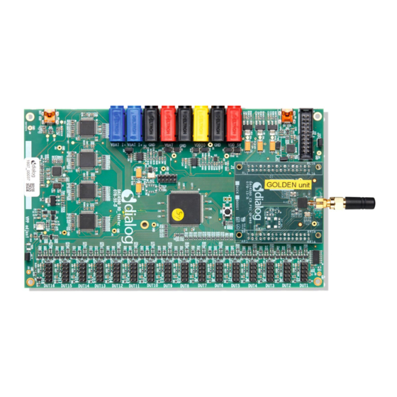
Current jumper GU reset CPLD prog. socket Golden Unit CPLD adjust Antenna or SMA cable jumper 16x DUTs Figure 3: Top View of the PLT Hardware Board User Manual Revision 4.8 02-Nov-2022 © 2022 Renesas Electronics CFR0012 16 of 170... -
Page 17: Plt Power Supply
Pulse not used not used not used DUT TX Only DA14580/1/2/3 DUT RX (pinning 100 mil) DUT RX DUT TX Figure 5: Production Line Tool DUT Connections User Manual Revision 4.8 02-Nov-2022 © 2022 Renesas Electronics CFR0012 17 of 170... -
Page 18: Data Streaming
DUT- UART x(x) l(x) u(x) DUT- Reset ‘1’ & 1 * Virtual COM-PORT t(0...3) Golden p(0/1) PC USB Unit r(xx) Figure 6: CPLD UART Data Streams User Manual Revision 4.8 02-Nov-2022 © 2022 Renesas Electronics CFR0012 18 of 170... -
Page 19: Crystal Trimming
Note: The CPLD is also used to switch the UART signals between the QUAD FTDIs and the DUTs. When the VBAT is switched off and the UART wires are not disconnected, a ‘rest voltage’ may be User Manual Revision 4.8 02-Nov-2022 © 2022 Renesas Electronics CFR0012 19 of 170... -
Page 20: Golden Unit
Making pin DTR low for a short period of time will reset the GU. Every time the PLT tests start, a hardware reset is issued to the Golden Unit. Jumper J47 should be ON and J46 OFF for this reset method to operate. User Manual Revision 4.8 02-Nov-2022 © 2022 Renesas Electronics CFR0012 20 of 170... -
Page 21: Current Measurements
(e.g., each one with its own battery) the current measurement procedure cannot be used. Figure 11: VBAT DUT Current Measurement Setup Jumper Settings This section describes the PLT hardware jumper settings. User Manual Revision 4.8 02-Nov-2022 © 2022 Renesas Electronics CFR0012 21 of 170... -
Page 22: J26 - Current Measurements
10. In this way, the PLT software will control the GU hardware reset. Figure 13 shows the jumper placement on the actual PCB. Figure 13: Location of J46 Jumper User Manual Revision 4.8 02-Nov-2022 © 2022 Renesas Electronics CFR0012 22 of 170... -
Page 23: J37 - Gu Programming
Figure 16 shows the location of jumper J37 on the PLT PCB. Figure 15: J37 - GU Programming Jumper Schematics Figure 16: Location of J37 Jumper User Manual Revision 4.8 02-Nov-2022 © 2022 Renesas Electronics CFR0012 23 of 170... -
Page 24: Plt Functional Blocks
DUT 13 DUT 14 DUT 15 12MHz DUT 16 Xtal USB UART Golden Unit Power 6.7V Vbat Vbat DUTs VDDIO VDDIO CPLD Figure 17: PLT Functional Blocks User Manual Revision 4.8 02-Nov-2022 © 2022 Renesas Electronics CFR0012 24 of 170... -
Page 25: Software
User Interface ble_tester_ mt8852b.dll driver.dll Core DLLs DA1470x firmware Instruments uartboot.bin, st_fw.bin IQxelM.dll User defined extensions Figure 18: Production Line Tool Software Block Diagram User Manual Revision 4.8 02-Nov-2022 © 2022 Renesas Electronics CFR0012 25 of 170... -
Page 26: Software Package Contents
This is the DLL for taking current measurements using ammeter_instr_plugins/ammeter_scpi.dll a DMM that supports the standard SCPI commands. NI- VISA is also used for this purpose. Example DMM User Manual Revision 4.8 02-Nov-2022 © 2022 Renesas Electronics CFR0012 26 of 170... - Page 27 The ni_usb_tc01.dll is the DLL used to interface a NI temp_meas_instr_plugins/ni_usb_tc01.dll USB TC01 Ref. temperature sensor for temperature measurements. The tmu_temp_sens.dll is the DLL used to interface a temp_meas_instr_plugins/tmu_temp_sens.dll Papouch TMU sensor Ref. for temperature measurements. User Manual Revision 4.8 02-Nov-2022 © 2022 Renesas Electronics CFR0012 27 of 170...
- Page 28 32 and 64-bit machines. For installing these, users should agree to the license vc_redist.x86.exe/vc_redist.x64.exe requirements described during the installation of any of these packages. It is also found here: https://www.visualstudio.com/license-terms/mt171551/. User Manual Revision 4.8 02-Nov-2022 © 2022 Renesas Electronics CFR0012 28 of 170...
-
Page 29: Prerequisites
Used for instrument control, like Bluetooth LE tester and DMM. NI-488.2 15.5 can be downloaded from http://www.ni.com/download/ni-488.2-15.5/5859/en/ Used for optional instrument control like temperature NI-DAQmx measurements using the NI USB TC01 sensor. User Manual Revision 4.8 02-Nov-2022 © 2022 Renesas Electronics CFR0012 29 of 170... -
Page 30: System Requirements
Special care should be taken to work with multiple PLT hardware and software. Most probably, two different BD address files should be used for each PLT hardware. User Manual Revision 4.8 02-Nov-2022 © 2022 Renesas Electronics CFR0012 30 of 170... -
Page 31: Building The Code
Go to folder 'source\production_line_tool'. The following files and folders should exist. Double click the production_line_tool.sln Visual Studio 2017 Express solution file. The Visual Studio 2017 Express application will start and the PLT Solution Explorer should be shown. User Manual Revision 4.8 02-Nov-2022 © 2022 Renesas Electronics CFR0012 31 of 170... - Page 32 Note: There is no need to unload any projects for the solution to be built. This was fixed in PLT v4.4 and onwards by dynamically linking DLLs. User Manual Revision 4.8 02-Nov-2022 © 2022 Renesas Electronics CFR0012 32 of 170...
-
Page 33: Executing The Applications
Download the latest PLT software package (e.g., SmartBond_PLT_v_x.x.zip). Extract the software package. The following two folders should exist. Go to folder 'executables'. This folder should contain the following files and sub-folders. User Manual Revision 4.8 02-Nov-2022 © 2022 Renesas Electronics CFR0012 33 of 170... - Page 34 GU USB cable is not connected to the PC. Press 'OK' if the warning message appears. The application will start, and the initial Hardware Setup screen will be shown. User Manual Revision 4.8 02-Nov-2022 © 2022 Renesas Electronics CFR0012 34 of 170...
-
Page 35: Table 11: Smartbond_Plt_Gui.exe Application Execution
See Table 10. Go to folder 'executables'. This folder should contain the following files and sub-folders. Double click on SmartBond_PLT_GUI.exe. User Manual Revision 4.8 02-Nov-2022 © 2022 Renesas Electronics CFR0012 35 of 170... - Page 36 The following initial screen will appear. By clicking the keyboard spacebar, the START button will be pressed and the preconfigured tests and memory actions will start to be executed. User Manual Revision 4.8 02-Nov-2022 © 2022 Renesas Electronics CFR0012 36 of 170...
-
Page 37: Table 12: Smartbond_Plt_Cli.exe Application Execution
GU_fw_upgrade.exe can be started by either opening the application from the executables folder or by pressing the ‘Upgrade GU Firmware’ button in the PLT Hardware Setup tab in SmartBond_PLT_CFG.exe. User Manual Revision 4.8 02-Nov-2022 © 2022 Renesas Electronics CFR0012 37 of 170... - Page 38 Double click the GU_fw_upgrade.exe application executable. The following initial screen will appear. Follow the instructions to guide you to successfully configure and select the Golden Unit. A detailed procedure is explained in Section 7.5. User Manual Revision 4.8 02-Nov-2022 © 2022 Renesas Electronics CFR0012 38 of 170...
-
Page 39: Test Sequence
Get uartboot_da1470x.bin After uartboot_da1470x.bin has been downloaded, version. commands can be sent to it. A command to get the uartboot_da1470x.bin firmware version is sent to the devices. User Manual Revision 4.8 02-Nov-2022 © 2022 Renesas Electronics CFR0012 39 of 170... - Page 40 GPIO/LED Perform the GPIO/LED test, if the test is active. GPIO connection test Perform a GPIO continuity or voltage level test if the test is active. User Manual Revision 4.8 02-Nov-2022 © 2022 Renesas Electronics CFR0012 40 of 170...
- Page 41 The PLT expects to find devices in the air with the BD addresses programmed by the same tool, so it can match the BD addresses returned by the GU. User Manual Revision 4.8 02-Nov-2022 © 2022 Renesas Electronics CFR0012 41 of 170...
-
Page 42: Figure 20: Da1470X Test Sequence
OTP binary write OTP CS write Memory read Scan test memory write DUTs Memory Programming System initialization Single test Multiple tests External instrument Figure 20: DA1470x Test Sequence User Manual Revision 4.8 02-Nov-2022 © 2022 Renesas Electronics CFR0012 42 of 170... -
Page 43: Vbat/Reset Signals Operation
Since the DUTs will be powered through the PLT HW using the VBAT line, the Current Measurement Test (Table 46) for the DA1470x are supported as described in Section 5.7. User Manual Revision 4.8 02-Nov-2022 © 2022 Renesas Electronics CFR0012 43 of 170... -
Page 44: Vbat On With Reset
Users can provide a path to a CSV file that will contain the custom memory data for each DUT. The format of the CSV file is specific and is provided in Section 6.10.1. User Manual Revision 4.8 02-Nov-2022 © 2022 Renesas Electronics CFR0012 44 of 170... -
Page 45: Custom Data Csv File Format
The first operation is to write the OTP memory of the DA1470x DUTs four bytes, in OTP address 0x0000 (OTP user application area). ● The second operation is configured to write into the OSPI flash address 0x8000 sixteen bytes (0xA5A5A5A55A5A5A5ACDCDCDCDAFAFAFAF). User Manual Revision 4.8 02-Nov-2022 © 2022 Renesas Electronics CFR0012 45 of 170... -
Page 46: 6.11 Golden Unit Scan Test
Finally, the parameters DUT reboot time and DUT reboot difference set the DUT time needed to perform a POR with a small delay between the DUTs if needed. Figure 25: Golden Unit Scan Test Example Parameters User Manual Revision 4.8 02-Nov-2022 © 2022 Renesas Electronics CFR0012 46 of 170... -
Page 47: 6.12 Creating Plt Firmware Files
The ‘fw_files’ folder has two main categories. Firmware targeted for the GU and for the DUTs. Under each category there is a folder indicating the IC target and the SDK used. Figure 27: Folder Contents of ‘fw_files’ User Manual Revision 4.8 02-Nov-2022 © 2022 Renesas Electronics CFR0012 47 of 170... -
Page 48: Golden Unit Firmware
‘QSPI_Release’ option for each chip. Each binary will be created under the project folder in a folder having the same name as the selected option. User Manual Revision 4.8 02-Nov-2022 © 2022 Renesas Electronics CFR0012 48 of 170... -
Page 49: Applications
If OK is pressed, the Hardware Setup tab will be loaded with the DUT 1 checkbox in red. The displayed value will be the default value taken from the XML schema document (params.xsd). User Manual Revision 4.8 02-Nov-2022 © 2022 Renesas Electronics CFR0012 49 of 170... -
Page 50: Figure 29: Cfg Plt With Erroneous Configuration Parameter
Saves the options of the selected tab. E.g. If General settings tab is selected, then only the settings for this tab will be saved. Note: A shortcut for this button is the Ctrl+S key combination. User Manual Revision 4.8 02-Nov-2022 © 2022 Renesas Electronics CFR0012 50 of 170... -
Page 51: Xml And Xsd Files
XSD entry that is used for the parameter validation. The cfg:hex_array_6_bytes type is defined later in the file and has a rather complicated pattern defined with <xs:pattern value User Manual Revision 4.8 02-Nov-2022 © 2022 Renesas Electronics CFR0012 51 of 170... -
Page 52: Hardware Setup
Users can select the device IC type. This option may change any IC related configuration parameters and their equivalent graphics, such as selectable tabs and tests. Table 19 describes the available options for the Device IC. User Manual Revision 4.8 02-Nov-2022 © 2022 Renesas Electronics CFR0012 52 of 170... -
Page 53: Figure 33: Active Duts
DUT COM Ports. Table 21: DUT COM Ports Option Description DUT1-16 Shows the Widows COM port assigned to a specific DUT. Reset Sets all values to zero. User Manual Revision 4.8 02-Nov-2022 © 2022 Renesas Electronics CFR0012 53 of 170... -
Page 54: Figure 35: Golden Unit Com Port
Retrieves the current Bluetooth LE and application versions of the connected Golden Unit. Upgrade GU Firmware Opens the Section application, which is used to update the GU firmware. User Manual Revision 4.8 02-Nov-2022 © 2022 Renesas Electronics CFR0012 54 of 170... -
Page 55: General
Shows how many DUTs are still to be tested. This option is available only when Range mode is enabled in Section 7.2.4.1. Runs Shows the number of test-runs the PLT has performed. User Manual Revision 4.8 02-Nov-2022 © 2022 Renesas Electronics CFR0012 55 of 170... -
Page 56: Figure 38: Test Options
This setting controls the reset polarity as active high or active low. Test Settings. Memory Programming includes all the tests in Sections 7.2.7and 7.2.8. User Manual Revision 4.8 02-Nov-2022 © 2022 Renesas Electronics CFR0012 56 of 170... -
Page 57: Table 26: Test Options
The time to wait for the script to finish. Script path The path of file to execute when the Run script when testing is finished option is enabled. User Manual Revision 4.8 02-Nov-2022 © 2022 Renesas Electronics CFR0012 57 of 170... -
Page 58: Bd Addresses
Sine a ‘Start BD address’ and an ‘End BD address’ exist, the total amount of devices to be tested can be calculated. Therefore, this mode enables the Total and Left fields in Section 7.2.3.1, where Total User Manual Revision 4.8 02-Nov-2022 © 2022 Renesas Electronics CFR0012 58 of 170... -
Page 59: Figure 40: Example For Load From File Mode
The BD address from file that will be used in the first active DUT of the next PLT run. Path to the file that contains the BD addresses. Use button […] on the right to BD address file navigate and select a file. User Manual Revision 4.8 02-Nov-2022 © 2022 Renesas Electronics CFR0012 59 of 170... -
Page 60: Dut Hardware Setup
When this feature is enabled, PLT will send a command to the device to measure VBAT using its internal ADC. The VBAT level will then be logged. No, pass or fail limits exist for this test. It is only used for logging purposes. User Manual Revision 4.8 02-Nov-2022 © 2022 Renesas Electronics CFR0012 60 of 170... -
Page 61: Figure 44: Otp Timestamp Read
Test name The name assigned for this test. Select the GPIO that will be toggled. GPIO power level Sets the power level of the GPIOs. User Manual Revision 4.8 02-Nov-2022 © 2022 Renesas Electronics CFR0012 61 of 170... -
Page 62: Figure 47: Scan Dut Advertise Test
Note: When adding or removing a test all settings are refreshed with the values written to the XML file, meaning that any unsaved settings will be lost. Golden Unit Figure 49: Golden Unit RF Tests User Manual Revision 4.8 02-Nov-2022 © 2022 Renesas Electronics CFR0012 62 of 170... -
Page 63: Figure 49: Ble Tester General Settings
Table 35: BLE Tester General Settings Option Description Enable This option enables the BLE Tester tests, which include: ● ® Bluetooth LE Tester TX Power ● Frequency Offset User Manual Revision 4.8 02-Nov-2022 © 2022 Renesas Electronics CFR0012 63 of 170... -
Page 64: Figure 50: Ble Tester Tx Power
-12 dBm to -26 dBm ● -24 dBm to -35 dBm Default value is Auto. Tx Power The DUT transmit output power. -50 dBm to +6 dBm is supported. User Manual Revision 4.8 02-Nov-2022 © 2022 Renesas Electronics CFR0012 64 of 170... -
Page 65: Figure 51: Ble Tester Frequency Offset
-12 dBm to -26 dBm ● -24 dBm to -35 dBm Default value is Auto. Tx Power The DUT transmit output power. -50 dBm to +6 dBm is supported. User Manual Revision 4.8 02-Nov-2022 © 2022 Renesas Electronics CFR0012 65 of 170... -
Page 66: Figure 52: Ble Tester Modulation Index
+5 dBm to -7 dBm ● -4 dBm to -16 dBm ● -12 dBm to -26 dBm ● -24 dBm to -35 dBm Default value is Auto. User Manual Revision 4.8 02-Nov-2022 © 2022 Renesas Electronics CFR0012 66 of 170... -
Page 67: Figure 53: Ble Tester Rx Sensitivity
The number of packets the Bluetooth LE tester instrument to transmit. ® Tx power The TX output power of the Bluetooth LE tester instrument. Suggested values are 0 to -10 dBm. User Manual Revision 4.8 02-Nov-2022 © 2022 Renesas Electronics CFR0012 67 of 170... -
Page 68: Figure 54: Path Losses Per Dut
Note: When adding or removing a test, all settings are refreshed with the values written to the XML file, meaning that any unsaved settings will be lost. User Manual Revision 4.8 02-Nov-2022 © 2022 Renesas Electronics CFR0012 68 of 170... -
Page 69: Figure 56: Gpio Connection Test
Set Pin and the state to check. It will also check for shorts between given GPIOs. Table 42: GPIO Connection Test Option Description Enable This option enables the specific custom test. User Manual Revision 4.8 02-Nov-2022 © 2022 Renesas Electronics CFR0012 69 of 170... -
Page 70: Figure 57: Sensor Test (Spi)
Sets the GPIO state the test awaits to see in the Get Pin. This option is disabled if Get Pin level the Set Pin mode is enabled. 7.2.6.8 Sensor Test Figure 58: Sensor Test (SPI) User Manual Revision 4.8 02-Nov-2022 © 2022 Renesas Electronics CFR0012 70 of 170... -
Page 71: Figure 58: Sensor Test (I2C)
Select the GPIO to be used as a sensor interrupt. GPIO power level Sets the power level of the GPIOs. Expected data The received sensor byte that will be expected on a successful operation. User Manual Revision 4.8 02-Nov-2022 © 2022 Renesas Electronics CFR0012 71 of 170... -
Page 72: Figure 59: Custom Test
External 32 kHz Tests. Table 45: External 32 kHz Tests Options Option Description Enable This option enables the external 32 kHz low power clock test. User Manual Revision 4.8 02-Nov-2022 © 2022 Renesas Electronics CFR0012 72 of 170... -
Page 73: Figure 61: Current Measurement Tests
The ammeter can be connected in the blue banana plugs as described in Section or to an external power supply (if present) depending the selected VBAT/Reset Mode (Section 7.2.2.6). User Manual Revision 4.8 02-Nov-2022 © 2022 Renesas Electronics CFR0012 73 of 170... -
Page 74: Table 46: Current Measurement Tests
0 to 9999 and default value is 0.001 A. When the ammeter_scpi.dll is used, if this value is set to zero, the instrument will use the automatic range functionality. User Manual Revision 4.8 02-Nov-2022 © 2022 Renesas Electronics CFR0012 74 of 170... -
Page 75: Table 48: Current Measurement Test - Sleep Current Measurement
The value of the shunt resistor used for sleep current measurement. Applicable only if a voltmeter or a NI-DAQ is used to measure current instead of a DMM. Values from 0 to 9999 are supported. User Manual Revision 4.8 02-Nov-2022 © 2022 Renesas Electronics CFR0012 75 of 170... -
Page 76: Figure 62: Temperature Measurement Test
Figure 63: Temperature Measurement Test Table 49 describes the available options for the Temperature Measurement Test. Table 49: Temperature Measurement Test Option Description Enable This option enables the Temperature measurement test. User Manual Revision 4.8 02-Nov-2022 © 2022 Renesas Electronics CFR0012 76 of 170... -
Page 77: Figure 63: Scan Test
DUT reboot time The time the VBAT will remain low during the device reboot. This value is time in ms*100 (e.g., 15 is 1500 ms). User Manual Revision 4.8 02-Nov-2022 © 2022 Renesas Electronics CFR0012 77 of 170... -
Page 78: Memory Functions
Via this field, the user specifies the binary file to be burned into the OTP. A .bin Image path binary file of any name can be selected. User Manual Revision 4.8 02-Nov-2022 © 2022 Renesas Electronics CFR0012 78 of 170... -
Page 79: Figure 65: Flash Memory
After every QSPI/OQSPI Flash erase test has finished, the QSPI/OQSPI image write tests will begin. Table 53 describes the available options for the QSPI/OQSPI Flash Image Write operation. User Manual Revision 4.8 02-Nov-2022 © 2022 Renesas Electronics CFR0012 79 of 170... -
Page 80: Figure 66: Memory Read Test
PLT execution path. Memory type The type of memory to read the data from. Available options are OTP, QSPI FLASH and OQSPI FLASH. User Manual Revision 4.8 02-Nov-2022 © 2022 Renesas Electronics CFR0012 80 of 170... -
Page 81: Memory Header
OQSPI (only with Manual data). Start address (available with Memory address offset to begin burning the data. OTP user application valid address is 0x000 – 0xBFC. Manual data mode) User Manual Revision 4.8 02-Nov-2022 © 2022 Renesas Electronics CFR0012 81 of 170... - Page 82 SmartBond Production Line Tool Option Description Data size (available with The size of the memory data to burn. The size is number of bytes. Manual data mode) User Manual Revision 4.8 02-Nov-2022 © 2022 Renesas Electronics CFR0012 82 of 170...
-
Page 83: Figure 69: Otp Configuration Script
The OTP CS is an area used for programming system registers with values that are defined during production testing, store a trim value for the application software or define UART time out time during User Manual Revision 4.8 02-Nov-2022 © 2022 Renesas Electronics CFR0012 83 of 170... -
Page 84: Table 56: Otp Configuration Script Commands
The Development Mode command consists of one 32-bit word which is mode equal to 0xE7000000, instructing the booter to disable the development mode. There is no limitation for the number of entries the Development User Manual Revision 4.8 02-Nov-2022 © 2022 Renesas Electronics CFR0012 84 of 170... - Page 85 RR = 0xFF is reserved for customer use only. ○ RR = 0x00 will be used for Renesas parameters ○ RR = 0x01 – 0xEF are reserved for future use of Renesas parameters ● YY: indicates that 0xYY number of words will follow ●...
-
Page 86: Debug Settings
Enable error debug level messages. All debug print messages marked as error will be printed. Level - Info Enable info debug level messages. All debug print messages marked as info will be printed. User Manual Revision 4.8 02-Nov-2022 © 2022 Renesas Electronics CFR0012 86 of 170... -
Page 87: Security
Type the current password to enable changing of the following fields. Disable Password This option will disable the password usage. New Password Type a new password. Retype New Password Verify the new password. User Manual Revision 4.8 02-Nov-2022 © 2022 Renesas Electronics CFR0012 87 of 170... -
Page 88: Gui Plt Application
File > Open CSV file Contains a list with all the available CSV files to open. File > Exit Exits the GUI PLT application. User Manual Revision 4.8 02-Nov-2022 © 2022 Renesas Electronics CFR0012 88 of 170... - Page 89 Code: Real-time status as a PLTD DLL special code described in Ref. [1]. ● Description: A brief description of the status code. ● Result: Simplified color-coded status showing the progress per DUT. User Manual Revision 4.8 02-Nov-2022 © 2022 Renesas Electronics CFR0012 89 of 170...
- Page 90 This timer starts counting when the START button is pressed and runs until the PLT returns to its idle state, showing the approximate duration of the tests. User Manual Revision 4.8 02-Nov-2022 © 2022 Renesas Electronics CFR0012 90 of 170...
-
Page 91: Gui Plt Settings
By enabling this option, the GUI PLT will perform multiple procedures without Runs any delay between them. This is used for only for evaluation. Times The number of times to run. User Manual Revision 4.8 02-Nov-2022 © 2022 Renesas Electronics CFR0012 91 of 170... -
Page 92: Running The Gui Plt And Executing Tests
If any OTP burning test is scheduled, a pop-up message will inform the user and prompt to continue (Figure 76). Figure 76: GUI PLT OTP Burn Warning Message User Manual Revision 4.8 02-Nov-2022 © 2022 Renesas Electronics CFR0012 92 of 170... -
Page 93: Figure 76: Gui Plt Testing (1 Of 2)
DUT Log File (Section 7.3.4)to get more details about the parameters used, calculated values and the reason for failure in the case of an error. User Manual Revision 4.8 02-Nov-2022 © 2022 Renesas Electronics CFR0012 93 of 170... -
Page 94: Figure 77: Gui Plt Testing (2 Of 2)
(including the BD addresses) remain the same and only tests that failed are retested. At this time, the CSV File (Section 7.3.5) and all the DUT Log Files (Section 7.3.4) are updated. Figure 79: GUI PLT Tests Finished User Manual Revision 4.8 02-Nov-2022 © 2022 Renesas Electronics CFR0012 94 of 170... -
Page 95: Debug Console
Debug Console. Depending on the type of the message, a different color is used: DEBUG messages are light blue, INFO messages are white and ERROR messages are red. Figure 81: Debug Console User Manual Revision 4.8 02-Nov-2022 © 2022 Renesas Electronics CFR0012 95 of 170... -
Page 96: Dut Log File
DUT and a timestamp of the event. After the tests finish the header is updated with the end time of the test and the firmware versions, which were retrieved during testing. User Manual Revision 4.8 02-Nov-2022 © 2022 Renesas Electronics CFR0012 96 of 170... -
Page 97: Csv File
PLT software and hardware information are shown along with valuable DUT information. The CSV file keeps information about all the production tests of a single day. A new CSV file is created every day. User Manual Revision 4.8 02-Nov-2022 © 2022 Renesas Electronics CFR0012 97 of 170... -
Page 98: Cli Plt Application
Use this option to enable error and info prints. Choose file output or console output. Only the file option is currently supported. ● file Example: "d file" User Manual Revision 4.8 02-Nov-2022 © 2022 Renesas Electronics CFR0012 98 of 170... -
Page 99: Running The Cli And Executing Tests
There are several options to be called in order to make sure that the CLI PLT is set up correctly. Each of following commands is explained in Table User Manual Revision 4.8 02-Nov-2022 © 2022 Renesas Electronics CFR0012 99 of 170... -
Page 100: Figure 84: Cli Plt Print Settings (X Command)
DUTs with DUT 1 being the LSB. This command will replace the dut_num_x values in the configuration file. The following example will enable only DUT1, DUT2, DUT15 and DUT 16. User Manual Revision 4.8 02-Nov-2022 © 2022 Renesas Electronics CFR0012 100 of 170... - Page 101 After all the tests have finished, the result remains on the screen as shown in Figure 88. Figure 87: CLI PLT Testing Figure 88: CLI PLT Testing Finished User Manual Revision 4.8 02-Nov-2022 © 2022 Renesas Electronics CFR0012 101 of 170...
- Page 102 DUTs to use, with DUT 1 being the LSB. In the following example, the PLT hardware will be reset and DUTs 1, 2, 15 and 16 will be used. Example: >m 1C003 User Manual Revision 4.8 02-Nov-2022 © 2022 Renesas Electronics CFR0012 102 of 170...
-
Page 103: Using Cli Commands With Arguments
This BD address will be used in DUT1, as it is the only active DUT. 4. '-s': Perform the tests. BD address write in QSPI header should be enabled for the following test to pass. User Manual Revision 4.8 02-Nov-2022 © 2022 Renesas Electronics CFR0012 103 of 170... -
Page 104: Gu Upgrade Application
Cancel button or close the application using the X button from the windows bar at the top. Figure 90: GU Upgrade - Introduction Page User Manual Revision 4.8 02-Nov-2022 © 2022 Renesas Electronics CFR0012 104 of 170... -
Page 105: Hardware Version Screen
Connect the power supply of the PLT, as described in Section and connect the jumpers as shown Figure 95 where applicable. Adjust the jumpers as proposed by the tool. User Manual Revision 4.8 02-Nov-2022 © 2022 Renesas Electronics CFR0012 105 of 170... -
Page 106: Golden Unit Reset Screen
Golden Unit must be reset, to click the reset button located next to the Golden Unit on top of the PLT hardware. User Manual Revision 4.8 02-Nov-2022 © 2022 Renesas Electronics CFR0012 106 of 170... -
Page 107: Gu Com Port Screen
H. GU COM port can be also verified using the Check button. Selected GU COM port will be shown on the left bottom corner of the tool. User Manual Revision 4.8 02-Nov-2022 © 2022 Renesas Electronics CFR0012 107 of 170... -
Page 108: Burn Firmware Screen
Figure 99: GU FW Upgrade - Burn Firmware User Manual Revision 4.8 02-Nov-2022 © 2022 Renesas Electronics CFR0012 108 of 170... - Page 109 After the SPI flash program procedure is finished, a pop-up message appears with the result of the programming procedure. If the SPI flash was programmed successfully, the pop-up message will also show the version of the new Golden Unit firmware (Figure 100). User Manual Revision 4.8 02-Nov-2022 © 2022 Renesas Electronics CFR0012 109 of 170...
-
Page 110: Example Usage
Set a time for the Reset to stay active. VBAT/Reset Use VBAT On with Reset since it is faster to Mode reset DUTs rather that performing a POR with the VBAT signal. User Manual Revision 4.8 02-Nov-2022 © 2022 Renesas Electronics CFR0012 110 of 170... - Page 111 In Golden Unit: ● Check Enable ● Select 2424 MHz as frequency ● Set the RSSI limit to -70 dBm ● Set Packet error limit to 10% User Manual Revision 4.8 02-Nov-2022 © 2022 Renesas Electronics CFR0012 111 of 170...
- Page 112 Memory Functions ● Check Write enable Write 1 test ● Check OQSPI ● Check Verify Write ● Make sure pxp_reporter_da1470x.img is selected. GUI PLT Open GUI PLT User Manual Revision 4.8 02-Nov-2022 © 2022 Renesas Electronics CFR0012 112 of 170...
- Page 113 RAM and getting the version of the st_fw_da1470x.bin. This time is about 6 seconds. T2-T3 This time includes the production tests. The XTAL trim and the GU RF RSSI test. Time is about 4.3 seconds. User Manual Revision 4.8 02-Nov-2022 © 2022 Renesas Electronics CFR0012 113 of 170...
- Page 114 40 seconds. This is verified from both the DUT log file and the CSV log file. Both files are shown below. User Manual Revision 4.8 02-Nov-2022 © 2022 Renesas Electronics CFR0012 114 of 170...
-
Page 115: Appendix A Top View Of Plt Pcb Version D
UM-B-041 SmartBond Production Line Tool Appendix A Top View of PLT PCB Version D Figure 102: Top View of PLT PCB Version D User Manual Revision 4.8 02-Nov-2022 © 2022 Renesas Electronics CFR0012 115 of 170... -
Page 116: Appendix B Electrical Schematics
UM-B-041 SmartBond Production Line Tool Appendix B Electrical Schematics Figure 103: VBAT and VPP Control from CPLD Figure 104: CPLD DUT UART Connections User Manual Revision 4.8 02-Nov-2022 © 2022 Renesas Electronics CFR0012 116 of 170... - Page 117 UM-B-041 SmartBond Production Line Tool Figure 105: CPLD FTDI and GU Control Connections Figure 106: FTDI Chip for USB UART to DUTs 1, 2, 3 and 4 User Manual Revision 4.8 02-Nov-2022 © 2022 Renesas Electronics CFR0012 117 of 170...
- Page 118 The USB HUB provides 5 V input for the 3.3 V LDO and USB input-signals to the four Quad FTDI chips. Figure 107: Quad USB HUB Figure 108: Golden Unit - Dedicated USB Port and FTDI Chip User Manual Revision 4.8 02-Nov-2022 © 2022 Renesas Electronics CFR0012 118 of 170...
- Page 119 The Golden Unit SW (prod_test_GU.bin) is programmed into the SPI Flash memory mounted on the PLT hardware and is loaded into the GU’s system RAM when powered on. Figure 110: VBAT_DUT and VDDIO Supplies Figure 111: GU Supply and VPP Generation User Manual Revision 4.8 02-Nov-2022 © 2022 Renesas Electronics CFR0012 119 of 170...
-
Page 120: Appendix C Hardware Modifications Plt Version D
GU reset circuit. Figure 112: DA14580_RD_tester Version D Figure 113: Jumper J47 Added Next to Golden Unit Socket Figure 114: R365 (10 k) Added Next to Reset Button User Manual Revision 4.8 02-Nov-2022 © 2022 Renesas Electronics CFR0012 120 of 170... - Page 121 UM-B-041 SmartBond Production Line Tool Figure 115: R365, J47 and RESET Shown in Electrical Schematic User Manual Revision 4.8 02-Nov-2022 © 2022 Renesas Electronics CFR0012 121 of 170...
-
Page 122: Appendix D Application Hardware Design Considerations
When panels are used, this RSSI will vary, dependent on the distance to the GU antenna on the PLT. In the PLT software an RSSI-offset can be added for each DUT location to compensate for these differences More reference documentation is available on Renesas website: AN-B-087: DA1470x HW Guidelines https://www.renesas.com/eu/en/document/apn/b-087- da1470x-hw-guidelines?language=en&r=1614971... -
Page 123: Appendix E Suggestions About Hardware And Cabling
The control lines from the PLT to the DUTs must be kept as short as possible ● A vertical GU antenna has different characteristics from a horizontal one, see Figure 116 User Manual Revision 4.8 02-Nov-2022 © 2022 Renesas Electronics CFR0012 123 of 170... -
Page 124: Table 64: Rf Test Rssi Results
DUT moved 10 cm to the left relative to the GU. DUT moved 10 cm to the right relative to the GU. DUT moved 20 cm to the right relative to the GU. User Manual Revision 4.8 02-Nov-2022 © 2022 Renesas Electronics CFR0012 124 of 170... - Page 125 32 MHz crystal oscillator not working well. Received packets ~ Golden Unit output power = 0 dBm For more details on the RF setup, see Ref. Appendix User Manual Revision 4.8 02-Nov-2022 © 2022 Renesas Electronics CFR0012 125 of 170...
-
Page 126: Appendix F Rf Path Losses Calibration
Flexible cable 6/50 D (ECO230) P/N: C291 326 490 A fixture to be placed inside the shielded box to easily connect the PCBAs to the 5 DUT fixture PLT. User Manual Revision 4.8 02-Nov-2022 © 2022 Renesas Electronics CFR0012 126 of 170... -
Page 127: Setup
PLTs. However, if other PLTs are far away (>3 m) other cables can be used. ● FLEXIBLE CABLE 2.6/50 S (RG316 - KX22A) P/N: C291 170 007 User Manual Revision 4.8 02-Nov-2022 © 2022 Renesas Electronics CFR0012 127 of 170... - Page 128 The fixture position should be fixed compared to the RF antenna. The fixture should not move in any way to keep the distance between the DUTs, and the RF antenna fixed. User Manual Revision 4.8 02-Nov-2022 © 2022 Renesas Electronics CFR0012 128 of 170...
-
Page 129: Procedure
70 dBm) as shown below. Ideally, we want the limits to be set to a value that all RF one Golden Unit tests PASS. RF test at middle band at 2440 MHz. User Manual Revision 4.8 02-Nov-2022 © 2022 Renesas Electronics CFR0012 129 of 170... - Page 130 Doing so ensures a new CSV file is created at the next PLT test run. Place the 1 PCBA Place the 1 PCBA into the fixture inside the shielded box. Open SmartBond_PLT_GU I.exe User Manual Revision 4.8 02-Nov-2022 © 2022 Renesas Electronics CFR0012 130 of 170...
- Page 131 12 Backup CSV log Go to SmartBond_PLT_v_x.x\executables\logs and back up the CSV file for the 1 PCBA. For example, if today’s CSV file is Test_station_1_20180306_csv_results.csv file rename it to Test_station_1_20180306_csv_results_PCBA_1.csv. User Manual Revision 4.8 02-Nov-2022 © 2022 Renesas Electronics CFR0012 131 of 170...
- Page 132 DUT 10 =SUMIF($C$2:$C$321,10,$N$2:$N$321)/20 -36.607 DUT 11 =SUMIF($C$2:$C$321,11,$N$2:$N$321)/20 -34.19 DUT 12 =SUMIF($C$2:$C$321,12,$N$2:$N$321)/20 -26.7745 DUT 13 =SUMIF($C$2:$C$321,13,$N$2:$N$321)/20 -32.0095 DUT 14 =SUMIF($C$2:$C$321,14,$N$2:$N$321)/20 -23.784 DUT 15 =SUMIF($C$2:$C$321,15,$N$2:$N$321)/20 -24.71 DUT 16 =SUMIF($C$2:$C$321,16,$N$2:$N$321)/20 -29.168 User Manual Revision 4.8 02-Nov-2022 © 2022 Renesas Electronics CFR0012 132 of 170...
- Page 133 DUT 8 -39.64 DUT 9 -27.71 DUT 10 -37.18 DUT 11 -35.26 DUT 12 -27.06 DUT 13 -33.02 DUT 14 -24.20 DUT 15 -25.53 DUT 16 -30.20 User Manual Revision 4.8 02-Nov-2022 © 2022 Renesas Electronics CFR0012 133 of 170...
- Page 134 Repeat steps 10 to 13 with the 10 PCBAs. Check the GU RX RSSI results in the 10 CSV files. The results should be very close to -10 dBm. User Manual Revision 4.8 02-Nov-2022 © 2022 Renesas Electronics CFR0012 134 of 170...
-
Page 135: Appendix G Mkimage.exe
122. The output binary pxp_reporter.bin found inside DA1470x-00-Release_OQSPI folder, can then be converted to a bootable image using mkimage.exe, as explained above. Figure 122: Build pxp_reporter Using SmartSnippets Studio User Manual Revision 4.8 02-Nov-2022 © 2022 Renesas Electronics CFR0012 135 of 170... -
Page 136: Appendix H Automatic Gu Com Port Find
Select 'Devices > Scan and Parse. A single 'FT232' device should be found. Select 'USB String Descriptors'. Uncheck the 'Auto Generate Serial No:'. Edit ‘Serial Number’ to "DialogSemi" as shown below. User Manual Revision 4.8 02-Nov-2022 © 2022 Renesas Electronics CFR0012 136 of 170... - Page 137 Click ‘Close’. Unplug and reconnect the GU USB cable to the PC. Verify the Serial Number change by running FT_Prog.exe again and reading the Serial Number value. User Manual Revision 4.8 02-Nov-2022 © 2022 Renesas Electronics CFR0012 137 of 170...
-
Page 138: Appendix I Improving Cabling Between Plt And Duts
‘Twisted Pair’ cables VBAT Pulse not used not used not used DUT TX DUT RX (pinning 100 mil) UART RX UART TX Figure 124: Location of Pull-Down Resistors User Manual Revision 4.8 02-Nov-2022 © 2022 Renesas Electronics CFR0012 138 of 170... - Page 139 ‘Twisted Pair’ cables VBAT Pulse not used not used not used DUT TX DUT RX (pinning 100 mil) UART RX UART TX 2 * 100R Figure 125: Anti-Ringing Solution User Manual Revision 4.8 02-Nov-2022 © 2022 Renesas Electronics CFR0012 139 of 170...
-
Page 140: Appendix J Ftdi Driver Removal And Installation
3. Check in the Windows Device manager that the driver versions of the 17 PLT COM Ports->USB Serial Ports are the latest. FTDI driver versions v2.12.24, v2.12.26, v2.12.28 and v2.12.36.4 have been tested. User Manual Revision 4.8 02-Nov-2022 © 2022 Renesas Electronics CFR0012 140 of 170... -
Page 141: Appendix K Da1470X Dk Pro Motherboard Connection
Note 1 The 2 indicated jumpers must be removed. Power supply will be provided from the PLT HW (VBAT line). Figure 126: DA1470x Pro Motherboard DK Wiring User Manual Revision 4.8 02-Nov-2022 © 2022 Renesas Electronics CFR0012 141 of 170... -
Page 142: Appendix L Connecting Dut With Battery Supply
3. Current measurement is not supported since there is no way to measure the current of the DUTs. To have the least possible wiring connections, UART Rx line can be used as input GPIO for the pulse used during the XTAL Trim procedure. User Manual Revision 4.8 02-Nov-2022 © 2022 Renesas Electronics CFR0012 142 of 170... -
Page 143: Appendix M User Interfaces Shortcut Keys
It is used to select the ‘Start’ button to start testing. GUI PLT Application (Section 7.3) It is equivalent to clicking the ‘Finished’ button with the left mouse-click. User Manual Revision 4.8 02-Nov-2022 © 2022 Renesas Electronics CFR0012 143 of 170... -
Page 144: Appendix N Da1470X Supported Qspi Flash Memories
Table 71: DA1470x Supported QSPI/OQSPI Flash Memories Memory vendor Flash Type Product number Adesto QSPI AT25SL128 Macronix QSPI MX25U6432 Windbond QSPI W25U6432 Windbond QSPI W25Q256JW User Manual Revision 4.8 02-Nov-2022 © 2022 Renesas Electronics CFR0012 144 of 170... -
Page 145: Appendix O Bluetooth ® Le Tester Measurement Results
-14.25 Test peak to average power in dBm floating point 0.10 Number of failed packets integer Number of tested packets integer Pass/fail result PASS | FAIL PASS User Manual Revision 4.8 02-Nov-2022 © 2022 Renesas Electronics CFR0012 145 of 170... -
Page 146: Frequency Offset
Packets failed integer Packets tested integer Pass/fail result PASS | FAIL FAIL Delta f2 max % pass rate (Delta f1max % pass rate for BLR8) floating point 100.00% User Manual Revision 4.8 02-Nov-2022 © 2022 Renesas Electronics CFR0012 146 of 170... -
Page 147: Error Response
Searching sync word will not set the DDE bit of the event Incorrect packet length register No payload Auto ranging Incorrect packet Incorrect packet type Over range Under range User Manual Revision 4.8 02-Nov-2022 © 2022 Renesas Electronics CFR0012 147 of 170... - Page 148 EUT core error text (variable length) NNNNNNN Last GPIB command that caused a Command error (variable length) OOOOOOO Last GPIB command that caused an Execution error (variable length) User Manual Revision 4.8 02-Nov-2022 © 2022 Renesas Electronics CFR0012 148 of 170...
-
Page 149: Appendix P Csv Log File Contents
Production test FW download through memory programming FW. The first column shows the result of the production test firmware download procedure. The second RAM FW path C:\path\to\bin column shows the path to the firmware. User Manual Revision 4.8 02-Nov-2022 © 2022 Renesas Electronics CFR0012 149 of 170... - Page 150 The second column shows the calculated value. BLE TX modulation ‘X’ [Test Name] TRUE;260600.00;253300.00;216800.0 0;248000.00;0.98;0;576;1;1;FAIL;100.0 RX RSSI test ‘X’ [‘Test Name’] PASS\FAIL User Manual Revision 4.8 02-Nov-2022 © 2022 Renesas Electronics CFR0012 150 of 170...
- Page 151 Programmer FW version 2 each device. GPIO Watchdog mem 2 [‘Test Name’] PASS\FAIL GPIO watchdog toggling test for the production test firmware (st_fw_da1470x.bin) Flash init [“OQSPI”] PASS\FAIL User Manual Revision 4.8 02-Nov-2022 © 2022 Renesas Electronics CFR0012 151 of 170...
- Page 152 Read any part of any available memory. The first column shows the result of the PASS\FAIL [‘Test Name’] test. The second column shows the contents read back. xx… Memory read data Scan PASS\FAIL Scan test with the DUTs booting and advertising. User Manual Revision 4.8 02-Nov-2022 © 2022 Renesas Electronics CFR0012 152 of 170...
-
Page 153: Csv Log File Example
The overall result for each device. COM port 20, 20 The Windows assigned COM port to each device. Programmer FW download 1 PASS, PASS Booter firmware (uartboot_da1470x.bin) loaded successfully. User Manual Revision 4.8 02-Nov-2022 © 2022 Renesas Electronics CFR0012 153 of 170... - Page 154 37 is selected, which is also shown on the header. RSSI values, for each device are Scan HCI Adv RSSI [CH37] -37.51, -32.77 also shown. GU RX RSSI test 1 PASS Reception test 1 using the Golden Unit finished successfully. [GU_RSSI_1] User Manual Revision 4.8 02-Nov-2022 © 2022 Renesas Electronics CFR0012 154 of 170...
- Page 155 Flash burn 1 PASS, PASS Flash was programmed successfully. The path to the binary programmed is binaries\\pxp_reporter_da1470x.img. [OQSPI_WR_1] Flash binary 1 binaries\\pxp_reporter_da1470x.im [OQSPI_WR_1] Memory data write PASS, PASS User Manual Revision 4.8 02-Nov-2022 © 2022 Renesas Electronics CFR0012 155 of 170...
- Page 156 OTP CS burn OTP memory read was successful. Data read from DUTs are 0xFFFF… PASS, PASS OTP Memory read 1 [OTP_RD_ALL_1] ffffffffffffffffffffffff,.. ffffffffffffffffffffffff… OTP Memory read data 1 [OTP_RD_ALL_1] User Manual Revision 4.8 02-Nov-2022 © 2022 Renesas Electronics CFR0012 156 of 170...
-
Page 157: Appendix Q Dut Status Codes
UDLL GPIO watchdog operation ended successfully. DUT_UDLL_GPIO_WD_FAILED UDLL GPIO watchdog operation failed. Memory programming – RAM firmware download DUT_UDLL_RAM_FW_DOWNLOAD_INIT UDLL firmware download to RAM initialized DUT_UDLL_RAM_FW_DOWNLOAD_STARTED UDLL firmware download to RAM started. User Manual Revision 4.8 02-Nov-2022 © 2022 Renesas Electronics CFR0012 157 of 170... - Page 158 DUT_PDLL_TIMESTAMP_RD_OK OTP timestamp read operation ended successfully. DUT_PDLL_TIMESTAMP_RD_FAILED OTP timestamp read operation failed. Production test – VBAT level read DUT_PDLL_ADC_VBAT_INIT Initialize VBAT level read using internal ADC. User Manual Revision 4.8 02-Nov-2022 © 2022 Renesas Electronics CFR0012 158 of 170...
- Page 159 UART resync process failed. ® Production test - Scan with HCI Bluetooth LE advertisements test DUT_PDLL_BLE_HCI_ADV_START_INIT Bluetooth® LE HCI advertise start initialized. DUT_PDLL_BLE_HCI_ADV_START Bluetooth® LE HCI advertise start started. User Manual Revision 4.8 02-Nov-2022 © 2022 Renesas Electronics CFR0012 159 of 170...
- Page 160 106. DUT_PDLL_PKT_RX_STATS_START_FAILED RF RX packet test with statistics started failed. Production test – DUT stop packet RX 107. DUT_PDLL_PKT_RX_STATS_STOP_INIT RF RX packet test with statistics stop initialized. User Manual Revision 4.8 02-Nov-2022 © 2022 Renesas Electronics CFR0012 160 of 170...
- Page 161 Sensor test action initialized. 133. DUT_PDLL_SENSOR_TEST_START Sensor test action start. 134. DUT_PDLL_SENSOR_TEST_OK Sensor test action ended successfully. 135. DUT_PDLL_SENSOR_TEST_FAILED Sensor test action failed. 136. DUT_PDLL_SENSOR_TEST_DATA_MATCH_OK Sensor test action data matched. User Manual Revision 4.8 02-Nov-2022 © 2022 Renesas Electronics CFR0012 161 of 170...
- Page 162 UDLL UART RX timeout. Cannot communicate with the DUT_UDLL_UART_RX_TIMEOUT_ERROR DUT or DUT is not present. 162. DUT_UDLL_NO_CRC_MATCH_ERROR UDLL CRC match error. 163. DUT_UDLL_PROG_PARAMS_ERROR UDLL programming parameter error. 164. DUT_UDLL_DEVICE_PARAMS_ERROR UDLL device parameter error. User Manual Revision 4.8 02-Nov-2022 © 2022 Renesas Electronics CFR0012 162 of 170...
- Page 163 OTP check empty finished successfully. 193. DUT_UDLL_OTP_CHECK_INPUT_DATA_EMPTY_ OTP check empty input data are empty. 194. OTP check empty user data and device data are the DUT_UDLL_OTP_CHECK_SAME_DATA_OK same. User Manual Revision 4.8 02-Nov-2022 © 2022 Renesas Electronics CFR0012 163 of 170...
- Page 164 DUT_PDLL_BLE_SCAN_START Scan test started. 221. DUT_PDLL_BLE_SCAN_NOT_YET_FOUND Scan test, DUT not yet found. 222. DUT_PDLL_BLE_SCAN_FOUND Scan test, DUT found. 223. DUT_PDLL_BLE_SCAN_RSSI_FAILED Scan test, DUT found but RSSI failed. User Manual Revision 4.8 02-Nov-2022 © 2022 Renesas Electronics CFR0012 164 of 170...
- Page 165 UM-B-041 SmartBond Production Line Tool Status Description 224. DUT_PDLL_BLE_SCAN_FAILED Scan test failed. DUT not found. Generic 225. DUT_GU_ERROR GU has error 226. INVALID_DUT_RES Invalid DUT status result. User Manual Revision 4.8 02-Nov-2022 © 2022 Renesas Electronics CFR0012 165 of 170...
-
Page 166: Appendix R Golden Unit Status Codes
GU firmware version is valid. GU_PDLL_FW_VERSION_NOT_VALID GU firmware version is not valid. Upgrade is needed. GU CPLD control GU_PDLL_RDTESTER_INIT PLT HW tester initializing. GU_PDLL_RDTESTER_INIT_START PLT HW tester initialize started. User Manual Revision 4.8 02-Nov-2022 © 2022 Renesas Electronics CFR0012 166 of 170... - Page 167 PLT HW tester XTAL trim pulse in GATE pin initialized. GU_PDLL_RDTESTER_XTAL_PULSE_START PLT HW tester XTAL trim pulse in GATE pin started. GU_PDLL_RDTESTER_XTAL_PULSE_OK PLT HW tester XTAL trim pulse in GATE pin success. User Manual Revision 4.8 02-Nov-2022 © 2022 Renesas Electronics CFR0012 167 of 170...
- Page 168 GU scan operation retry. GU_PDLL_BLE_SCAN_OK GU scan operation completed successfully. GU_PDLL_BLE_SCAN_FAILED GU scan operation failed. General GU_PDLL_HCI_STANDARD_ERROR HCI communication error. GU_ALL_DUT_FAILED All DUTs failed. INVALID_GU_RES Invalid GU status result. User Manual Revision 4.8 02-Nov-2022 © 2022 Renesas Electronics CFR0012 168 of 170...
-
Page 169: Revision History
Updated for DA1458x_DA1468x_PLT_v4.0 software release 22-May-2016 Adding changes for the DA1468x 04-May-2016 Adding text and drawings 18-Jan-2016 CLI part is added and Rev D. PLT Hardware 08-Jul-2015 Initial version. User Manual Revision 4.8 02-Nov-2022 © 2022 Renesas Electronics CFR0012 169 of 170... - Page 170 RoHS Compliance Renesas’-ref suppliers certify that its products are in compliance with the requirements of Directive 2011/65/EU of the European Parliament on the restriction of the use of certain hazardous substances in electrical and electronic equipment. RoHS certificates from our suppliers are available on request.
Need help?
Do you have a question about the SmartBond UM-B-041 and is the answer not in the manual?
Questions and answers