Advertisement
Introduction
This user manual, along with the VM6101 datasheet will enable you to evaluate the
VM6101.
Kit contents
Order codes
Part number
STV-6101-R01
Figure 1.
June 2006
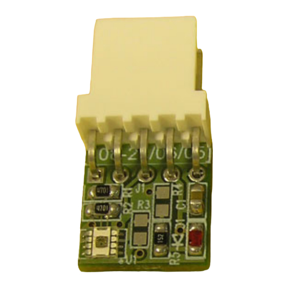
Ambient light sensor demonstration board
●
1 x VM6101 demonstration board
●
Parallel port cable
Demonstration board
Demonstration board
Description
Rev 1
UM0214
User manual
www.st.com
1/9
Advertisement
Table of Contents

Subscribe to Our Youtube Channel
Related Manuals for ST VM6101


Summary of Contents for ST VM6101
- Page 1 UM0214 User manual Ambient light sensor demonstration board Introduction This user manual, along with the VM6101 datasheet will enable you to evaluate the VM6101. Kit contents ● 1 x VM6101 demonstration board ● Parallel port cable Order codes Part number...
-
Page 2: Demonstration Board
Hardware UM0214 Hardware Demonstration board Figure 2. Demonstration board schematic... -
Page 3: Bill Of Materials
UM0214 Hardware Bill of materials Table 1. Demonstration board BOM Reference Description Manufacturer Part number Ambient light sensor STMicroelectronics VM6101V008 Red Led - surface mount Standard component - many suppliers 1uF Ceramic Capacitor Standard component - many suppliers R1,R2 4K7 I2C pullup resistors Standard component - many suppliers 1K5 Resistor Standard component - many suppliers... -
Page 4: Installation
DMA Off Save and Exit Install the v2wreg driver by double clicking on the InstV2W.exe icon and follow the commands given by the installation wizard. Copy across the ‘VM6101_DEMO_release_v*.*.exe’ and the ‘VM6101_ACQ.exe’ applications to a suitable location (for example C:\VM6101). - Page 5 UM0214 Software Connection Connect VM6101 demo board to the parallel port via the cable supplied. Open VM6101_Demo application by double clicking on it. If an initial connection error occurs and the software cannot connect to the hardware the following error message is displayed: Figure 4.
- Page 6 Software UM0214 Figure 5. VM6101 demo app dialog Demo application options Start/stop This button starts/stops the demo, on start the Y bars shows each of the pixel's activity. Exit This button closes down the application. About This button shows the version information.
- Page 7 UM0214 Software Figure 6. PWM option Threshold The Threshold options include upper and lower threshold setting with Greater Than / Less Than tick boxes for these thresholds and Active High / Low O utput . The default is for the Upper Threshold to be set to 19.531 W/m2 with the Less Than box ticked (as shown in Figure 5 ), the output is set to Active High .
-
Page 8: Revision History
Revision history UM0214 Revision history Table 2. Document revision history Date Revision Changes 5-Jun-2006 Initial release. - Page 9 No license, express or implied, by estoppel or otherwise, to any intellectual property rights is granted under this document. If any part of this document refers to any third party products or services it shall not be deemed a license grant by ST for the use of such third party products or services, or any intellectual property contained therein or considered as a warranty covering the use in any manner whatsoever of such third party products or services or any intellectual property contained therein.
Need help?
Do you have a question about the VM6101 and is the answer not in the manual?
Questions and answers