Table of Contents
Advertisement
Quick Links
UM3151
User manual
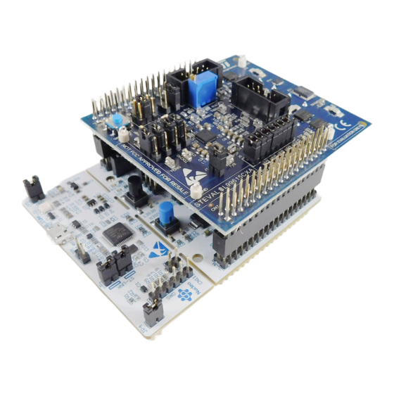
Getting started with the STEVAL-L99615C evaluation kit based on the L9961
device for battery management system
Introduction
The
STEVAL-L99615C
is an evaluation kit composed of an expansion board containing the L9961 IC for battery pack monitoring
solutions, and the
NUCLEO-G071RB
STM32 Nucleo-64 development board, aiming to demonstrate the performance and the
ease of integration with STMicroelectronics technology for BMS applications.
The kit exploits the characteristics of the L9961, able to monitor up to five Li-Ion battery cells in series configuration,
communicating with the
STM32G071RB
microcontroller, through the I²C interface.
The expansion board has been specifically developed to be stacked on the
NUCLEO-G071RB
development board through the
ST morpho connectors, and embeds a power connector able to connect it to a 5-cell battery pack, or alternatively to an external
power supply to emulate the battery pack.
A software package containing a dedicated firmware program for the
STM32G071RB
microcontroller and a GUI for the PC, has
been released to permit users to benefit from the demonstration, looking at the major significant characteristics described by
BMS application: cell voltage and stack voltage monitoring, stack current monitoring, temperature conversion via external NTC,
OV, and UV thresholds management, etc..
Figure 1.
STEVAL-L99615C evaluation kit
UM3151 - Rev 1 - April 2023
www.st.com
For further information contact your local STMicroelectronics sales office.
Advertisement
Table of Contents

Subscribe to Our Youtube Channel
Related Manuals for ST STEVAL-L99615C


Summary of Contents for ST STEVAL-L99615C
-
Page 1: Figure 1. Steval-L99615C Evaluation Kit
NUCLEO-G071RB development board through the ST morpho connectors, and embeds a power connector able to connect it to a 5-cell battery pack, or alternatively to an external power supply to emulate the battery pack. A software package containing a dedicated firmware program for the... -
Page 2: Getting Started
M0+ 32-bit RISC core operating at up to 64 MHz frequency, with 128 KB flash memory and 16 KB SRAM. The ST morpho headers allow expanding the functionality of the STM32 Nucleo open development platform with a wide choice of specific shields. -
Page 3: Expansion Board
It also features protection against overcurrent (both directions) and short-circuit in discharge events. Safety relevant configurations can be stored in the internal NVM to avoid reprogramming the device at each wake-up. Figure 3. STEVAL-L99615C expansion board - top and bottom UM3151 - Rev 1 page 3/30... -
Page 4: Power Supply Section
UM3151 System architecture 1.2.3 Power supply section In case a real battery is not available, it is possible to use the battery simulator embedded on the L9961 demo board by installing a J5 jumper and by feeding the L9961 demo board through the CN2 connector (B+ and B-). Figure 4. -
Page 5: Pack Relays Stage
UM3151 System architecture 1.2.4 Pack relays stage The L9961 uses a dual pre-driver stage to manage the external Charge (CHG) and Discharge (DCHG) switches. The pre-driver stage can be configured as high-side or low-side by programming the CHG_HS_LS and DCHG_HS_LS field. To set the DCHG MOSFET to high-side operation, remove the J13 and J14 jumpers and install a jumper in J15 and J16 position 1-2 or for low-side operation, remove the J19 and J20 jumpers and install a jumper in position 2-3. -
Page 6: Fuse Stage
UM3151 System architecture 1.2.5 Fuse stage Under certain conditions classified as permanent failures, the L9961 can be programmed to activate the FUSE pre-driver. An external NMOS can be driven to blow up a fuse connected in series to the battery pack positive terminal. -
Page 7: L9961 Demo Board Connectors
UM3151 System architecture 1.2.6 L9961 demo board connectors The CN1 is a 10-pin IDC style connector used to route sense signals from the remote 5-cell battery board to the L9961 demo board. The connector contains the Kelvin connections for C0 through C5, the current sense resistors differential voltage, and the NTC voltage, which can be used to route an external NTC and shunt resistor. -
Page 8: Jumpers And Connectors
Host Adapter or a Beagle I C/SPI Protocol Analyzer CN7, ST morpho connector: used to place L9961 demo CN10 board on top of the NUCLEO-G071RB micro board Used to measure current flowing into VB pin 1-2: 3.3 V from micro VIO voltage selector 2-3: 3.3 V from L9961 (VREG) -
Page 9: Nucleo-G071Rb Micro Board Jumpers And Connectors
Description Configuration Type STLINK USB connector USB micro-B ST morpho connector: used to pace L9961 demo CN7, CN10 board on top of the NUCLEO-G071RB micro board OPEN: no 5 V power 1-2 CLOSED: 5 V from STLINK 5 V jumper selection... -
Page 10: Application Setup
USB Type-A to Micro-B cable • a portable power supply (up to 20 V, 1 A) to feed the STEVAL-L99615C kit (in case a real battery is not available), possibly equipped with a two or four position plug 7.62MM connector as the Wurth... -
Page 11: How To Run The Application Demo
To run the application demo, in voltage and NTC temperature acquisition mode, follow the procedure below: Step 1. Verify that the setting of the STEVAL-L99615C jumpers respects the configuration reported in Table Figure 10. STEVAL-L99615C jumpers setting Table 4. Jumper settings Name Board Description Configuration Used to measure current flowing into VB EXP. -
Page 12: Figure 11. How To Connect The Power Terminals To The Battery
UM3151 How to run the application demo Step 3. Connect the power supply terminals to the B+ and B- pins of the battery pack connector (CN2), and power on the appliance (suggested setting 7.5 V, 1 A as test rating). Figure 11. -
Page 13: Figure 12. Gui View And Focus On Connected Com
UM3151 How to run the application demo Step 4. Launch the GUI on the laptop and verify the COM used by the evaluation board is recognized by laptop Operative System (WINDOWS in the described case) device manager. If recognized, the GUI releases a message on the left part of the bottom side of its template, referring to the connected COM number used. -
Page 14: Figure 13. Steval-L99615C Connected To A Laptop (Panoramic View)
UM3151 How to run the application demo Figure 13. STEVAL-L99615C connected to a laptop (panoramic view) UM3151 - Rev 1 page 14/30... -
Page 15: Figure 14. Gui Tab "Register Load'' - Open
UM3151 How to run the application demo Step 5. Clicking on the GUI tab "Register Load", upload the example CSV file "Voltage Acquistion Init - 5Cell+VB+NTC.csv" also embedded in the SW package file, and then click the "Play" button. This operation presets an instruction set that permits the GUI to demonstrate the acquisitions of voltage cells and battery pack, and also NTC acquisition. -
Page 16: Figure 16. Register Load: Csv Commands Loaded
7.5 V to the CN2 connector (on VB+ and VB+ pins), the five resistive dividers integrated in the STEVAL-L99615C expansion board and emulating the battery pack circuit, return 1.5 V for each cell. -
Page 17: Board Schematics
The schematic diagrams below refer to the expansion board included in the STEVAL-L99615C evaluation kit. For the schematic diagrams of the NUCLEO-G071RB development board, see the related page. Figure 18. STEVAL-L99615C expansion board schematic (1/5) U_L9961 U_Connectors L9961.SchDoc Connectors.SchDoc GPIO GPIO Charge... -
Page 18: Figure 19. Steval-L99615C Expansion Board Schematic (2/5)
UM3151 Board schematics Figure 19. STEVAL-L99615C expansion board schematic (2/5) VREG 4.7K 4.7K BATT_PACK 10uF 220nF 470nF 470nF 470nF 33kR 68nF BATT_PACK 470nF 470nF U_Charge Discharge Charge Discharge.SchDoc TM_ENTER BATT_PACK Charge Charge TNSHIP TISENSEN FUSE ISENSE_N 4.7uF ISENSEN CHG_DCHG TNTC... -
Page 19: Figure 21. Steval-L99615C Expansion Board Schematic (4/5)
UM3151 Board schematics Figure 21. STEVAL-L99615C expansion board schematic (4/5) BATT_PACK BATT_PACK BATT_PACK ISENSEN ISENSEP ISENSEP ISENSEN 10-Pin Male NC/+5V MISO NC/+5V SCLK/MDC MOSI/MDIO AARDVARK 10-Pin Male Charge Charge FAULTN_SAFE GPIO FAULTN WAKEUP CN10 NSHIP NSHIP GPIO VREG AVDD 5VUSB... -
Page 20: Bill Of Materials
UM3151 Bill of materials Bill of materials Note: The BOM below refers to the expansion board included in the STEVAL-L99615C evaluation kit. For the BOM of NUCLEO-G071RB development board, see the related page. Table 5. Expansion board bill of materials... - Page 21 UM3151 Bill of materials Item Quantity Reference Value Description Manufacturer Order code J13, J14, J19, MICRO-MINI 6.9MM Keystone 5102 5102 SMT JMPR Electronics CONN HEADER VERT J1, J4 TSW-102-07-F-S Samtec Inc. TSW-102-07-F-S 2POS 2.54MM J2, J15, J16, CONN HEADER VERT TSW-103-07-G-S Samtec Inc.
- Page 22 UM3151 Bill of materials Item Quantity Reference Value Description Manufacturer Order code TWAKEUP, Jumper Jumper RSPRO 251-8682 PCB 2 LAYER - size PCB 2 LAYER PCB not 77.64x70.52x1.6mm FR4 TG reference thickness copper 70 130-140C° microns UM3151 - Rev 1 page 22/30...
-
Page 23: Kit Versions
STEVAL$L99615CA schematic diagrams STEVAL$L99615CA bill of materials 1. This code identifies the STEVAL-L99615C evaluation kit first version. The kit consists of a STEVAL-L99615CX whose version is identified by the code STEVAL$L99615CXA and a NUCLEO-G071RB whose version is identified by the code NUG071RB$AU2. -
Page 24: Battery Holder
The current chapter contains a reference schematic and relative BOM for developing a 5-cell battery holder. This board, once developed, may be connected to the STEVAL-L99615C kit through the 5-cell battery board connector (CN2), permitting to demonstrate the direct acquisition of the electrical characteristics from the single connected batteries. -
Page 25: Regulatory Compliance Information
UM3151 Regulatory compliance information Regulatory compliance information Notice for US Federal Communication Commission (FCC) For evaluation only; not FCC approved for resale. FCC NOTICE - This kit is designed to allow: (1) Product developers to evaluate electronic components, circuitry, or software associated with the kit to determine whether to incorporate such items in a finished product and (2) Software developers to write software applications for use with the end product. -
Page 26: Revision History
UM3151 Revision history Table 8. Document revision history Date Revision Changes 12-Apr-2023 Initial release. UM3151 - Rev 1 page 26/30... -
Page 27: Table Of Contents
UM3151 Contents Contents Getting started ..............2 Overview . -
Page 28: List Of Tables
STEVAL-L99615C versions ........ -
Page 29: List Of Figures
STEVAL-L99615C connected to a laptop (panoramic view) ........ - Page 30 ST’s terms and conditions of sale in place at the time of order acknowledgment. Purchasers are solely responsible for the choice, selection, and use of ST products and ST assumes no liability for application assistance or the design of purchasers’...
Need help?
Do you have a question about the STEVAL-L99615C and is the answer not in the manual?
Questions and answers