
Related Manuals for Kett L-500


Summary of Contents for Kett L-500
- Page 1 Coating Thickness Tester L-500 Operating Manual Thank you for purchasing this product. Please read the operating manual carefully and use this product properly.
- Page 2 For safety precautions Improper use of the Coating Thickness Tester in violation of the following safety notes may result in death, injury or damage to property due to fire, etc. While the safety of the product has been given considerable attention, read the precautions in the operating manual and use the instrument properly.
-
Page 3: Table Of Contents
CONTENTS 1. Measuring Principles and Features ..........4 ■ Measuring principle ................. 4 ■ Features ..................4 2. Specifications ..................5 3. Part names ..................6 ■ Parts of main unit ................6 ■ Accessories ..................7 ■ Description of display and operation keys ........8 4. -
Page 4: Measuring Principles And Features
1. Measuring Principles and Features The Coating Thickness Tester L-500 is a coating thickness gauge that can measure in both electromagnetic type and eddy current type depending on the probe to be connected. ■ Measuring principle ● Electromagnetic type (Fe probe) ● Eddy current type (NFe probe) M e a s u r e m e n t o f n o n - m a g n e t i c c o a t i n g s o n... -
Page 5: Specifications
2. Specifications ● Main unit specifications Display resolution : 0.1μm (when less than 100μm), 1μm (when 100μm or more) Display : Digital (backlit LCD) Data memory : 24,000 points Number of application : 50 (per probe) memories External output : USB serial Power supply : 100-240V AC (50/60Hz) or battery 1.5V (AA alkaline) ×8 (main unit ×4, printer ×4) Power consumption : 25W... -
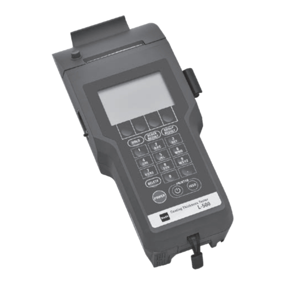
Page 6: Part Names
3. Part names ■ Parts of main unit <Front> Printer paper cutter Open/close button Printer paper cover Probe holder Display Operation keys <Rear> <Side> Data output terminal (USB Mini-B) AC adapter socket Probe connector Bat ter y compar tment for printer Cable holder Battery compartment Strap holder for main unit... -
Page 7: Accessories
■ Accessories Iron substrate Aluminum substrate Calibration foils ×6 1.5 V batteries (AA alkaline) ×8 AC adapter For Fe probe For NFe probe Power cable, POC00 Probe adapter Strap Printer paper ×2 Protective sheets ×3 At the time of shipment, one roll is set in the main unit. -
Page 8: Description Of Display And Operation Keys
■ Description of display and operation keys Date and time (→P.36) 2 0 2 1 / 0 1 / 1 5 1 4 : 2 6 N=05535 Data number Application number (→P.20) Group number (→P.28) APP 01 T E S T- 1 GRP 01 Block number (→P.27) Average in current block B=001 Bn=05535... -
Page 9: Measurement Preparation
4. Measurement Preparation (1) Power supply preparation This unit can be used with 100-240 VAC (50/60Hz) or batteries. Use the supplied power cord POC00 for a 100 VAC power supply. ● When 100-240 VAC is used Connect the supplied power cord and AC adapter, and insert the plug of the AC adapter into the AC adapter socket on the side of the main unit. - Page 10 (2) Probe selection There are two types of probes: electromagnetic type (Fe probe) and eddy current type (NFe probe). Select the probe according to the material of the substrate to be measured. ● Electromagnetic (Fe probe) cable is black →For measuring non-magnetic coating on magnetic metals ● Eddy current (NFe probe) cable is gray →For measuring insulating coating on non-magnetic metals (3) Probe attaching/detaching...
-
Page 11: Measurement Mode
5. Measurement Mode Procedure Display 1. Turn on the power switch. Press the [POWER] key of the main unit. 2. Perform foil calibration and substrate calibration. For an object to be measured for the first time, perform foil calibration and substrate calibration, and register the application (→P.20). -
Page 12: About Statistics Function
6. About Statistics Function The product is equipped with the statistics function that calculates average values and so on. ● Statistical contents Calculates average values, standard deviations, maximum values, and minimum values. ● Preparation for statistics Measured data must be stored in memory for statistics. Set "Data memory"... - Page 13 ● Screen information about statistics <When the screen displays all items> 2 0 2 1 / 0 1 / 1 5 1 4 : 2 6 N=05535 Data number Group number APP 01 T E S T- 1 GRP 01 Average value of blocks Block number B=001 Bn=05535...
-
Page 14: Various Settings
7. Various settings When the [SET] key is pressed on the measurement screen, the following menu screen will be displayed. For each function and operation method, refer to the reference page described as (P. ○○). * Once each function is set, the setting content will be kept intact even after the power is turned off until it is changed. - Page 15 1 Substrate calibration At the time of measurement, even if the type of coating is the same, the measurement value may be affected by the material and shape of the substrate (the same as the one to be measured, with no coating such as plating or painting on the surface). Perform a substrate calibration to correct the effect of the substrate before measurement. Once the substrate calibration is registered, it will be stored in the application (→P.20).
- Page 16 2 Foil calibration Foil calibration is always required before measurement to obtain correct measurement values with the coating thickness tester. First, prepare a "substrate" that has the same material, shape and thickness as the object to be measured, and to which no coating such as plating or painting is applied.
- Page 17 ● When the measurement method is electromagnetic and the substrate and 4 calibration foils (100/300/500/700μm) are used for calibration For the foil calibration method, also refer to the "Easy Adjustment Guide" included with this unit. Operating procedure Display Precautions 1. Check the application number. 2 0 2 1 / 0 1 / 1 5 1 4 : 2 6 N=05535 Before making calibrations, check APP 01...
- Page 18 Operating procedure Display Precautions 6. Perform measurement of substrate. * P r e p a r e a n d u s e a s u b s t r a t e Cal. APP 01 TEST-1 a c c o r d i n g t o t h e o b j e c t t o b e Measure a substrate without any Substrate measurement M e a s u r e s u b s t r a t e .
- Page 19 Operating procedure Display Precautions 8. Measure the calibration foil (2nd foil). * If you want to finish the calibration Cal. APP 01 TEST-1 with 1 or up to 3 calibration foils, Place the calibration foil (300μm) on F o i l c a l i b r a t i o n M e a s u r e 2 n d f o i l .
- Page 20 3 Application The probe can store 50 different applications. Calibration result, application name (up to 12 alphanumeric characters) and the upper and lower limits (→ P.22) can be saved in each application. Operating procedure Display Precautions 1. P r e s s t h e [ S E T ] k e y o n t h e * Select [App] on the function key on the measurement screen to move to measurement screen (→P.14).
- Page 21 Operating procedure Display Precautions <When selecting "App list"> * By pressing the [DELETE] key during >> APP 01 TEST-1 selection of application number, you Select any application number with APP 02 APP 03 can delete the saved name, calibration the [▲] and [▼] keys, and then APP 04 result and the upper and lower limits.
- Page 22 4 Upper and lower limits It is a function to set the upper limit or lower limit and notify on the screen with a buzzer sound when a measurement value exceeds it. * The screen display will be displayed on the left side of the measurement value and the upper limit will be displayed with "▲" and the lower limit with "▼". When printed, "!" will be displayed on the right side of the measurement value.
- Page 23 5 Unit You can set the display unit (μm, mils) of measurement value. * Saved measurement data will also be displayed in the selected unit. Operating procedure Display Precautions 1. P r e s s t h e [ S E T ] k e y o n t h e measurement screen (→P.14).
- Page 24 6 Measurement Mode Either of "Hold mode" that fixedly displays a measurement value and "Continuous mode" that displays measurement value by continuous monitoring can be set. * The measurement mode at the time of calibration is fixed to "Hold mode". * In "Continuous mode", press the tip of the probe against the measurement point and press the [HOLD] key when the measurement value is stabilized.
- Page 25 Statistics You can display the average value, standard deviation, maximum value and minimum value and also can set data range to be calculated. "Group statistics", "Block statistics" and "Data statistics" can be selected for data range to be calculated. * When performing statistical calculations, set “Data memory” to "Enable" before starting a measurement (→ P.31).
- Page 26 Operating procedure Display Precautions 4. Select an item to display. ○S t a t i s t i c s Select an item to display with the [▲] ◀ >> G r o u p s t a t i s t i c s and [▼] keys, and then press the B l o c k s t a t i s t i c s D a t a # s t a t i s t i c s...
- Page 27 8 Block update You can create a block that summarizes the measurement data. When the block number is updated, a new number will be assigned and the old number will become unavailable. You c an create up to 255 blocks. If you have used up to 255, delete all the measurement data and block data (→P.30).
- Page 28 9 Group function You can set groups to which each block belongs. By setting groups, statistical calculation can be performed across multiple blocks. Groups are numbered 1 through 50 and different names can be saved for each number. Operating procedure Display Precautions 1.
- Page 29 Operating procedure Display Precautions <When selecting "App list"> >> GRP 01 TEST-1 Select a desired group number GRP 02 GRP 03 with the [▲] and [▼] keys, and then GRP 04 GRP 05 press the [ENTER] key. GRP 06 GRP 07 GRP 08 ▲...
- Page 30 0 Delete data You can delete measurement data. * The measurement data obtained most recently can be deleted by pressing the [DELETE] key. * Any deleted data will not be included in the statistical calculation results (→P.25). Operating procedure Display Precautions 1. P r e s s t h e [ S E T ] k e y o n t h e * Pr e s s a n d h o l d t h e [5] key o n t h e measurement screen to move to <When measurement screen (→P.14).
- Page 31 ! Data memory You can set whether to save measurement data in the data memory. Operating procedure Display Precautions 1. P r e s s t h e [ S E T ] k e y o n t h e measurement screen (→P.14).
- Page 32 @ Data output You can output measurement data to a PC. Please check the required specifications to connect with a PC (→P.40). Operating procedure Display Precautions 1. P r e s s t h e [ S E T ] k e y o n t h e measurement screen (→P.14).
- Page 33 # Auto power off You can set the time to automatically turn off the power when no measurement or key operation is performed for a certain period of time. Operating procedure Display Precautions 1. P r e s s t h e [ S E T ] k e y o n t h e measurement screen (→P.14).
- Page 34 $ Backlight You can set the brightness and the lighting time of the backlight. This is a convenient function to set when measuring in a dark place or when no operation is performed for a certain period of time. * The brighter the backlight or the longer the lighting time, the greater the decrease in battery life.
- Page 35 % Change print density You can set the print density for output from the printer. * Increasing the print density will greatly reduce the battery life. * As the printer head wears out, the print density will become lighter. If the print density is thinner even when this setting is set to the maximum, contact your dealer or us.
- Page 36 ^ Date and time setting You can set the time and date. * When a non-existent day such as February 30th or April 31st is entered, it will be set as the first day of the following month. Example) February 30 → March 1, April 31 → May 1 Operating procedure Display Precautions 1. P r e s s t h e [ S E T ] k e y o n t h e * When the [1] key on the measurement screen is pressed and held as a short- measurement screen (→P.14).
- Page 37 & Display setting The display of the measurement screen can be selected from "All items" or "Simple". In the simple display, the date and time, measurement mode, unit, printer icon, and battery icon are displayed. Operating procedure Display Precautions 1. P r e s s t h e [ S E T ] k e y o n t h e measurement screen (→P.14).
- Page 38 * Software version You can check information including the model, software version, serial number of the main unit and serial number of the probe. Operating procedure Display Precautions 1. P r e s s t h e [ S E T ] k e y o n t h e measurement screen (→P.14).
-
Page 39: Battery/Printer Paper Replacement
8. Battery/printer paper replacement If the following icon is displayed, check by following the respective procedures. Name Icon Description Battery icon The battery for the main unit is exhausted (⇒ P.39 "■ Battery replacement"). Displays the power status of the printer. When the icon is displayed, check the following. •... -
Page 40: Data Output
9. Data output By connecting to a PC, this unit can output data such as measurement values and statistical calculation results. You can also use a USB port as a serial COM port by installing the driver before connecting. Please download and use the latest FTDI "Virtual COM port (VCP) driver". - Page 41 Example) Group statistical calculation result 10 11 12 13 14 15 16 17 18 19 20 21 22 23 24 25 26 27 28 Output data Character -----GROUP RESULT----- ASCII code 2D 2D 2D 2D 2D 47 52 4F 55 50 20 52 45 53 55 4C 54 2D 2D 2D 2D 2D 0A Character GROUP 50 GROUPNAME ASCII code...
-
Page 42: Handling Precautions
10. Handling precautions ■ Storage After use, clean it well, avoid direct sunlight and store it in a dry place. When not using for a long period of time, remove the power cord and the batteries. It is recommended to store it in a carrying case. ■ Notes regarding measurement (1) Handle the probe carefully so as not to damage it. -
Page 43: If You Thought It Was A Malfunction
11. If you thought it was a malfunction If any of the following symptom is observed, follow the respective procedures to check and take appropriate action. If the symptom cannot be solved even by following the procedures, contact your dealer or us. Symptoms Points to be checked Check/Remedy... -
Page 44: Error Display
12. Error display If any of the following error messages are displayed, follow the procedures described below to check for the cause of the error and take appropriate action to remove the error. If the symptom cannot be solved even by following the procedures, contact your dealer or us. - Page 48 ● We cannot be held responsible for any actions or effects resulting from the execution of any opera- tions outlined in this user manual. 1-8-1 Minami-Magome, Ota-ku, Tokyo 143-8507, JAPAN +81-3-3776-1121 +81-3-3776-3001 https://www.kett.co.jp/english/ overseas@kett.co.jp 060379...
Need help?
Do you have a question about the L-500 and is the answer not in the manual?
Questions and answers