Advertisement
Table of Contents
- 1 Table of Contents
- 2 Measuring Principles and Characteristics
- 3 Instrument View
- 4 Display
- 5 Keypad Fanctions
- 6 Specifications
- 7 Preparations for Operation
- 8 Measuring Procedure
- 9 Functions
- 10 Easy Calibration (for Eddy Current Method Only)
- 11 Notes for Measuring and Handling
- 12 Data Output Format
- Download this manual
Advertisement
Table of Contents

Related Manuals for Kett LE-330J


Summary of Contents for Kett LE-330J
- Page 1 330J Series Coating Thickness Testers LE-330J/LH-330J/LZ-330J Operating Manual...
- Page 2 Coating Thickness Tester Safety Precautions • Be sure to carefully follow all safety precautions. Carefully read operating manual. • Do not use the unit if it is not functioning property. Immediately contact our service representative if the unit malfunctions or does not operate properly. •...
-
Page 3: Table Of Contents
Contents 1. Measuring Principles and Characteristics ................4 2. Instrument view ........................6 3. Display ..........................8 4. Keypad Fanctions ........................ 9 5. Specifications ........................12 6. Preparations for Operation ....................13 7. Measuring Procedure ......................22 8. Functions ..........................24 9. -
Page 4: Measuring Principles And Characteristics
1. Measuring Principles and Characteristics • The model LE-330J electromagnetic coating thickness tester is designed to measure the thickness of non-magnetic coat- ings such as paint or plating on magnetic metal substrates (iron or steel). • The model LH-330J Eddy Current coating thickness tester is designed to measure the thickness of insulating coatings such as alumite or paint on non-magnetic metal substrates (such as aluminum or copper, etc.). - Page 5 • LE-330J • LH-330J (Electromagnetic measurement method : For measur- (Eddy Current measurement method: For measuring ing the thickness of non-magnetic coatings on mag- the thickness of insulating coatings on non-magnetic netic metal substrates) metal substrates) When an alternating current electromagnet is brought near...
-
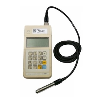
Page 6: Instrument View
2. Instrument view Main part Probe Connector Probe Connector Dust Cap printer & Computer Out put Connector Top View Measurement Part Fe Probe (Black) Electromagnetic (LEP-J) Display Connector Keyboard Battery Box Measurement Part Front Panel Rear Panel NFe Probe (Gray) Eddy Current (LHP-J) - Page 7 Accessories Standard Calibration Foils Probe Adaptor Iron Substrate (FE-J) Aluminum Substrate (NFE-J) (For LE-330J,LZ-330J) (For LH-330J,LZ-330J) (LE-330J,LZ-330J : 6pcs / LH-330J : 5pcs) Carrying Case Batteries size AA (4pcs) Calibration Foilcase Optional Accessories Operating Manual printer VZ-330...
-
Page 8: Display
3. Display Measurement Number Symbol Date ( P. 24) or measurement number Foil Calibrations ( P. 17) Battery Check ( P. 34) Lot Number ( P. 24) Data ( P. 24) Upper Limit ( P. 25) Electromagnetic ( P. 6,13) Eddy Current ( P. -
Page 9: Keypad Fanctions
4. Keypad Fanctions Name Function ON key, OFF key This key is a power supply switch. 1. Number keys 1. This key is used for a number input. 2. Dual-function keys 2. These keys have two functions. 1. This key is used to correct mistakes made when inputting 1. - Page 10 Dual-function Keys : The following keys also have a thing with two functions. These are called function mode key. These keys are pressed immediately after presetting a function key. A result -- as a function mode key -- functioning. Function mode Numeric key Name Function...
- Page 11 Name Function SUBSTRATE CALIBRATION key Substrate ‘0’ calibration. ( press FOIL CALIBRATION key For making foil calibrations. ( press 1. Hold measurement (for auto result entry) CONTINUOUS key 2. Continuous measurement (requires key for result entry) (Each press of this key switches the mode.)( press LIMIT SET key For presetting the upper and lower limits.
-
Page 12: Specifications
* The accessory plastic calibration foils supplied have had their actual values measured. For this reason the values indicated above are only approximate and are not exactlythe same actual thicknesses of the supplied foils. * Standard Accessories Plastic Calibration Foils LE-330J, LZ-330J : Approx. 10,50,100,350,800,1000 (µm) LH-330J : Approx. 10,50,100,350,800, (µm) -
Page 13: Preparations For Operation
2. Selecting and Connecting the probe (LZ-330J) Select a probe appropriate to the type of sample to be measured with switching the main unit off. Slide to open (LE-330J • LZ-330J) Non-magnetic coating on magnetic metal substrates: Connecting the probe Electromagnetic type probe Fe probe (Black)<LEP-J>... - Page 14 3. Adjustment preparation 4. Using the probe Adjustments must be made attempting to make The probe features a 1-point contact, fixed pressure design which ensures fixed load applied the chip on the tip the measurements. However, measurement calibrations are probe. As shown in the diagram, grip the probe near the stored in the unit’s computer memory, therefore new tip and press it against the measurement surface so that adjustments are not required if the sample to be measured...
- Page 15 The LZ-330J has the capacity to store up to a maximum of 4 calibration settings for both electromagnetic and eddy current measurement modes, and the LE-330J has the capacity to store up calibration settings for 4 electromagnetic mode and LH-330J also has the capacity to store up calibration setting for 4 eddy current mode.
- Page 16 2) Substrate Calibration Procedure Once substrate calibration settings have been registered it is not necessary to perform this operation each time a measurement is made. However this procedure must be performed again when changes such as replacement of the probe are made. •...
- Page 17 3) Standard Foil Calibration Procedure Turn on the probe and the main unit and hold the tip of the probe toward the air for 2 ~ 3 seconds. • Example: Performing calibration using the zero foil and standard foils (40, 100 and 400µm foils). Step Operation Display...
- Page 18 Step Operation Display Explanation Press the key while holding the probe toward the air. "---" is shown in the display. Input the coating thickness of the substrate (0.0µm). Press the key. The number displayed disappears and S. NO increments from 0 to 1 to indicate that the unit is entering the standard foil calibration mode.
- Page 19 Step Operation Display Explanation Press the key while holding the probe toward the air. "---" is shown in the display. Input the coating thickness of the calibration foil (40.0µm). Press the key. The number displayed disappears and S. NO increments from 1 to 2 to indicate that the unit is ready for calibration using the second standard foil.
- Page 20 Step Operation Display Explanation Press the key while holding the probe toward the air. "---" is shown in the display. Input the coating thickness of the calibraiton foil (100.0µm). & Press the key. The number displayed disappears and S. NO increments from 2 to 3 to indicate that the unit is ready for calibration using the third standard foil.
- Page 21 Step Operation Display Explanation Press the key while holding the probe toward the air. "--- " is shown in the display. Input the coating thickness of the calibraiton foil (400.0µm). Press the key. The display returns to its original state. This completes the calibration procedure.
-
Page 22: Measuring Procedure
7. Measuring Procedure (1)Select & Connect the probe (4) Delete contents of the measurement (6) Specify calibration settings value memory In the LZ-330J, select the appropriate type of Specify the calibration memory address of cali- probe for the type of material to be measured. bration settings registered for the type of material Except in cases in which you wish to continue P. - Page 23 (7) Enter comments such as the date and lot number, etc. (9) Data Processing (Statistical Processing) Commentary information which can be entered includes the date, lot num- • Example: Lot Statistical Calculations ber, and upper and lower measurement value limits. This information is AV: Average value SD: Standard deviation MAX: Maximum value MIN: Minimum value input as necessary.
-
Page 24: Functions
8. Functions (1) Entering the Date (2) Entering the Lot Number • • Example: Entering the date as May 6, 2003 Example: ntering 651 as the lot number Step Operation Display Step Operation Display • Up to three digits can be input for the lot number. •... - Page 25 (3) Setting Limit Values • Upper and lower limits are set when it is necessary to check that coating thickness values are within a certain range. • • A buzzer sounds and the " " indicator appears in the display if Example: Setting the upper limit at 100µm and the lower limit at 50µm.
- Page 26 (4) AC (All Clear: delete the contents of measurement value memory) (5) DEL (Partial deletion of measurement value data) This operation deletes the measurement data, statistical results and com- You can delete specific measurement values such as erroneous ments from the unit's memory. measurement data which you do not wish to be used in statistical calculations.
- Page 27 (6) CONT (Changing the Measurement Value Display Mode) • The Continuance Mode is used in cases such as the measurement of coatings on complexly shaped objects in which measurement values have a tendency to be unstable. This allows you to obtain You can switch the measurement value display mode between the Hold stable measurement values and makes statistical processing easier (fixed value display) and Continuance (continuous monitoring) modes.
- Page 28 • (7) LOT RES (Lot statistical calculations) Example: Measurement data for the lot is 162µm x 2 and 163µm x 2 and a printer is not connected. Step Operation Display The 330J series are capable of providing statistical results by lot. However, lot statistics can not be obtained without at least 2 sets of mea- surement data for a particular lot.
- Page 29 (8) RESULT (Overall statistical results) 1. When not using a printer • Example: Setting to lot 1 and making 3 measurements (X ), and then setting to lot 2 and making 2 measurements (X ). Calculate statistical results based on all of the measurement data thus collected. No printer connected. Y1 in the explanation column represents the average value of measurements X and X represents the average value of measurements X...
- Page 30 Step Operation Display Explanation of Calculated Results Average of Y and Y Standard deviation of Y and Y Maximum value of Y and Y Minimum value of Y and Y Returns to the measurement display. • You can reconfirm any of the statistical values by pressing the corresponding key indicated above before pressing the key.
- Page 31 2. When connected to a printer (9) DATA TRANS (Data transmission) Step Operation Display You can send measurement data or various statistical data obtained previ- ously (overall or by lot) to the printer all at once. (This data can also be transmitted to a computer in the same way.) Step Operation Display...
-
Page 32: Easy Calibration (For Eddy Current Method Only)
9. Easy Calibration (For Eddy Current method only) Simplified "easy" adjustment can be made in order to make Eddy Current measurement mode measurements. (Easy adjustment is not possible for the electromagnetic measurement mode.) If the coating thickness does not exceed 500µm, measurement results are as precise as those obtained using standard foil calibration adjustments. -
Page 33: Notes For Measuring And Handling
10. Notes for Measuring and Handling (1) Confirm the type of material being measured. Be sure to check the type of material and select the correct probe type before beginning measurements. (2) Do not damage the probe or get it dirty. Accurate measurement results cannot be obtained if the chip on the tip of the probe is damaged or dirty. - Page 34 (4) Replace the batteries immediately if the low-voltage indicator is displayed. When the batteries become weak, a "BAT" indicator will appear in the display when the power is first turned on or while the tester Caution is in use. Immediately replace the batteries with 4 new size AA alkaline batteries when this indicator is displayed. Please note that calibration adjustments are maintained in the unit's non-volatile memory even when the batteries are exhausted.
-
Page 35: Data Output Format
11. Data output format (1) Transmission of data The 330 series may be connected to either an optipnal printer or PC printer to out measurement data or statistical results. <Data communications> Standard RS-232C <Interface Specifications> Digits Output Notes Baud rate : 2400bps 0 1 2 3 4 5 6 7 8 9 10 11 12 13 14 15 16 17 18 19 20 21 22 23 24 Data bits... - Page 36 (2) Example Printout Performing measurements and statistical calculations with a printer connected to the unit and printing out the results thus obtained. Operation Print Out Notes µm Example: The date as May 6, 2003 Statistical calculations for Lot 100. (Measurement) Statistical calculations for Lot 200.
- Page 37 Operation Print Out Notes Overall statistical calculations for measurement data from N = 0001 to N = 0006. Statistical processing of results of statistical calculations for LOT 001 and LOT 002 (AV). Statistical calculations for Lot 300. (Measurement data prior to N = 0006 (Measurement) is not subject to this statistical processing.)
- Page 38 MEMO...
- Page 40 0601•TO•0102•200...
Need help?
Do you have a question about the LE-330J and is the answer not in the manual?
Questions and answers