Advertisement
Table of Contents
- 1 Table of Contents
- 2 Measuring Principles and Characteristics
- 3 Instrument View
- 4 Display and Keypad Functions
- 5 Specifications
- 6 Preparations for Operation
- 7 Operation Method
- 8 Settings
- 9 Calibration
- 10 Battery Replacement
- 11 Data Output Format
- 12 Troubleshooting
- 13 Notes for Measuring and Handling
- Download this manual
Advertisement
Table of Contents

Related Manuals for Kett LH-373


Summary of Contents for Kett LH-373
- Page 1 373 Series Coating Thickness Testers LE-373/LH-373/LZ-373 Operating Manual...
- Page 2 Coating Thickness Tester Safety Precautions ● Be sure to carefully follow all safety precautions. Carefully read operating manual. ● Do not use the unit if it is not functioning property. Immediately contact our service representative if the unit malfunctions or does not operate properly. ●...
-
Page 3: Table Of Contents
Contents 1. Measuring Principles and Characteristics ........4 2. Instrument view ................6 3. Display and Keypad Functions ........... 8 4. Specifications ................9 5. Preparations for Operation ............10 6. Operation Method............... 11 7. Settings ..................12 8. Calibration .................. 24 9. -
Page 4: Measuring Principles And Characteristics
1. Measuring Principles and Characteristics • The model LE-373 electromagnetic coating thickness tester is designed to measure the thickness of non-magnetic coatings such as paint or plating on magnetic metal substrates (iron or steel). • The model LH-373 Eddy Current coating thickness tester is designed to measure the thickness of insulating coatings such as alumite or paint on non-magnetic metal substrates (such as aluminum or copper, etc.). - Page 5 • LE-373 • LH-373 ( Electromagnetic measurement method : For ( E d d y C u r r e n t m e a s u r e m e n t m e t h o d : F o r...
-
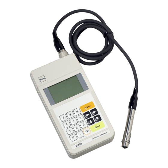
Page 6: Instrument View
2. Instrument view Main part Probe Connector Probe Connector Dust Cap printer & Computer Out put Connector Top View Measurement Part Fe Probe (Black Cable) Electromagnetic “LEP-J” Connector Display Keyboard Battery Box Measurement Part NFe Probe (Gray Cable) Eddy Current “LHP-J” Front Panel Rear Panel... - Page 7 Accessories Iron Substrate (FE-373) Aluminum Substrate (NFE-373) Standard Calibration Foils Probe Adaptor (For LE-373,LZ-373) (For LH-373,LZ-373) (LE-373,LZ-373 : 6pcs / LH-373 : 5pcs) Batteries size AA (4pcs) Carrying Case Operating Manual Calibration Foilcase Optional Accessories Calibration Foils Measuring Stand Printer VZ-380...
-
Page 8: Display And Keypad Functions
3. Display and Keypad Functions Date & Time or Lot & Data numbers Battery alarm (see p. 31) (see p. 19) Measuring method Measurement Value (FE : Electromagnetic or Measurement Units (see p. 21) NFe : Eddy-Current) Calibration (see p. 24) Settings (see p. -
Page 9: Specifications
4. Specifications LZ-373 / Electromagnetic and Eddy-current Model / Measuring Method LE-373 / Electromagnetic LH-373 / Eddy-current Probe Type LEP-J (Fe) LHP-J (NFe) Applications Non-magnetic coatings on magnetic metal (iron, steel) Insulating coatings on non-magnetic metal (non-iron) Measurable Range 0 to 2500μm or 99.0 mils 0 to 1200μm or 47.0 mils... -
Page 10: Preparations For Operation
(2) Selecting and Connecting the probe (LZ-373) Slide to open Select a probe appropriate to the t ype of sample to be measured with switching the main unit off. (LE-373 • LZ-373) Connecting the probe Non-magnetic coating on magnetic metal substrates: Electromagnetic type probe Fe probe (Black)<LEP-J>... -
Page 11: Operation Method
6. Operation Method (1) Probe selection and attachment Probe usage method Probe adapter usage Check that the power supply is off and then attach either method the LEP-J or LHP-J probe according to the substrate to be measured (see p. 10). (2) Power ON Press the Power key. -
Page 12: Settings
7. Setting ● The following 16 functions can be selected on mode. 1 Application (P.14) 0 Brightness (P.20) 2 Substrate Cal. (P.14) ! Lighting Time (P.21) 3 Delete Data (P.15) @ Unit (P.21) 4 Data Memory (P.16) # Data Output (P.22) 5 Limits (P.17) - Page 13 ● Procedure of Various Functions <Display Example> (1) To set various function, select by pressing key. Press key and the various functions will be displayed. (2) Select a function you required by keys,and press key. In case of right diagram, Application function is selected.
- Page 14 1 Application 2 Substrate Cal. LE-373 & LH-373 : A total of 100 applications (calibration Once substrate calibration has been done, it is not curves) can be set. necessar y to per form calibration for subsequent LZ-373 : A total of 100 applications , consisting of measurements.
- Page 15 3 Delete Data The measurement data in Data Memory can be deleted. (1) Perform steps (1) and (2) on p.13. (2) Press the Del key, and after the displayed data number has disappeared, enter the data number to be deleted from the numeric keypad.
- Page 16 4 Data Memory Set whether or not to save the measurement data to the data memory. (1) Perform steps (1) and (2) on p.13. (4) To c a n c e l s a v i n g t o d a t a memory, select Null by pressing...
- Page 17 5 Limits This function memorizes the upper and lower limits and emits a beep to notif y the operator when the measurement value exceeds the set upper limit or falls below the lower limit. (1) Perform steps (1) and (2) on p.13. (4) T o l e a v e t h e s e t t i n g s u n c h a n g e d , s e l e c t E s c...
- Page 18 6 Statistics This function displays the maximum value, minimum value, calibration deviation, and the average value and sets the data range to be calculated. To e x e c u t e S t a t i s t i c s , f i r s t s e t S t o r e p r i o r t o measurement (see p.
- Page 19 7 Disp. Property 8 Date/Time The measurement screen can be selected from [Date/ The Date/Time can be set. Time] and [Lot/Data No.]. (1) Perform steps (1) and (2) on p.13. (1) Perform steps (1) and (2) on p.13. (2) A d j u s t t h e D a t e / T i m e b y pressing the ←...
- Page 20 9 Auto Off Time 0 Brightness The time until the power is automatically switched off The brightness of the backlight can be set (Off, Dark, in the absence of measurement or key operation can be Medium, Lightish), allowing the operator to set the set (5minutes, 10minutes, 20minutes, or Continuous).
- Page 21 ! Lighting Time @ Unit The lighting time for the backlight can be set to 5s, 10s, The display unit (μm, mils) for measurement values can or 20s. be set. * If "Off" has been set for Brightness (see p. 20), this setting need not be done.
- Page 22 # Data Output $ Lot Splitting The measured data can be output to a personal Lot numbers can be automatically incremented as computer or a printer by connecting the optional Statistics are executed. cable or printer. (1) Perform steps (1) and (2) on p.13. (1) Perform steps (1) and (2) on p.13.
- Page 23 % Hold/Continues Two measurement modes are available, "Hold" whereby * In the continues measurement mode, press the enter key the measurement value is displayed statically (fixed when the measurement value has stabilized while placing the probe tip on the measurement sur face. The value value), and "Continues"...
-
Page 24: Calibration
8. Calibration ● Preparations for calibration Calibration prior to measurement is necessary in order To ensure the highest possible measurement precision, to obtain accurate measurement values from the coating a substrate made with the same material, shape, and thickness tester. Once calibration has been performed for thickness as the pieces to be measured, must be used. - Page 25 ● Calibration Procedure First, set an application number for the application (calibration curve), referring to 1 Application on p. 14. The rest of the procedure is described below. * Once set, the application number remains in memory even after the power is switched off. Procedure Example : Calibration with electromagnetic measurement mode , using a substrate and 4 calibrations foils (100, 300, 500, 700 µm).
- Page 26 Step Operation Display Explanation Press the Enter key. The substrate is measured 7 times. Substrate measurement ・ ・ ・ ・ The substrate is measured 7 times. Press the Enter key to return to the initial screen.
- Page 27 Step Operation Display Explanation by pressing the ← or → key. Select * The display shows the previous measurement mode (Fe or NFe). Press the Enter key to switch to the calibration display. Measure an uncoated substrate 4 or 5 times. Each time Substrate measurement a measurement is completed, a beep sounds and the measured value is displayed.
- Page 28 Step Operation Display Explanation Press the Enter key and check that the thickness (0.0 μm) of the substrate coating is displayed. To change the thickness of the substrate coating, delete the value with the Del key, and enter the desired thickness of the substrate numeric keypad coating from the numeric keypad.
- Page 29 Step Operation Display Explanation Press the Enter key. Clear the numeric value with the Del key and enter the thickness (100μm) of the calibration foil from the numeric keypad. numeric keypad Press the Enter key to set the calibration foil (100 μm). The displays changes from Standard 1 to Standard 2.
- Page 30 Step Operation Display Explanation Press the Enter key to return to the initial display. * If is selected on the display during step @ through ^ and the Enter key is pressed, the calibration settings are canceled. * The purpose of performing measurement 4 to 5 times for each calibration using a substrate and calibration foils is to obtain the average value.
-
Page 31: Battery Replacement
9. Battery Replacement ● The Battery Alarm When the battery alarm symbol is displayed, immediate replace to new batteries (1.5V alkaline AA size, 4 pcs.). Refer to p.10 (1) Insert the batteries. -
Page 32: Data Output Format
10. Data output format The 373 series may be connected to either an optipnal printer or PC printer to out measurement data or statistical results. <Data communications> <External Output> RS-232C or USB Printer VZ-380 : RS-232C printer cable VZC-60 Personal Computer : RS-232C cable VZC-53 or <Interface Specifications>... -
Page 33: Troubleshooting
11. Troubleshooting Check Items Verification Action ● Open the battery compartment cover at the rear of the unit and Power supply Are the batteries properly set? check. (See "Insert the batteries" on p.10.) ● If they are exhausted, replace them with four new size AA Are the batteries exhausted? alkaline batteries.(See "Battery Alarm"... -
Page 34: Notes For Measuring And Handling
12. Notes for Measuring and Handling (1) Confirm the type of material being measured. Be sure to check the type of material and select the correct probe type before beginning measurements. (2) Do not damage the probe or get it dirty. Accurate measurement results cannot be obtained if the chip on the tip of the probe is damaged or dirty. - Page 36 1205・MA・0301・400...
Need help?
Do you have a question about the LH-373 and is the answer not in the manual?
Questions and answers