
Related Manuals for Kett LZ-200J


Summary of Contents for Kett LZ-200J
- Page 1 Coating Thickness Testers LE-200J/LH-200J/LZ-200J Operating Manual Thank you for purchasing this product. Please read the operating manual carefully and use this product properly.
- Page 2 For safety precautions Improper use of the Coating Thickness Tester in violation of the following safety notes may result in death, injury or damage to property due to fire, etc. While the safety of the product has been given considerable attention, read the precautions in the operating manual and use the instrument properly.
-
Page 3: Table Of Contents
Contents 1. Measuring Principles and Characteristics ................4 2. Instrument view ........................6 3. Accessories .......................... 7 4. Keypad Fanctions ......................... 8 5. Specifications ........................11 6. Preparations for Operation ....................12 7. Measuring Procedure ......................21 8. Functions ..........................25 9. Master Calibration.........................31 10. -
Page 4: Measuring Principles And Characteristics
1. Measuring Principles and Characteristics • The model LE-200J electromagnetic coating thickness tester is designed to measure the thickness of non-magnetic coatings such as paint or plating on magnetic metal substrates (iron or steel). • The model LH-200J Eddy Current coating thickness tester is designed to measure the thickness of insulating coatings such as alumite or paint on non-magnetic metal substrates (such as aluminum or copper, etc.). - Page 5 • LE-200J • LH-200J (Ele ctromagne tic me asure me nt me thod : For ( E d d y C u r r e n t m e a s u r e m e n t m e t h o d : F o r...
-
Page 6: Instrument View
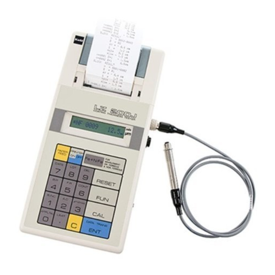
2. Instrument view <Main part> Printer Battery Compartment Printer Paper Compartment Printer Paper Compar tment Cover AC Adapter Socket Printer Paper Cutter Printer Probe Socket LCD Display RS232C Output terminal Keyboard Power Switch Main part Battery Compartment <Side View> <Front Panel> <Rear Panel>... -
Page 7: Accessories
Fe Probe (Black) Electromagnetic (LEP-J) NFe Probe (Gray) Eddy Current (LHP-J) Carrying Case <Accessories> Iron Substrate (FE-J) Aluminum Substrate (NFE-J) Standard Calibration Foils (6pcs) Probe Adaptor AC Adapter (For LE-200J,LZ-200J) (For LH-200J,LZ-200J) Printer Paper Calibration Foilcase Batteries size AA (10pcs) Operating Manual... -
Page 8: Keypad Fanctions
-- functioning. Name Function In order to reduce power consumption, the LE-200J • LH-200J • LZ-200J automatically go into RESET key the Sleep Mode and "SLEEP" will be displayed on the LCD if the unit is left unused for mor than 10 minutes with the power on.The Reset Key is pressed to turn to the measurement mode. - Page 9 This key is used to clear incorrectly numeric data. This key is pressed to use the double-definition key function modes FUNCTION key (date, lot number statistical results, etc.). The LE-200J • LH-200J • LZ-200J features the function modes described below. DATE key This key is used to input (print) the date.
- Page 10 Name Function BLOCK RESULTS key This key is pressed to perform statistical calculations for each block. This key is pressed to obtain statistical results from measurement number FINAL RESULTS key N = 1 to the final measurement number. This key is used to convert the measurement values display between the CONTINUE key Hold Mode and Continuous Monitoring Mode.
-
Page 11: Specifications
5. Specifications LZ-200J Model LE-200J LH-200J Measurement Mothod Electromagnetic Eddy Current Probe Type LEP-J(Fe) LHP-J(NFe) Object of Measurement Non-magnetic coatings on iron and steel substrates Insulating coating on non-magnetic metal substrates Measurement Range 0 ~ 1500µm or 60.00mils 0 ~ 800µm or 32.00mils Measurement Units µm or mils (selectable) -
Page 12: Preparations For Operation
The LE-200J • LH-200J • LZ-200J have been designed for use with either 100V/220V AC 50/60 Hz or dry cell batteries as the power supply. • Running the LE-200J • LH -200J • L Z-200J on a Load baatteries into the main unit 100V/220V AC power supply... - Page 13 2. Loading Battery in the probe Connecting the probe Use the LEP-J (Fe) probe to measure the thickness of non-magnetic coatings on magnetic metal surface or the LHP-J (NFe) probe to measure insulating coatings on non-magnetic metal surface. • The probe can be easily connected to the main unit by turning it a little while softly pressing it into the probe socket on the right side of the main unit.
- Page 14 5. Adjustment preparation 6. Using the probe Adjustments must be made at tempting to make The probe features a 1-point contact, fixed pressure measurements. However, measurement calibrations design which ensures fixed load applied the chip on the tip the probe. As shown in the diagram, grip the probe are stored in the unit’s computer memory, therefore near the tip and press it against the measurement surface new adjustments are not required if the sample to be so that it is perpendicular to the surface. To make the next...
- Page 15 7. Calibrating the LE-200J • LH-200J • LZ-200J 1) The calibration Parameters application number (APPL. No.) is specified. Allowable application The LE-200J • LH-200J • L Z-200J can store up to numbers are from 1 to 4. 4 sets each of calibration parameters for both the electromagnetic and high-frequency measurement • Example : Set the Application Number to 4. Use the LHP-J probe...
- Page 16 2) Performing Calibration • Example: Performing calibration using the zero foil and standard foils (40, 100 and 400µm foils). Step Operation Display Explanation Press the key. * MASTER INF . Press the key while holding the probe toward the air. * ZERO <Calibration using the zero foil> Measure the (substrate) 5 times. The buzzer will sound and (Measure 5 times) * ZERO 0.1 .
- Page 17 <Calibration using the standard foil (40µm)> Step Operation Display Explanation Place the 40µm calibration foil on the substrate and repeat (Measure 5 times) * STD1 40.1. . the measurement procedure 5 times. ・ * STD1 40.5. . ・ ・ ・ •...
- Page 18 <Calibration using the standard foil (100µm)> Step Operation Display Explanation Place the 100µm standard foil on the zero foil (substrate) and (Measure 5 times) * STD2 101 . . repeat the measurement procedure 5 times. ・ * STD2 100 . . ・...
- Page 19 <Calibration using the standard foil (400µm)> Step Operation Display Explanation Place the 400µm standard foil on the substrate and repeat (Measure 5 times) * STD3 401 . . the measurement procedure 5 times. ・ * STD3 400 . . ・ •...
- Page 20 • 5 measurements are made at each stage of the zero and calibration foil adjustment procedure in order to obtain the average measurement value. • If you make errors while entering numeric values during the calibration procedure, press the key to delete the value and then input the correct value.
-
Page 21: Measuring Procedure
7. Measuring Procedure (1) Select & Connect the probe (4) Delete contents of the measurement (6) Specify calibration settings value memory In the LZ-200J, select the appropriate type of Specify the calibration memory address of probe for the type of material to be measured. calibration settings registered for the type of Except in cases in which you wish to continue ( ⇒... - Page 22 (7) Enter comments such as the date and lot number, etc. (9) Data Processing (Statistical Processing) Commentary information which can be entered includes the date, • Example: Lot Statistical Calculations lot number, and upper and lower measurement value limits. This AV: Average value SD: Standard deviation MAX: Maximum value MIN: Minimum value information is input as necessary. ( ⇒ P. 24,25) 1.
- Page 23 (11) Typical Measurement Example Operation Display PrintOut # DATE 03.10.25 =100? =50? # APPL.No=1? # LOT 96321? ・ #FE(NF) 0001 83.7 ・ ・ Measurement ・ # BR N=0001-0005 The block number is increment ➡ # B.INC B=02 ? automatically #FE(NF)
- Page 24 Operation Display PrintOut Measurement #FE 0006 Previous data ➡ # DELETE N=6? is erased. # BR N=0006-0010 # B.INC B=03? # B.INC B=? Block number is set as desired. ➡ # B.INC B=9? ・ ・ #FE 0011 58.3 ・ ・ Measurement #FE 0013 7 .4...
-
Page 25: Functions
8. Functions (1) Entering the Date (2) Entering the Lot Number • Example: Entering the date as October 25, 2003 • Example: ntering 6513 as the lot numbermeasurement. Step Operation Display Step Operation Display # FANCTION KEY # FANCTION KEY # DATE ? # LOT ? # LOT 6513? # DATE 03.10.25 LOT 6513 (Example) This function is used to print out lot numbers (numerical comments). - Page 26 (3) AC (All Clear: delete the contents of measurement value memory) (4) µm/mils (Unit Conversion) This operation deletes the measurement data, statistical results and This function mode is used to switch between µm and mils as the unit of comments from the unit's memory. measurement.
- Page 27 (5) LIMIT (Upper and lower limits) This function mode is used to set upper and lower limits when checking Use the following procedure to erase upper and lower limit setting val- to make sure that measured coating thicknesses fall within a specified ues from memory.
- Page 28 (6) DEL (Partial deletion of measurement value data) (6) B. INC (Block Increment) You can delete specific measurement values such as erroneous The Block Increment function mode is used to move the block number to measurement data which you do not wish to be used in statistical the next or another desired block number and continue measurements calculations.
- Page 29 (7) BR (Block Calculation Results) Press the key to move on to the next operation. This function mode is used to obtain statistical calculation results for each block separately. Please note that there must be measurement # B.INC B=02? data for at least t wo measurements in a block in order to obtain statistical calculation results for that block.
- Page 30 (10) F. R. (Final Result: Overall statistical calculations results) (9) CONT (Continuance) The Final Result function mode is used to obtain the overall statistical Measured values are usually held, but the hold mode can be released calculations results for the measurement data from measurement to perform calibration and measurement when making measurements number N = 0001 to the final measurement made.
-
Page 31: Master Calibration
9. Master Calibration The master calibration operation is performed in the following way when the probe is replaced. * ◯ ◯ ◯ ◯ (4-digit number) 1. Turn the power one while holding down both the keys. * ◯ ◯ ◯ ◯ ◯ (5-digit number) 2. -
Page 32: Notes For Measuring And Handling
10. Notes for Measuring and Handling (1) Confirm the type of material being measured. Be sure to check the type of material and select the correct probe type before beginning measurements. (2) Do not damage the probe or get it dirty. Accurate measurement results cannot be obtained if the chip on the tip of the probe is damaged or dirty. - Page 33 (4) Replace the batteries immediately if the low-voltage indicator is displayed. The following indicators will be displayed on the LCD panel when the main unit or printer section batteries become weak. Please replace the batteries immediately when these indicators appear. 1 % is blinking Both the main unit and printer section batteries are weak.
- Page 36 Caution ● It is strictly prohibited to transfer part or all of this manual without permission. ● The contents of this manual are subject to change without notice. ● The appearances, screens, etc. of the product and accessories displayed on this manual may differ from the actual ones, however, operations and functions are not affected.
Need help?
Do you have a question about the LZ-200J and is the answer not in the manual?
Questions and answers