
Related Manuals for Kett LZ-990


Summary of Contents for Kett LZ-990
- Page 1 Dual Type Coating Thickness Tester LZ-990 Operating Manual Thank you for purchasing this product. Please read the operating manual carefully and use this product properly.
- Page 2 Safety Precautions The Coating Thickness Tester may cause damage to objects being handled if the precautions are not adhered to for safety purposes. The utmost care has been given to the safety of the product, however take care to read the precautions in this operating manual for proper handling. •...
-
Page 3: Table Of Contents
Contents 1. Measuring Principles and Features ........4 2. Specifications ..............6 3. Instrument View ..............7 4. Display Pattern ..............9 5. Keypad Functions ............... 10 6. Battery Installation .............. 11 7. Operation ................12 8. Settings ................14 9. -
Page 4: Measuring Principles And Features
1. Measuring Principles and Features • Electromagnetic method • Eddy Current method (measurement of non-magnetic coatings on (measurement of insulating coating on non- magnetic metals) magnetic metals) If an AC electromagnet is brought into the proximity If a coil with a uniform high-frequency electric current of iron (magnetic metal), the level of the magnetic flux flowing through it is brought into the proximity of metal flow through the coil changes resulting in changes... - Page 5 • Other Functions Automatic ON/OFF switch function. 15 different adjustable settings including upper and lower limits and statistic calculations. Applications Model LZ-990 Paint Plastic Paint Lacquer Resin Alumite (Anodic oxide coating)
-
Page 6: Specifications
2. Specifications Model LZ-990 Measuring Method Electromagnetic and eddy current method (by automatic or manual changing) Applications Non-magnetic coatings on magnetic metal or insulating coatings on non-magnetic metal Measurable Range 0~2000 µm or 0~80.0 mils Measuring Accuracy ±1µm under 50 µm ±2% at 50 µm – under 1000 µm, ±3% at 1000 µm – under 2000 µm Resolution ±0.1 µm under 100 µm... -
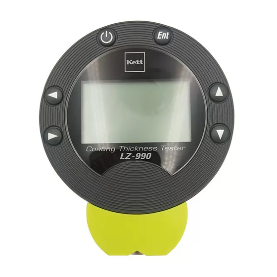
Page 7: Instrument View
3. Instrument View Front Panel Rear Panel Wrist Strap Hole Power Switch Enter Key Buzzer Battery Up/Down Cover Scrolling Keys Battery Display Cover Latch Left/Right Sensor Guide Scrolling Keys Sensor Guide V Cut Sensor Bottom Sensor Chip Sensor Guide Sensor Guide V Cut... - Page 8 Operating Manual Holder Foils (Size AAA) x2 (With Iron substrate / Aluminum Substrate) <Optional Accessories> Data Logger Printer VZ-330 Software (for LZ-990) (LDL-01) Calibration Foils (thicknesses other Measuring Stand Printer Cable USB Computer than those supplied) LW-990 (VZC27) Cable (VZC56)
-
Page 9: Display Pattern
4. Display Pattern Date & Time or Lot & Data numbers (see p.22) Battery indicator (see p.41) Measurement Value Measuring method Measurement Units (FE : Electromagnetic or (see p. 28) NFe : Eddy-Current) Settings (see p.14) Deletion (see p.18) Calibration (see p.32) * Refer to the page indicated in parentheses for the functions or purpose of each pattern. -
Page 10: Keypad Functions
5. Keypad Functions Operation keys Functions Turns the power on and off. When key is pressed power will Power switch come on. If key is pressed while the power is already on, the power will turn off. Enter key Confirms the values displayed on the screen. It may also be used with some of the following functions. -
Page 11: Battery Installation
6. Battery Installation Open the back battery cover. There is a battery cover latch located at the point of below. Insert the batteries (1.5 V alkaline AAA size, 2pcs.) into the battery compartment. Take care to align the positive and Battery Compartment negative ends of the batteries correctly as shown in the diagram. -
Page 12: Operation
7. Operation • This product is a dual type Electromagnetic and Eddy-Current Coating Thickness Tester. When the power is turned on as usually and this tester is pressed against the surface to be measured, the substrate is automatically recognized and the electromagnetic mode or eddy-current mode is automatically activated. Step Operation Display... - Page 13 Step Operation Display Explanation Measuring Curved (Measuring Curved Surfaces) Surfaces To measure curved surfaces such as pipes, etc., fit the sensor guide V cut to the R surface. (Example) V cut Press key to switch the power off. End of Measurement If you choose to use the Auto Off Time function (see p.
-
Page 14: Settings
8. Settings • The following 15 functions can be selected on mode. Application (P.16) Cal.Methods (P.25) Delete Data (P.17) Brightness (P.26) Data Memory (P.18) Lighting Time (P.27) Limits (P.20) Unit (P.28) Statistics (P.21) Data Output (P.29) Disp.Property (P.22) Lot Splitting (P.30) Date/Time (P.23) - Page 15 • Procedure of Various Functions <Display Example> (1) To set various function, select by pressing keys. Press key and the various functions will be displayed. (2) S e l e c t a f u n c t i o n y o u r e q u i r e d b y keys, and press key.
- Page 16 1 Application Total of 16 applications (calibration curves) – 8 for Electromagnetic and 8 for Eddy-Current can be set. (1) Follow the steps on p. 15 (1), (2). (2) Select an application (channel) number by keys, and press key. Application is fixed and display returns to measuring mode. In case of right diagram, Fe 05 application is fixed.
- Page 17 2 Delete Data If the measuring data is stored in memory, you can delete data. (1) Follow the steps on p. 15 (1), (2). (2) Select deletion data number you required by keys, and press key. The data in memory is deleted. (3) In order to delete all data in memory, select keys, and press key.
- Page 18 3 Data Memory This function sets whether the measurement data is stored or not in data memory. (1) Follow the steps on p. 15 (1), (2). (2) In order to store data in memory, select Store keys, and press key. Display returns to measuring mode and is displayed automatically.
- Page 19 (4) In order to deactivate to Store function, select Null keys, and press key. Store function is activated and display returns to measuring mode. (5) If you choose not to change Store function, select keys, and press key. Display returns to measuring mode without deactivating store function.
- Page 20 4 Limits (Upper & Lower Limits) Upper and Lower limit setting can be set so that when the measuring result exceeds upper or lower limit a “beep” signal notify the operator. (1) Follow the steps on p. 15 (1), (2). (2) Select limits function, input upper (U.L) &...
- Page 21 5 Statistics This function displays the maximum value, minimum value, the calibration deviation and the average value and allows the range of data to be calculated and set. In order to calculate statistics, the Coating Thickness Tester must be set to “Store” mode (see p.18) before measuring. (1) Follow the steps on p.
- Page 22 6 Disp.Property The screen of measuring mode can be selected either Date/Time Lot/Data NO. (1) Follow the steps on p. 15 (1), (2). (2) Select either Date/Time Lot/Data NO. keys, and press key. Selected screen is set and display returns to measuring mode. <Date/Time Screen>...
- Page 23 7 Date/Time This function sets the date and time. (1) Follow the steps on p. 15 (1), (2). (2) Set the date and time by keys, and press key. The date and time is set and display returns to measuring mode. (3) If you choose not to change any functions, select keys, and press key.
- Page 24 8 Auto Off Time Auto-power Off function (the power can be turned off automatically when no measurement is taken or no key is depressed for preset time (5 or 10 or 20 minutes) and furthermore, No-Auto-power Off can be set when Continuous is preset.
- Page 25 9 Cal.Methods (Calibration) Two types of calibration procedures can be available (Simplified and Multipoint). Simplified xCalibration by using one point on the substrate and one calibration foil (see p.34) Multipoint xCalibration by using one point on the substrate and a maximum of 4 points calibration foils (see p.37) (1) Follow the steps on p.
- Page 26 0 Brightness Backlight brightness level can be set, Off or Dark or Medium or Lightness. (1) Follow the steps on p. 15 (1), (2). (2) Select the level of brightness by keys, and press key. Brightness setting is set and display returns to measuring mode.
- Page 27 ! Lighting Time Lighting time for backlight can be set, for 5 seconds or 10 seconds or 20 seconds. * If the “Brightness” on p. 26 is deactivated there is no need to set the Lighting Time. (1) Follow the steps on p. 15 (1), (2). (2) Select lighting time for backlight by keys, and press...
- Page 28 @ Unit Measurement unit can be set, µm or mils. (1) Follow the steps on p. 15 (1), (2). (2) Select unit by keys, and press key. Unit is set and display returns to measuring mode. (3) If you choose not to change the measurement units, select keys, and press key.
- Page 29 # Data Output Measured or measuring data can be output to optional printer or personal computer via an optional cable. (1) Follow the steps on p. 15 (1), (2). (2) Select data output format by keys, and press key. Data format is set and display returns to measuring mode.
- Page 30 $ Lot Splitting Lot numbers can be automatically increased as statistical calculations are made. (1) Follow the steps on p. 15 (1), (2). (2) Select Auto Partition keys, and press key. Auto Partition is set and display returns to measuring mode. * If AutoPartition is activated the lot number will automatically increase each time a statistical calculation is made.
- Page 31 % Maintenance As this mode is used for repairs and adjustments, it is not used for daily operation. (1) When the screen on the right is displayed, select keys, and press key. Display returns to measuring mode.
-
Page 32: Calibration
9. Calibration • Preparation for calibration This section describes the calibration methods necessary to obtain accurate measurement values from coating thickness tester. It is always necessary to calibrate the unit before measuring. There are two different calibration methods which are Simplified & Multipoint. The Simplified calibration is made by one-point calibration foil and a substrate. - Page 33 • Procedure for calibration An application channel must be selected before calibrating. (Refer to p. 16 for setting) • Once an application number has been set, the settings remain in memory until the procedure is performed again, even if the unit’s power is turned off. Select the method of calibration (Simplified or Multipoint) referring to p. 25. The Coating Thickness Tester is preset to Simplified when sold.
-
Page 34: Simplified
(1) Simplified <Example: Calibrate by using a substrate and a calibration foil (100µm foil)> Step Operation Display Explanation Turn the power on by pressing key, and select keys. * The display will show the previous measurement mode, either “Fe” or “NFe”. Press key and the calibration screen will appear. - Page 35 Step Operation Display Explanation Input the coating thickness(0.0 µm) of substrate by keys. (Un-coated substrate means that 0.0 µm coating thickness) Press key, Zero adjustment is fixed and change to foil calibration procedure. * If is selected and key is pressed during the operation of steps 2 - 5 then the calibration of the substrate will not be fixed. Example in Electromagnetic Mode Place the calibration foil (the 100 µm plastic foil) on Measuring the 100 µm the substrate aligning it with the substrate grooves...
- Page 36 Step Operation Display Explanation Input the coating thickness of calibration foil (100 µm) by keys. Press key and display returns to measuring mode. This completes the Simplified calibration operation. * If is selected and key is pressed during the operation of step 6 - 8 then the calibration of the calibration foil will not be fixed.
-
Page 37: Multipoint
(2) Multipoint <Example: Calibrate by using a substrate and calibration foils (four 100/300/500/700µm foils)> Step Operation Display Explanation Turn the power on by pressing key, and select keys. * The display will show the previous measurement mode, either “Fe” or “NFe”. Press key and the calibration screen will appear. - Page 38 Step Operation Display Explanation Press key and input the coating thickness (0.0 µm) of substrate by keys. Press key, Zero adjustment is fixed and change to foil calibration procedure. The word on display is changing from Standard0 to Standard1. * If the key is selected and key is pressed during the operation of steps 2 - 5 then the calibration of the substrate will not be fixed.
- Page 39 Step Operation Display Explanation Press key and input the coating thickness of calibration foil (100 µm) by keys. Press key again, 100 µm thickness is fixed, and the word on display is changing from Standard1 to Standard2. Proceed to the calibration of the second calibration foil Repeat step 678 (300 µm). Confirm that the screen displays the words Standard2 and repeat Step 678 .
- Page 40 Step Operation Display Explanation Press key, Zero & foil calibrations is fixed, and display returns to measuring mode. This completes the Multipoint calibration operation. * If is selected and key is pressed during the operation of step 6 - 0 then the calibration of the calibration foils will not be fixed. • The purpose of measuring the substrate and the calibration foils 4-5 times each is to get the average value. •...
-
Page 41: Battery Replacement
10. Battery Replacement • The Battery Alarm When the battery alarm symbol is displayed, immediate replace to new batteries (1.5V alkaline AAA size, 2 pcs.). Refer to p.11 paragraph 6, Battery Installation. -
Page 42: Notes For Measuring And Handling
• Caring for the LZ-990 Dual Type Coating Thickness Tester The LZ-990 Dual Type Coating Thickness Tester is a delicate electronic instruments. Never drop it, allow it to get wet or leave it where it may be exposed to intense sunlight. When making measurements, use the wrist strap to avoid accidentally dropping the unit. - Page 44 Notes ● Copying some or all of the contents of this user manual without prior written consent is strictly prohibited. ● The contents of this user manual may be changed at any time in the future without any prior notice. ● The appearance and/or representations of the products and parts depicted in this user manual may not appear exactly as their actual counterparts, but this does not affect their operation or functionality. ● This user manual was intended to be written as clearly and accurately as possible. However, if you are unclear about anything in this user manual or notice any missing information, please contact us directly. ● We cannot be held responsible for any actions or effects resulting from the execution of any operations outlined in this user manual. 060247-01...
Need help?
Do you have a question about the LZ-990 and is the answer not in the manual?
Questions and answers