Veeder-Root EMR3 Setup And Operation Manual
Electronic meter register system
Hide thumbs
Also See for EMR3:
- Setup and operation manual (70 pages) ,
- Installation manual (68 pages) ,
- Installation instructions manual (14 pages)
Table of Contents
Advertisement
Advertisement
Table of Contents

Related Manuals for Veeder-Root EMR3


Summary of Contents for Veeder-Root EMR3
- Page 1 ● Manual No: 577013-766 Revision: K Setup and Operation Manual...
- Page 2 Notice Veeder-Root makes no warranty of any kind with regard to this publication, including, but not limited to, the implied warranties of merchantability and fitness for a particular purpose. Veeder-Root shall not be liable for errors contained herein or for incidental or consequential damages in connection with the furnishing, performance, or use of this publication.
-
Page 3: Table Of Contents
Display Button Functions - Optional Keypad ..............7 Data Entry Navigation Buttons ......................8 Data Entry with Standard Keypad ..................8 Data Entry with Optional Keypad ..................9 EMR3 Operating States and Modes System Operating States ....................10 Pre-Dispense State .....................10 Dispense State......................10 Finish State .........................10 System Operating Modes ....................10... - Page 4 Dispensing Currency with Price Code Before & Currency Preset After Dispensing ...51 Dispensing Currency with Price Code and Volume Preset Before Dispensing...52 Dispensing Currency with Price Code & Volume Preset After Dispensing ....52 Dispensing With Tank ID Enabled ................52 EMR3 Troubleshooting Guide Testing an EMR³ System ....................54 Display Head.......................54 Lcd Display........................54 Pulse Generator Input Check..................54...
- Page 5 E65 - Calibration Error ....................58 Other Problems .......................58 System Boots Up Okay, but Display Keys Don’t Respond .........58 Appendix A: EMR3 Setup - Programming Tips For Typical Single or Dual-head Installations with One IB ..........A-1 Appendix B: Epson Printer Characters ............
- Page 6 Table of Contents Figure 18. View Records Setup ................20 Figure 19. Restore Records Procedure ..............21 Figure 20. Shift and Shift Report Setup ..............22 Figure 21. Shift Report Format .................23 Figure 22. Date Format Setup ..................23 Figure 23. Date/Time Setup ..................24 Figure 24.
-
Page 7: System Options
Introduction This manual describes setup and operating procedures for the EMR Electronic Meter Register System. This manual assumes that the Display Head, Interconnection Box, and printer are installed and connected. System Options There are three options available for the EMR System: •... -
Page 8: Related Manuals
Introduction Related Manuals Entering the C&C Mode requires that a seal-protected wire jumper or switch in the Display Head be changed. Changes in this mode must be accordance with local W&M authority requirements. In the C&C Mode you: • Enter the meter input type and calibrate the meter •... -
Page 9: Safety Warnings
Safety Warnings Introduction Safety Warnings WARNING This system operates near highly combustible fuel storage tanks. Fire or explosion resulting in serious injury or death could result if the equipment is improperly installed or modified or is used in any way other than its intended use. -
Page 10: Display Head
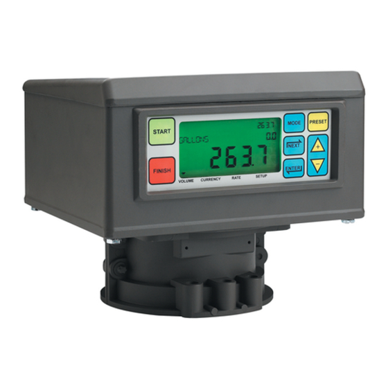
Introduction Display Head Display Head The EMR Display Head display features are shown in Figure 1 and Figure 2. Grand Totalizer Field Preset Indicator Operating Icons Preset Field MODE PRESET START Descriptor Field VEEDER ROOT CO NEXT Register Field FINISH ENTER VOLUME CURRENCY... -
Page 11: Boot-Up Test Sequence
Boot-Up Test Sequence Introduction Boot-Up Test Sequence When power is initiated to the Display Head, the screen will power up with a test sequence that satisfies the requirements of the local Weights and Measures authority. The Display Head test sequence follows below: •... -
Page 12: Activating The Display
Activating the Display Introduction • Subsequently, if no button press or operation occurs in 30 seconds, the display will go blank and wait for a button to be pressed to reactivate. Initially, when reactivated, the Display Head enters the Volume mode. Once the unit has been setup, the default reactivation mode will be the Pre-Dispense mode you choose in setup. -
Page 13: Display Button Functions - Standard Keypad
Introduction Display Button Functions - Standard Keypad • Printer - A page icon will display only when a printer is configured for the system. A slow flashing page icon is displayed when the printer is actively printing. A fast flashing page icon is displayed when the printer requires operator attention. -
Page 14: Data Entry
Data Entry Navigation Buttons The navigation buttons consist of the MODE, NEXT, ENTER, PRESET, and +/- buttons. They can be used to either select and set parameters, or select and set alpha and numeric values. • MODE - Press to navigate through the Modes; Setup, Volume, Currency, and Rate. •... -
Page 15: Data Entry With Optional Keypad
Data Entry with Optional Keypad Data Entry Data Entry with Optional Keypad Upon entering the Descriptor or Preset Field with the use of the navigation buttons the optional keypad will permit alpha and numeric entries. To enter a numeric in the Preset Field just select the appropriate button on the optional keypad. When a selection is made, the curser will automatically sequence to the position to the right. -
Page 16: Emr3 Operating States And Modes
Operating States and Modes System Operating States The system has three operating states, Pre-Dispense, Dispense, and Finish. PRE-DISPENSE STATE Prior to pressing the START button, the system is in the Pre-Dispense state. The setting of system parameters, pricing, and tax codes for a delivery are made in this state. DISPENSE STATE After pressing the START button (and selecting a product if setup for multiple products), the system enters the Dispense state. -
Page 17: Setup Mode
EMR3 Operating States and Modes System Operating Modes SETUP MODE The user can access the Setup Mode before a delivery to change a variety of parameters that are not required to be under weights & measure seal. Once the delivery state is active, the Setup Mode cannot be accessed. The Setup Mode is used to enter price codes, default mode setting, single flow and fast flow knock-off values and other non-metrological settings. -
Page 18: Setup Mode
Setup Mode Initiating the Setup Mode 1. Turn On power to the Display Head and wait until the boot-up sequence completes. 2. Depress the MODE button until the indicator at the bottom of the display points to Setup. 3. On initial power-up of the Display Head, the first Setup Mode category, PRICING, displays in the Descriptor Field. -
Page 19: Enter Security Code
Setup Mode Categories Setup Mode ENTER SECURITY CODE Figure 6 illustrates the initial logging in procedure using the default Passcode after Security Codes are enabled in C&C Mode (see Figure 51). Figure 7 shows the procedure for logging in using an assigned Passcode, and Figure 8 shows how to log out. -
Page 20: Pricing
Setup Mode Setup Mode Categories PRICING Figure 9 illustrates Pricing setup in Setup Mode. ENTER ENTER Press up/down PRICE CODE 1 PRICING NEXT NEXT to change digit CHANGE PRICE X PRICE X NEXT ENTER Press to accept and NEXT to ASSIGN TAX/DIS choice move to next digit.