Table of Contents
Advertisement
Quick Links
Click
here
to ask about the production status of specific part numbers.
MAX77962 Evaluation Kit
General Description
The MAX77962 evaluation kit (EV kit) is a fully assembled
and tested surface-mount printed circuit board (PCB) that
evaluates the MAX77962, a 3.2A USB Type-C
boost charger.
The MAX77962 EV kit includes the IC evaluation board
2
with integrated I
C communication interface and USB
micro-B cable. Windows
(GUI) software is available for use with the EV kit and can
be downloaded from Maxim's website at
tegrated.com/products/MAX77962
Resources tab). Windows 7 or newer is required to use
with the EV kit GUI software.
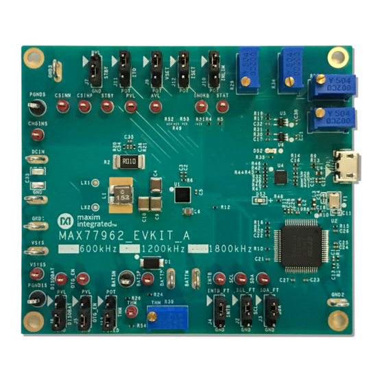
Figure 1. MAX77962 EV Kit Photo
®
USB Type-C
is a registered trademark of USB Implementers Forum.
Windows is a registered trademark and registered service mark of Microsoft Corporation.
319-100555; Rev 0; 6/20
®
-based graphical user interface
www.maximin-
(under the Design
Features
● Evaluates the MAX77962 USB Type-C Buck-Boost
Charger with Integrated FETs for 2S Li-Ion Batteries
®
buck-
● Demonstrates 3.5V to 23V Input Operating Range
● Demonstrates Charging Up to 3.2A
● Demonstrates USB-OTG Functionality
● Demonstrates JEITA Compliance with On-Board
Dummy Thermistors
● Assembled and Tested
2
● I
C Serial Interface
Ordering Information
Evaluates: MAX77962
appears at end of data sheet.
Advertisement
Table of Contents

Related Manuals for Maxim Integrated MAX77962


Summary of Contents for Maxim Integrated MAX77962
- Page 1 Evaluates: MAX77962 MAX77962 Evaluation Kit General Description Features The MAX77962 evaluation kit (EV kit) is a fully assembled ● Evaluates the MAX77962 USB Type-C Buck-Boost and tested surface-mount printed circuit board (PCB) that Charger with Integrated FETs for 2S Li-Ion Batteries ®...
-
Page 2: Quick Start
EV kit to the PC’s USB port. Setup Overview 5) Make jumper connections based on the Default Posi- A typical bench setup for the MAX77962 EV Kit is shown tion column in Table 1. Change it later when evaluat- Figure ing more features. - Page 3 Evaluates: MAX77962 MAX77962 Evaluation Kit 6) Connect a 2-cell Li-ion battery or simulated battery to 8) Launch the MAX77962 GUI software. the connectors labeled BATTP and BATTN. 9) Select Device > Connect from the window options to 7) Connect a DC power supply to the connectors labeled connect to the EV kit.
-
Page 4: Software Installation
Establish Communication Power up the MAX77962 by connecting a 2-cell Li-ion battery or simulated battery at BATTP/BATTN. Open the GUI software and select Device > Connect. A window should pop up showing that a slave address 0x69 (7-bit Figure 3. -
Page 5: Main Display
EV kit. To unlock register writing, select the 0x3 = and clicking Write (Figure 7), but only after the registers Unlocked option in the Charger Settings Protection have been unlocked. Figure 5. MAX77962 Top-Level Registers Maxim Integrated │ 5 www.maximintegrated.com... - Page 6 Evaluates: MAX77962 MAX77962 Evaluation Kit Figure 6. Charger Register Write Access Figure 7. Change CHGIN Input Current Limit after Unlocking Charger Settings Protection Maxim Integrated │ 6 www.maximintegrated.com...
- Page 7 Evaluates: MAX77962 MAX77962 Evaluation Kit Detailed Description of Hardware register. Writing 1 to this bit makes the value of the Fast Charge Current take effect. For changing Battery Charger Test Setup the fast-charge current, perform the following steps 1) Connect a 2-cell Li-Ion battery or simulated battery (Figure between BATTP and BATTN.
-
Page 8: Ordering Information
COILCRAFT 847-639-6400 www.coilcraft.com PANASONIC 800-344-2112 https://na.industrial.panasonic.com FUTURE TECHNOLOGY DEVICES INTL LTD 503-547-0988 www.ftdichip.com Note: Indicate that you are using the MAX77962 when contacting these component suppliers. Ordering Information PART TYPE MAX77962EVKIT-06# EV Kit MAX77962EVKIT-12# EV Kit #Denotes RoHS compliant. Maxim Integrated │ 8... - Page 9 Evaluates: MAX77962 MAX77962 Evaluation Kit MAX77962_06 EV Kit Bill of Materials REF_DES MFG PART # DESCRIPTION AVL, BATSP, CHGINS, CSINN, CSINP, DISQBAT, INOKB, INTB, 5000 RED MINI TESTPOINTS OTG_EN, PVL, SCL, SDA, STAT, STBY, THM, VSYSS BATTN, BATTP, DCIN, GND,...
- Page 10 Evaluates: MAX77962 MAX77962 Evaluation Kit MAX77962_06 EV Kit Bill of Materials (continued) REF_DES MFG PART # DESCRIPTION R9, R13 CRCW040227R0FK RES+, 27Ω, 1%, 0402 CRCW04021M00FK RES+, 1MΩ, 1%, 0402 CRCW04021K00FK RES+, 1KΩ, 1%, 0402 R12, R54 CRCW040210K0FK RES+, 10KΩ, 1%, 0402 CRCW04024752FK RES+, 47.5KΩ, 1%, 0402...
- Page 11 Evaluates: MAX77962 MAX77962 Evaluation Kit MAX77962_12 EV Kit Bill of Materials REF_DES MFG PART # DESCRIPTION AVL, BATSP, CHGINS, CSINN, CSINP, DISQBAT, INOKB, INTB, 5000 RED MINI TESTPOINTS OTG_EN, PVL, SCL, SDA, STAT, STBY, THM, VSYSS BATTN, BATTP, DCIN, GND,...
- Page 12 Evaluates: MAX77962 MAX77962 Evaluation Kit MAX77962_12 EV Kit Bill of Materials (continued) REF_DES MFG PART # DESCRIPTION CRCW04024R70FK RES+, 4.7Ω, 1%, 0402 CRCW040212K0FK RES+, 12KΩ, 1%, 0402 R9, R13 CRCW040227R0FK RES+, 27Ω, 1%, 0402 CRCW04021M00FK RES+, 1MΩ, 1%, 0402 CRCW04021K00FK RES+, 1KΩ, 1%, 0402...
- Page 13 Evaluates: MAX77962 MAX77962 Evaluation Kit MAX77962 EV Kit Schematic Diagram – Charger Maxim Integrated │ 13 www.maximintegrated.com...
- Page 14 Evaluates: MAX77962 MAX77962 Evaluation Kit MAX77962 EV Kit Schematic Diagram – Onboard I C Interface Maxim Integrated │ 14 www.maximintegrated.com...
- Page 15 MAX77962 EV Kit PCB Layout Diagrams 1.0” 1.0” MAX77962 EV Kit PCB Layout – Silkscreen Top MAX77962 EV Kit PCB Layout – Inner Layer 2 1.0” 1.0” MAX77962 EV Kit PCB Layout – Top Layer MAX77962 EV Kit PCB Layout – Inner Layer 3 Maxim Integrated │...
- Page 16 MAX77962 Evaluation Kit MAX77962 EV Kit PCB Layout Diagrams (continued) 1.0” 1.0” MAX77962 EV Kit PCB Layout – Inner Layer 4 MAX77962 EV Kit PCB Layout – Bottom Layer 1.0” 1.0” MAX77962 EV Kit PCB Layout – Inner Layer 5 MAX77962 EV Kit PCB Layout –...
-
Page 17: Revision History
For pricing, delivery, and ordering information, please visit Maxim Integrated’s online storefront at https://www.maximintegrated.com/en/storefront/storefront.html. Maxim Integrated cannot assume responsibility for use of any circuitry other than circuitry entirely embodied in a Maxim Integrated product. No circuit patent licenses are implied. Maxim Integrated reserves the right to change the circuitry and specifications without notice at any time.
Need help?
Do you have a question about the MAX77962 and is the answer not in the manual?
Questions and answers