Table of Contents
Advertisement
Quick Links
General Description
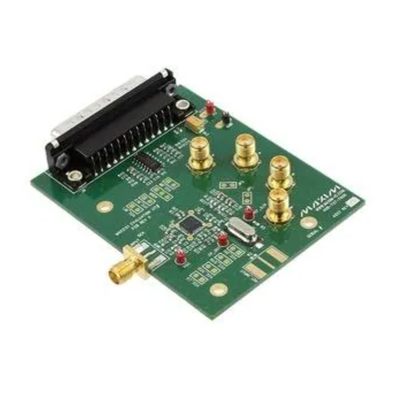
The MAX2121 evaluation kit (EV kit) simplifies the test-
ing and evaluation of the IC direct-conversion tuner. The
evaluation kit is fully assembled and tested at the factory.
Standard 50I SMA and BNC connectors are included
on the EV kit for the inputs and outputs to allow quick
and easy evaluation on the test bench. This document
provides a list of equipment required to evaluate
the device, a straightforward test procedure to verify
functionality, a description of the EV kit circuit, the circuit
schematic, a component list for the kit, and artwork for
each layer of the PCB.
DESIGNATION
QTY
Not installed, 3-pin (1 x 3) inline
ADDR
0
header, 0.01in centers
Sullins PEC36SAAN
CP_OUT, J13,
PC mini red test points
4
REF_O/P, VGC
Keystone 5000
1000pF Q10% ceramic
C1–C6, C9
7
capacitors (0603)
Murata GRM188R71H102K
C7, C13, C20,
0.1FF Q10% ceramic capacitors
C21, C25, C26,
8
(0603)
C27, C75
Murata GRM188R71C104K
C8, C12, C30
0
Not installed, capacitors
0.047FF Q10% ceramic
C10, C11
2
capacitors (0603)
Murata GRM188R71C473K
100pF Q5% ceramic capacitor
C14
1
(0603)
Murata GRM1885C1H101J
0.033FF Q10% ceramic capacitor
C15
1
(0603)
Murata GRM188R71E333K
2200pF Q5% ceramic capacitor
C16
1
(0603)
Murata GRM188R71H222J
For pricing, delivery, and ordering information, please contact Maxim Direct at
1-888-629-4642, or visit Maxim Integrated's website at www.maximintegrated.com.
DESCRIPTION
MAX2121 Evaluation Kit
Evaluates: MAX2121
S Easy Evaluation of the MAX2121
S 50I RF Input SMA Connector
S 50I Baseband Output BNC Connector
S Single 3.3V ±5% Supply
S I
2
C 2-Wire Serial Interface
S All Critical Peripheral Components Included
S Proven PCB Layout
S Fully Assembled and Tested
S PC Control Software
(Available at
www.maximintegrated.com/evkitsoftware
Ordering Information
appears at end of data sheet.
DESIGNATION
QTY
10FF Q10% tantalum capacitor
C18
1
(C Case)
AVX TAJC016K016
330pF Q5% ceramic capacitors
C23, C24, C71,
5
(0603)
C72, C73
Murata GRM1885C1H331J
5pF Q0.25pF ceramic capacitors
C28, C31
2
(0603)
Murata GRM1885C1H5R0C
33pF Q5% capacitor (0603)
C32
1
Murata GRM1885C1H330J
SMA PC top-mount connectors
IN, IP, QN, QP
4
Emerson 142-0701-201
DB25 right-angle male connector
J6
1
AMP 5747238-4
PC mini black test point
J17
1
Keystone 5001
JP1, JP2,
VCC_BB,
VCC_DIG,
Not installed, 2-pin (1 x 2) inline
VCC_LO,
0
headers, 0.01in centers
VCC_RF1,
Sullins PEC36SAAN
VCC_RF2,
VCC_SYN,
VCC_VCO
Features
)
Component List
DESCRIPTION
19-6059; Rev 1; 5/15
Advertisement
Table of Contents

Related Manuals for Maxim Integrated MAX2121EVKIT


Summary of Contents for Maxim Integrated MAX2121EVKIT
-
Page 1: General Description
Murata GRM188R71E333K headers, 0.01in centers VCC_RF1, Sullins PEC36SAAN VCC_RF2, 2200pF Q5% ceramic capacitor VCC_SYN, (0603) VCC_VCO Murata GRM188R71H222J For pricing, delivery, and ordering information, please contact Maxim Direct at 1-888-629-4642, or visit Maxim Integrated’s website at www.maximintegrated.com. 19-6059; Rev 1; 5/15... -
Page 2: Quick Start
RF signal generator capable of delivering at least • Network analyzer to measure return loss (optional) 0dBm of output power at frequencies up to 2.175GHz • Ammeter to measure supply current (optional) Windows and Windows XP are registered trademarks of Microsoft Corp. Maxim Integrated... - Page 3 150mA, and the supply current from the 3V V PCB ground plane. should read approximately 50FA. Be sure to adjust the power supply to account for any voltage drop across the ammeter. Maxim Integrated...
- Page 4 MAX2121 Evaluation Kit Evaluates: MAX2121 Figure 1. MAX2121 EV Kit Schematic Maxim Integrated...
- Page 5 MAX2121 Evaluation Kit Evaluates: MAX2121 Figure 3. MAX2121 EV Kit PCB Layout—Top Figure 2. MAX2121 EV Kit Component Placement Guide— Component Side Figure 4. MAX2121 EV Kit PCB Layout—Bottom Maxim Integrated...
- Page 6 MAX2121 Evaluation Kit Evaluates: MAX2121 Figure 5. MAX2121 EV Kit PCB Layout—Top Soldermask Figure 6. MAX2121 EV Kit PCB Layout—Bottom Soldermask Maxim Integrated...
- Page 7 MAX2121 Evaluation Kit Evaluates: MAX2121 Ordering Information PART TYPE MAX2121EVKIT# EV Kit #Denotes RoHS compliant. Maxim Integrated...
-
Page 8: Revision History
Maxim Integrated cannot assume responsibility for use of any circuitry other than circuitry entirely embodied in a Maxim Integrated product. No circuit patent licenses are implied. Maxim Integrated reserves the right to change the circuitry and specifications without notice at any time. The parametric values (min and max limits) shown in the Electrical Characteristics table are guaranteed.
Need help?
Do you have a question about the MAX2121EVKIT and is the answer not in the manual?
Questions and answers