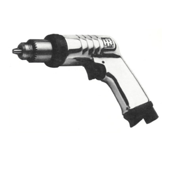
Ingersoll-Rand 5 Series Maintenance Information
Air screwdrivers
Hide thumbs
Also See for 5 Series:
- Product information (56 pages) ,
- Operation and maintenance manual (23 pages) ,
- Maintenance information (9 pages)
Summary of Contents for Ingersoll-Rand 5 Series
- Page 1 16575268 Edition 2 June 2009 Air Screwdrivers 5 Series Maintenance Information Save These Instructions...
- Page 2 WARNING Always wear eye protection when operating or performing maintenance on this tool. Always turn off the air supply and disconnect the air supply hose before installing, removing or adjusting any accessory on this tool or before performing any maintenance on this tool. Note: When reading the instructions, refer to exploded diagrams in parts Information Manuals when applicable (see under Related Documentation for form numbers).
- Page 3 208A 211 209 208 B 212A D1 Direct Drive Attachment With quick - change Bit Holder Non-rotating Finder (Dwg. TPB6801-1) C3 Adjustable Clutch Disassembly of the Adjustable Clutch Attachment for Non-Rotating nder Rotate the Adjusting Hole Cover (203) to expose the adjusting for Flat Bits hole in the Clutch Housing (201).
- Page 4 For Lever Throttle Models Disassembly of the Attachment, Gearing and Motor A leaking throttle is usually caused by a worn or damaged Throttle Lightly clamp the Tool, front end up, in copper-covered vise jaws. Valve Seat (12) and can be corrected by replacing this small washer For Pistol Grip Models, clamp the vise on the handle;...
- Page 5 For N ratio, slide a Gear Head Planet Gear (116) (13 teeth) onto Start the Adjusting Nut (214), indented side first, onto the Holder and run it finger tight against the compression of the Spring. each of the three gear shafts on the Gear Head (115). Enter the Install the Bit Holder Stop (216) in the groove.
- Page 6 Piped-away Exhaust A Piped-Away Exhaust Kit is available for Lever Throttle Models. To install it, slip the spring-type clamp over the length of lightweight flexible exhaust hose, then slide the exhaust hose over the hose whip and onto the rear of the Exhaust Deflector as shown in the illustration. Apply the clamp to the part of the hose over the annular groove in the Deflector.
- Page 7 Troubleshooting Guide Trouble Probable Cause Solution Loss of power Low air pressure Check air supply. For top performance, the air pressure must be 90 psig (6.2 bar/620 kPa) at the inlet. Plugged Air Strainer or Screen Inlet Screen Clean the Air Strainer or screen in a clean, suitable, cleaning solution.
- Page 8 www.ingersollrandproducts.com © 2009 Ingersoll Rand Company...


Need help?
Do you have a question about the 5 Series and is the answer not in the manual?
Questions and answers