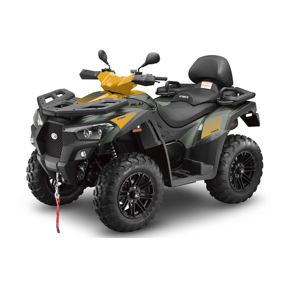
KYMCO MXU700i Manual
Hide thumbs Also See for MXU700i:
Table of Contents

Advertisement

FOREWORD ................................................................................................... i
PROTECT YOUR SPORT .................................................................................. i
IMPORTANT NOTICES ................................................................................... ii
SAFE RIDING INFORMATION ....................................................................... iii
PREFACE ...................................................................................................... iv
1.
1.1.
LABELS FOR T3b MODELS ........................................... 1-2
2.
SAFETY INFORMATION .................................................................. 2-1
3.
DESCRIPTION AND MACHINE IDENTIFICATION ............................. 3-1
3.1.
KEYS IDENTIFICATION NUMBER .................................. 3-1
3.2.
IDENTIFICATION NUMBER RECORDS .......................... 3-1
3.3.
ENGINE SERIAL NUMBER ............................................ 3-2
3.4.
ENGINE SERIAL NUMBER ............................................ 3-3
3.5.
PARTS LOCATIONS* ..................................................... 3-4
4.
CONTROL FUNCTIONS ................................................................... 4-1
4.1.
IGNITION SWITCH ....................................................... 4-1

TABLE OF CONTENTS

- 1 -
4.2.
INSTRUMENTS AND INDICATOR.................................. 4-2
4.3.
LEFT HANDLEBAR SWITCHES .................................... 4-15
4.4.
Winch switch ............................................................. 4-18
4.5.
EPS/ABS ..................................................................... 4-19
4.6.
TO JUMP START YOUR VEHICLE ................................ 4-20
4.7.
RIGHT HANDLEBAR SWITCH ..................................... 4-21
4.8.
THROTTLE LEVER ....................................................... 4-22
4.9.
SPEED LIMITER .......................................................... 4-23
4.10.
BRAKE ........................................................................ 4-24
4.11.
PARKING BRAKE ........................................................ 4-25
4.12.
LOCKING STEERING ................................................... 4-26
4.13.
DRIVE SELECT LEVER ................................................. 4-27
4.14.
FUEL TANK CAP ......................................................... 4-28
4.15.
SPARK PLUG INSPECTION .......................................... 4-29
4.16.
BATTERY INSPECTION................................................ 4-29
4.17.
SEAT ........................................................................... 4-30
4.18.
FLAG POLE BRACKET ................................................. 4-31
4.19.
TRAILER HITCH* ........................................................ 4-31

Advertisement

Table of Contents
loading

Summary of Contents for KYMCO MXU700i

  • Page 1: Table Of Contents

    TABLE OF CONTENTS FOREWORD ....................i 4.2. INSTRUMENTS AND INDICATOR........4-2 PROTECT YOUR SPORT .................. i 4.3. LEFT HANDLEBAR SWITCHES ........4-15 IMPORTANT NOTICES ................... ii 4.4. Winch switch ............. 4-18 SAFE RIDING INFORMATION ............... iii 4.5. EPS/ABS ..............4-19 PREFACE ......................
  • Page 2 TABLE OF CONTENTS 4.20. STORAGE COMPARTMENTS ........4-32 5.15. TIRE WEAR LIMIT ............5-14 4.21. ACCESSORY SOCKET ..........4-34 5.16. COOLANT ..............5-14 4.22. TRAILER SOCKET* ............4-35 OPERATION ................... 6-1 PRE-OPERATION CHECKS ............... 5-1 6.1. STARTING A COLD ENGINE .......... 6-1 5.1.
  • Page 3 TABLE OF CONTENTS DRUGS. 8.4. REAR GEAR BOX OIL ..........8-14 7.7. PRE-OPERATION CHECKS ..........7-7 8.5. FRONT GEAR BOX OIL ..........8-16 7.8. DO NOT OPERATE AT SPEEDS TOO FAST YOUR SKILLS OR 8.6. SPARK PLUG INSPECTION .......... 8-18 THE CONDITIONS.
  • Page 4 TABLE OF CONTENTS 8.22. HEADLIGHT BEAM ADJUSTMENT ......8-39 8.23. DRIVE SHAFT BOOTS ..........8-39 8.24. CABLE INSPECTION AND LUBRICATION ..... 8-40 8.25. TROUBLESHOOTING ..........8-41 CLEANING AND STORAGE ............. 9-1 9.1. CLEANING YOUR ATV........... 9-1 9.2. STORAGE ..............9-5 9.3.
  • Page 5: Foreword

    ATV are thoroughly inspected at various intervals. The information in this manual is based on the latest product data and specifications available at the time of printing. KYMCO Inc.
  • Page 6: Important Notices

    Speed Limitations (MPH) 10 - Governed 6-11 Up to 70 15 - Maximum KYMCO and the ATV Safety Institute recommend that all 15 - Governed ATV operators ride an ATV appropriate for their age. 12-15 Up to 90 30 - Maximum...
  • Page 7: Safe Riding Information

    SAFE RIDING INFORMATION KYMCO provide many important many safety messages both in this manual and on the vehicle. For your safety and the safety of others, pay special attention to all warning preceded by this alert symbol . Failure to follow the warnings contained in this manual can result in SEROUS INJURY or DEATH.
  • Page 8: Preface

    PREFACE Congratulations on your purchase of the KYMCO ATV. KYMCO take pride in a worldwide reputation for quality-in research, design, production and service. For replacement parts and accessories, we recommend genuine KYMCO products. They've been specially designed for your vehicle and manufactured to meet KYMCO's demanding standards.
  • Page 9: Location Of The Warning And Specification Labels

    ATV. The labels should be considered as permanent parts of the vehicle. If a label comes off or becomes hard to read, contact your KYMCO dealer for replacements. * The following illusts may differ slightly from your vehicle.
  • Page 10: Labels For T3B Models

    1.1. LABELS FOR T3b MODELS *FOR PASSENGER SEAT ONLY...
  • Page 11 MXU700i MXU550i...
  • Page 14: Safety Information

    2. SAFETY INFORMATION AN ATV IS NOT A TOY AND CAN BE HAZARDOUS TO OPERATE. An ATV handles differently from other vehicles including motorcycles and cars. A collision can occur quickly, even during routine maneuvers, if you fail to take proper pre-cautions. SEVERE INJURY OR DEATH can result if you do not follow these instructions: ...
  • Page 15  Never consume alcohol or drugs before or while operating this ATV.  Never operate at speeds too fast for your skills or the conditions. Always go at a speed that is proper for the terrain, visibility and operating conditions, and your experience. ...
  • Page 16  Never operate the ATV on hills.  Always follow proper procedures for climbing slopes as described in this manual. Check the terrain carefully before you start up any slope. Shift your weight forward. Never open the throttle suddenly. Never go over the top of a slope at high speed. ...
  • Page 17  Never operate an ATV in fast flowing water or in water that deeper than recommended in this manual. Remember that wet brakes may have reduced stopping ability. Test your brakes after leaving water. If necessary, apply them several times to let friction dry out the linings.
  • Page 18 POTENTIAL HAZARD POTENTIAL HAZARD Improper handling of gasoline. Improper handling of gasoline. WHAT CAN HAPPEN WHAT CAN HAPPEN Gasoline can catch fire and you could be burned. Gasoline is poisonous and can cause injuries. HOW TO AVOID THE HAZARD HOW TO AVOID THE HAZARD Always turn off the engine when refueling.
  • Page 19 POTENTIAL HAZARD Starting or running the engine in a closed area. WHAT CAN HAPPEN Exhaust fumes are poisonous and may cause loss of consciousness and death within a short time. HOW TO AVOID THE HAZARD Always operate your machine in an area with adequate ventilation.
  • Page 20: Description And Machine Identification

    3. DESCRIPTION AND MACHINE IDENTIFICATION 3.1. KEYS IDENTIFICATION NUMBER 3.2. IDENTIFICATION NUMBER RECORDS The keys identification number is stamped on itself or a tag as Record the keys identification number, frame serial number and shown in the following illustration. engine serial number information for assistance when order replacement parts.
  • Page 21: Engine Serial Number

    3.3. ENGINE SERIAL NUMBER The engine serial number is stamped on the left crankcase. Engine Serial Number...
  • Page 22 3.4. FRAME NUMBER The frame number is stamped on the right side of vehicle.
  • Page 23: Parts Locations

    3.5. PARTS LOCATIONS* * The following illusts may differ slightly from your vehicle. (01) Rearview mirrors * (02) Position lights (03) High beam head light (04) Low beam headlight (05) Right turn signal light (06) Winch * (07) Left turn signal light *SOME MODELS ONLY NOTE The figures of machine you purchased may differ slightly...
  • Page 24 (08) Left rear turn signal light (09) Cup holder (10) Drive select lever (11) Central storage compartment (12) Tool storage (13) Taillights/ Brake lights (14) Right rear turn signal light (15) Spark arrester (16) Trailer hitch* (17) License light (18) Trailer socket *SOME MODELS ONLY NOTE The figures of machine you purchased may differ slightly...
  • Page 25 (19) Front cargo rack (20) Battery/ Fuse/ Reservoir water tank (21) Rider Seat (22) Passenger Seat * (23) Exhaust system (24) Rear cargo rack (25) Left foot peg * *SOME MODELS ONLY NOTE The figures of machine you purchased may differ slightly from this manual.
  • Page 26 (26) Seat lock lever * (27) Tool kit (28) Fuel fill cap (29) Accessory socket (30) Battery cut off switch (31) Brake pedal fluid reservoir (32) Right foot peg * (33) Oil level inspection window (34) Rear brake pedal *SOME MODELS ONLY NOTE The figures of machine you purchased may differ slightly from this manual.
  • Page 27 (35) Winch switch * (36) Rear brake lever (37) Headlight dimmer switch (38) Rear parking brake lever Starter button Hazard switch Turn signal switch Horn switch (39) Ignition switch (40) 2WD/4WD select switch (41) Throttle Lever (42) Front brake lever/ Front and differential lock parking *SOME MODELS ONLY...
  • Page 28: Control Functions

    4. CONTROL FUNCTIONS 4.1. IGNITION SWITCH Functions of the respective switch positions are as follows: OFF: All electrical circuits are switched off except hazard light. The key can be removed in this position. All electrical circuits are switched on. The engine can be started.
  • Page 29: Instruments And Indicator

    4.2. INSTRUMENTS AND INDICATOR (12) Brake Level Warning Indicator Mode Button This button is used to switch km/h, mph, km and mile. This button is also used to adjust the time and reset the trip of meter. MODE Button Engine Tachometer Engine Tachometer The electronic tachometer allows the rider to monitor the ADJ Button...
  • Page 30 ADJ Button Multi-Function Display This button is used to select ODO, TRIP A and TRIP B. The display includes the following functions:  Digital clock This button is also used to adjust the time and reset the  4WD/ 2WD/ LOCK indicator tripmeter.
  • Page 31 Stop driving immediately and see If something is wrong with the ABS, the indicator comes on and an authorized KYMCO dealer to have the system checked remains it. When the indicator light is on, the ABS doesn’t...
  • Page 32 4.2.1. Multi-function display 4.2.2. Change Units On ODO mode, press and hold MODE button for more than 2 seconds to switch units. The speed unit and mileage unit will be switched in the same time. Digital clock 4WD/ 2WD/ LOCK indicator Gear Select Display Speedometer Battery Voltage...
  • Page 33 Digital clock The clock shows the time in 24-hour format while the ignition Press and hold both the MODE button and ADJ button in switch is ON. the same time for more than 2 seconds. The clock will be set in the adjust mode with the hour display flashing. To adjust the time manually, proceed as follows: Turn the ignition switch ON.
  • Page 34 To set the hour, press the ADJ button until the desired Press the MODE button, the minute display will start hour. flashing.
  • Page 35 To set minute, press the ADJ button until the desired To end the adjustment, Press and hold the MODE button minute. and ADJ button in the same time until the digital clock stop flashing.
  • Page 36 4WD/ 2WD/ LOCK indicator 4WD indicator Differential lock indicator Shows the drive mode is in the 4WD. The front axle is equipped with a lockable differential that Shows the drive mode isn’t in the 2WD. allows the operator to choose between an open differential or a closed differential in low traction situations.
  • Page 37 Gear Select Display Battery Voltage Display the current gear position. Display the current battery voltage. Speedometer Display the riding speed in km/h or mph. 4-10...
  • Page 38 Fuel gauge The fuel gauge shows the approximate fuel supply available in a graduated display. The normal operating fuel range is with the section between the segment F and segment E. The fuel indicator and the last square start flashing when the remaining fuel is low and you should refill the tank as soon as possible.
  • Page 39 Odometer/ Trip meter/ Engine Running Time/ OPC Change Unit The odometer shows the total mileage in Km or in mile. To change the unit, on ODO mode, press and hold MODE The trip meter shows the trip distance in Km or in mile. There is button for more than 2 seconds to switch unit.
  • Page 40 Reset Tripmeter Press ADJ select tripmeter. Press and hold both the MODE button and ADJ button in the same time until the tripmeter is reset. 4-13...
  • Page 41 Operator Presence Control (OPC)* *T3b MODELS ONLY After 10 seconds, the operator presence control (OPC) activates an alarm signal and "OPC" appears on the gauge display when the any of following conditions is fulfilled:  Ignition is switched on or the engine is running below the 1800 rpm.
  • Page 42: Left Handlebar Switches

    4.3. LEFT HANDLEBAR SWITCHES 4.3.2. Turn signal switch Use the turn signal switch while turning to another direction or shifting to another lane. The turn signal light will flash when the switch is operated and ignition switch is ON. "" For turning to the "left". ""...
  • Page 43 4.3.3. Hazard switch When the hazard switch is pressed, the right and left turn signal lights flash together. The instrument turn signal indicator light will also flash when the switch is operated. When the hazard switch is released, the right and left turn signal lights go out together.
  • Page 44 4.3.5. Engine stop switch The engine stop switch is used to stop the engine in an emergency, such as engine overturns or when the throttle cable is stuck If your ATV is stopped with the ignition switch ON and the engine stop switch OFF the battery will discharge.
  • Page 45: Winch Switch

    4.4. Winch switch Start switch To control cable in and out To determine the Cable OUT, trigger to the “OUT” position To determine the Cable IN, trigger to the “IN” position 4.3.6. Start switch The start switch is used for starting the engine. Pushing the If you want to stop winching, please release the trigger switch in starts the engine.
  • Page 46 CAUTION serious driving problems. If such components need service, Use of non- recommended tires may cause malfunctioning of ABS and see an authorized KYMCO dealer lead to extended braking distance. The rider could have an accident as NOTE a result. Always use standard for this recommended vehicle .
  • Page 47: To Jump Start Your Vehicle

    TO JUMP START YOUR VEHICLE Now connect the black negative (-) cable to the good Remove the seat and locate the batteries. battery’s negative (-) terminal. Find the positive (+) and negative (-) terminals on each Don’t let the other end touch anything until the next step. battery.
  • Page 48: Right Handlebar Switch

    4.6. RIGHT HANDLEBAR SWITCH 4.6.1. 2WD/4WD Select Button This ATV is equipped with a 2WD/4WD select button, which permits a choice between the “2WD”and “4WD” drive modes. Select a drive mode that is suitable for your riding. The 2WD/4WD select button is located above the throttle lever. To select the drive mode, push the button to switch to the desired position.
  • Page 49: Throttle Lever

    Check the operation of the throttle lever before you start the engine. If it does not work smoothly, check for the cause. Correct the problem before riding the ATV. Consult a KYMCO dealer if you can't find or solve the problem yourself.
  • Page 50: Speed Limiter

    4.8. SPEED LIMITER The speed limiter keeps the throttle from fully opening, even when the throttle lever is pushed to the maximum. Screwing in POTENTIAL HAZARD the adjuster limits the maximum engine power available and Improper adjustment of the speed limiter and throttle. decreases the maximum speed of the ATV.
  • Page 51: Brake

    4.9. BRAKE 4.9.1. Front Brake Lever 4.9.3. BRAKE PEDAL The front brake lever is next to the right handgrip. This ATV is equipped with a combined brake system. Operating The front brakes are operated by squeezing the front brake the brake pedal applies the rear brake and the front lever.
  • Page 52: Parking Brake

    4.10. PARKING BRAKE 4.10.1. Front parking brake 4.10.2. Rear parking brake To set the front parking brake, squeeze the front brake lever To set the rear parking brake, move the lever to position (A). and lock it with the lock lever. Always set the parking brake Only set the parking brake when parking and before when parking and before starting the engine.
  • Page 53: Locking Steering

    4.11. LOCKING STEERING Turn the steering handlebar right completely and turn the key clockwise to lock the steering handlebar. POTENTIAL HAZARD The key can be taken out. Improper use of the parking brake. Turn the key counterclockwise to unlock. WHAT CAN HAPPEN The ATV could start moving unexpectedly if the parking brake is not applied before starting the engine.
  • Page 54: Drive Select Lever

    POTENTIAL HAZARD Improper use of the locking steering. WHAT CAN HAPPEN The ATV could cause loss of control or overturn. HOW TO AVOID THE HAZARD Always be sure you have released the locking steering handlebar and steering lock key is taken out before you begin to ride.
  • Page 55: Fuel Tank Cap

    4.13. FUEL TANK CAP 4.13.1. Fuel System Troubleshooting After refueling, be sure to tighten the fuel tank cap until it is secure. Engine would not start acceleration To refuel refer to CH 5.35.3. Intake air leak Fuel contaminated/deteriorated Pinched or clogged fuel hose. Faulty fuel pump Engine stall, hard to start, rough idling Intake air leak...
  • Page 56: Spark Plug Inspection

    4.14. SPARK PLUG INSPECTION 4.15. BATTERY INSPECTION If the plug is oily or has carbon built up it, have it cleaned, Checking the battery voltage if the cold engine start-ambient preferably in a sand-blasting device, and then clean off any temperature below -180C (00F).
  • Page 57: Seat

    4.16. SEAT 4.16.1. OPEN 4.16.3. PASSENGER SEAT* To remove the seat, pull the seat lock lever upward and pull up *EPS MODELS ONLY the seat at the rear. To remove the seat, pull the passenger seat lock lever upward and pull up the seat. Seat lock lever NOTE 4.16.2.
  • Page 58: Flag Pole Bracket

    4.17. FLAG POLE BRACKET 4.18. TRAILER HITCH* Flag poles are optional equipment available from your KYMCO *SOME MODELS ONLY dealer. To mount a flag pole in the bracket to make you more The trailer hitch is located on the rear axle housing. To use the visible.
  • Page 59: Storage Compartments

    4.19. STORAGE COMPARTMENTS 4.19.1. Cup Holder Your ATV provides three storage spaces that the owner’s manual and some tools can put inside so you’ll have it with you for easy reference. Put your drink at cup holder (1). Store your owner’s manual in central storage compartment (2).
  • Page 60 4.19.2. Central Storage Compartment 4.19.3. Right Storage Compartment Turn the knob counterclockwise to open. Use the key to open the compartment. Turn the knob clockwise to lock. Turn the key clockwise to open. Turn the key counterclockwise to lock. The owner’s manual should be stored in the plastic bag before store in the storage compartment.
  • Page 61: Accessory Socket

    4.20. ACCESSORY SOCKET The accessory socket (5V / 2.1A) is located on the right side of To use the accessory socket: the central storage compartment. You can use the accessory Turn the ignition switch ON, and then start the engine. socket to power a trouble light, spotlight, radio, or cell phone, Turn the headlights OFF.
  • Page 62: Trailer Socket

    4.21. TRAILER SOCKET* 4.21.1. Socket Wiring Function Color The trailer socket is located at the rear side of the vehicle. Brake Light It is only allowed to provide vehicle lighting on the trailer LH Turn Fog Light Signal L(1) LH Indicator BR/R RH Indicator BR/Y...
  • Page 63: Pre-Operation Checks

    5. PRE-OPERATION CHECKS Before using this machine, check the following points ITEM ROUTINE CHAPTER DRIVE SELECT LEVER CH 5.1 Check the lever for proper operation Check operation, condition, and brake fluid level BRAKE CH 5.2 Fill with DOT 4 brake fluid if necessary Check fuel level.
  • Page 64: Drive Select Lever

    5.1. DRIVE SELECT LEVER POTENTIAL HAZARD Before shifting, you must stop the machine and return the Failure to inspect the ATV before operating. Failure to properly throttle lever to its closed position until the engine speed to the maintain the ATV. specified idling speed.
  • Page 65 POTENTIAL HAZARD Operating with improperly adjusted drive select lever. WHAT CAN HAPPEN You may lose control of the gear shifting, which lead to accident. HOW TO AVOID THE HAZARD Make sure moving the shift lever into the "N" position and neutral indicator lamp comes on before start the engine.
  • Page 66 5.1.1. Drive Select Lever Adjustment Shift the transmission to neutral and turn the ignition switch OFF and wait the engine cools down Remove the seat. Remove the front cover. Remove five fasteners, and then remove the central storage compartment cover and gear shifter handle. Remove five fasteners, remove the left side cover.
  • Page 67 Verify the length of the shift rod is 341.5mm (± 0.5mm). To adjust the length by loosening the lock nuts (1) and rotating the shift rod (2) until you achieve the proper length (150mm) then tighten both locknuts firmly.
  • Page 68: Front And Rear Brakes

    ATV if you find any problem with the brakes. If a problem inspect the brakes for wear. cannot be corrected by the adjustment procedures provided in this manual, have the ATV inspected by a KYMCO dealer.
  • Page 69: Fuel

    5.3. FUEL Fill the fuel tank when necessary and make sure there is Your KYMCO engine has been designed to use regular sufficient gasoline in the tank. unleaded gasoline with a pump octane number of 86 or higher, Check for leaks.
  • Page 70: Drive Shaft Boots

    5.4. DRIVE SHAFT BOOTS Check the rubber drive shaft boots for damage or leaking grease. If necessary, have your KYMCO dealer replace them. POTENTIAL HAZARD Improper care when refueling. WHAT CAN HAPPEN Fuel can spill, which can cause a fire and severe injury. Fuel expands when it heats up.
  • Page 71: Engine Oil

    5.5. ENGINE OIL Make sure the engine oil at the specified level. Add oil as necessary. Be sure to use motor oils that do not contain anti-friction modifiers. Passenger car motor oils (often labeled "Energy Check for leaks. Conserving") contain anti-friction additives which will cause starter clutch slippage, resulting in reduced component life and poor engine performance.
  • Page 72: Rear Gear Case Oil

    5.6. REAR GEAR CASE OIL 5.7. FRONT GEAR CASE OIL Make sure the rear gear case oil at the specified level. Add oil Make sure the front gear case oil at the specified level. Add oil as necessary. as necessary. Check for leaks.
  • Page 73: Throttle Lever

    5.9. FITTINGS AND FASTENERS Always check the tightness of chassis fittings and fasteners before a ride. Take the machine to a KYMCO dealer or refer to the Service Manual for correct tightening torque. 5.10. LIGHTS Check the headlight and taillight to make sure they are in working condition.
  • Page 74: Tires

    5.13. TIRES The tires should be set to the recommended pressure. Recommended tire pressure Front 34~41 kpa (0.35~0.41 kgf/cm , 5.1~5.9 psi) POTENTIAL HAZARD Operating this ATV with improper tires, or with improper or Rear 31~37 kpa (0.32~0.38 kgf/cm , 4.6~5.4 psi) ...
  • Page 75: How To Measure Tire Pressure

    Set tire pressures to the following Use the low-pressure tire gauge. (Tool kit) MXU 700i MXU700i/ NOTE Item MXU500i / T3B MXU700i T3B MXU 700i (EPS Models) The low-pressure tire gauge is included as standard 0.38kgf/cm2 0.35kgf/cm2 0.38kgf/cm2 equipment. Make two measurements of the tire pressure and Front (5.5 psi)
  • Page 76: Tire Wear Limit

    5.15. TIRE WEAR LIMIT 5.16. COOLANT When the tire groove decreases to 4 mm (0.16 in) due to wear, Check the coolant level in the reservoir tank when the engine is replace the tire. cold. (The coolant level will vary with engine temperature.) The coolant level is satisfactory if it is between the "FULL"...
  • Page 77 Coolant reservoir cap Always use a thick rag over the cap. Allow any remaining Maximum level mark pressure to escape before completely removing the cap. Minimum level mark Should be serviced by your authorized KYMCO dealer when changing the coolant. 5-15...
  • Page 78: Operation

    Read the Owner's Manual carefully. If there is a control or HOW TO AVOID THE HAZARD function you do not understand, ask your KYMCO dealer. When riding in cold weather, always make sure all control cables work smoothly before you begin riding.
  • Page 79 When the select lever is in the neutral or park position, if start-ambient temperature below -18 C (0 F). either indicator light does not come on, ask a KYMCO dealer to inspect its electric circuit. Completely close the throttle lever and start the engine...
  • Page 80: Starting A Warm Engine

    NOTE NOTE  If the engine fails to start, release the start switch, then Do not allow water enter the right case. push the start switch again.  Each cranking should be as short as possible to preserve battery energy. Do not crank the engine more than 10 seconds on each attempt.
  • Page 81: Drive Select Lever

    6.3. DRIVE SELECT LEVER Before shifting, you must stop the machine and return the throttle lever to its closed position until the engine speed to the specified idling speed. Otherwise, the transmission may be damaged. NOTE Apply the rear brake and shift the shift lever into P position before turning off the engine when parking the vehicle on an incline if you park on an incline with shift lever in H, L or R (L) Low...
  • Page 82 When you shift into reverse, make sure there are no obstacles guide. or people behind you. When it is safe to proceed, go slowly. NOTE When in reverse, the reverse indicator light should be on. If the light does not come on, ask a KYMCO dealer to inspect the machine.
  • Page 83: Engine Break-In

    Each full throttle acceleration sequence should be followed with occasionally. a substantial rest period for the engine by cruising at lower r/min so the engine can rid itself of the temporary buildup of heat. If any abnormality is noticed during this period, consult a KYMCO dealer.
  • Page 84: Parking

    6.5. PARKING When parking, stop the engine and shift into the park position. To set the rear parking brake, see CH.4.9.2. Turn the fuel valve to "OFF" and apply the parking brake. The front brake lever has three locked position that allow it to be used as a parking brake.
  • Page 85 6.5.1. Parking on a slope Bring the machine to a stop by applying the brakes. Stop the engine. POTENTIAL HAZARD With the brake applied, shift the drive select lever into the Parking on a slope or other incline. park position WHAT CAN HAPPEN Apply the parking brake.
  • Page 86: Accessories

    Other accessories may also be available on seat, or one that limits your view. the market. However, it is not possible for KYMCO to test  all non-KYMCO accessories, nor have any control over Use extra caution when riding an ATV with accessories.
  • Page 87: Loading

    6.7. LOADING 6.7.2. One Rider with Passenger As originally equipped, this ATV can carry cargo or tow a trailer, you must use common sense and good judgment. Keep the As originally equipped, this ATV can carry cargo or tow a trailer, following points in mind: you must use common sense and good judgment.
  • Page 88  Load cargo on the cargo racks as close to the center of the vehicle as possible. Put cargo at the rear of the front POTENTIAL HAZARD cargo rack and at the front of the rear cargo rack. Center Overloading this ATV or carrying or towing cargo improperly. the load from side to side.
  • Page 89: Riding Your Atv

    7. RIDING YOUR ATV...
  • Page 90: Getting To Know Your Atv

    This kind of table indicates a potential hazard that could result in serious injury or death. 7.1. GETTING TO KNOW YOUR ATV Before you begin to ride, be sure you have read this Owner's This ATV is for recreation and utility use. This section, riding manual completely and understand the operation of the your ATV, provides general ATV riding instructions for controls.
  • Page 91: Ride With Care And Good Judgement

    7.2. RIDE WITH CARE AND GOOD JUDGEMENT Get training if you are inexperienced. POTENTIAL HAZARD Beginners and inexperienced riders should get proper Operating this ATV without proper instruction. instruction on how to operate this ATV. WHAT CAN HAPPEN The risk of an accident is greatly increased if the operator does Riding your machine requires skills acquired through not know how to operate the ATV properly in different situations practice over a period of time.
  • Page 92: Not Recommended For Children Under 16 Year Of

    7.3. NOT RECOMMENDED FOR CHILDREN 7.4. NEVER CARRY PASSENGER ON THE UNDER 16 YEAR OF AGE. CARGO RACKS. POTENTIAL HAZARD POTENTIAL HAZARD Failure to follow the age recommendations for this ATV. Carrying a passenger on the cargo racks. WHAT CAN HAPPEN WHAT CAN HAPPEN Use by children of ATVs that are not recommended for their Greatly reduces your ability to balance and control this ATV.
  • Page 93: Apparel

    7.5. APPAREL HOW TO AVOID THE HAZARD POTENTIAL HAZARD Always wear an approved motorcycle helmet that fits properly. Operating this ATV without wearing an approved motorcycle You should also wear: helmet, eye protection and protective clothing. eye protection(goggles or face shield) gloves WHAT CAN HAPPEN boots Operating without an approved motorcycle helmet increases...
  • Page 94: Do Not Operate After Consuming Alcohol Or

    7.6. DO NOT OPERATE AFTER CONSUMING ALCOHOL OR DRUGS. Operator's performance capability is reduced by the influence POTENTIAL HAZARD of alcohol or drugs. Operating this ATV after consuming alcohol or drugs. WHAT CAN HAPPEN Could seriously affect your judgment. Could cause you to react more slowly.
  • Page 95: Pre-Operation Checks

    7.7. PRE-OPERATION CHECKS Always perform the pre-operation checks listed on CH 5 before riding for safety and proper care of the machine. POTENTIAL HAZARD POTENTIAL HAZARD Failure to inspect the ATV before operating. Failure to properly Operating this ATV with improper tires, or with improper or maintain the ATV.
  • Page 96: The Conditions

    7.8. DO NOT OPERATE AT SPEEDS TOO FAST YOUR SKILLS OR THE 7.8.1. Speed limiter CONDITIONS. For riders inexperienced with this model, this model is equipped with a speed limiter in the throttle lever housing. The speed limiter limits the power and top speed of the machine. POTENTIAL HAZARD Turning the screw in decreases top speed, and turning it out Operating this ATV at speeds too fast for your skills or the...
  • Page 97: Loading And Accessories

    7.9. LOADING AND ACCESSORIES 7.9.4. Loading and operational guidelines Use extra caution when riding the machine with additional loads, such as accessories or cargo. Carrying cargo will affect how your ATV handles and greatly The machine's handling may be adversely affected. Reduce reduce its ability in accelerating, braking and making turns and your speed when adding additional loads.
  • Page 98 7.9.5. Accessories Genuine KYMCO accessories have been specifically designed for and tested on this vehicle. Because KYMCO cannot test all POTENTIAL HAZARD other accessories, you are personally responsible for properly Overloading this ATV or carrying or towing cargo improperly. selecting, installing, and using non-KYMCO accessories.
  • Page 99: Modifications

    Never modify this ATV through improper installation or use of accessories. All parts and accessories added to this vehicle should be genuine KYMCO or equivalent components designed for use on this ATV and should be installed and used according to instruction. If you have question, consult an authorized ATV dealer.
  • Page 100: During Operation

    7.11. DURING OPERATION Always keep your feet on the footboards during operation. Otherwise your feet may contact the rear wheels. POTENTIAL HAZARD Removing hands from handlebars or feet from footboards during operation. WHAT CAN HAPPEN Removing even one hand or foot can reduce your ability to control the ATV or could cause you to lose your balance and fall a foot peg, your foot or leg may come into contact with the rear wheels, which could injure you or cause an accident.
  • Page 101 POTENTIAL HAZARD Attempting wheelies, jumps, and other stunts. WHAT CAN HAPPEN Increases the chance of an accident, including an overturn. HOW TO AVOID THE HAZARD Never attempt stunts, such as wheelies or jumps. Don't try to show off. Avoid wheelies and jumping. You may lose control of the machine or overturn.
  • Page 102: Exhaust System

    7.12. EXHAUST SYSTEM The exhaust on the machine is very hot during and following operation. To prevent burns, avoid touching the exhaust system. POTENTIAL HAZARD Park the machine in a place where pedestrians or children are Hot exhaust system not likely to touch it. WHAT CAN HAPPEN Someone touching the exhaust system during or after operation could be burned.
  • Page 103: Practicing

    7.13. PRACTICING Select a flat area to become familiar with your ATV. Make sure With the engine idling, return the starter knob to the closed that this area is free of obstacles and other riders. You should position and shift the drive select lever into the forward position. practice control of the throttle, brakes, shifting before trying Then release the parking brake.
  • Page 104: Turning Your Atv

    7.14. TURNING YOUR ATV To achieve maximum traction while riding on-road, the two rear wheels are mounted solidly on one axle and turn together at the POTENTIAL HAZARD same speed. Therefore, unless the wheel on the inside of the Turning improperly turn is allowed to slip or lose some traction, the ATV will resist WHAT CAN HAPPEN turning.
  • Page 105: Climbing Up Slope

    7.15. CLIMBING UP SLOPE Use proper riding techniques to avoid vehicle overturns on slopes. Be sure that you can maneuver your ATV well on flat POTENTIAL HAZARD ground before attempting any incline and then practice riding Operating on excessively steep slopes. first on gentle slopes.
  • Page 106 An obstacle or a sharp drop could be on the other side of POTENTIAL HAZARD the slope. Climbing slopes improperly WHAT CAN HAPPEN Could cause loss of control or cause the ATV to overturn. HOW TO AVOID THE HAZARD Always follow proper procedures for climbing slopes as described in this Owner's Manual.
  • Page 107 If you are climbing a slope and you find that you have not properly judged your ability to make it to the top, you should POTENTIAL HAZARD turn the ATV around while you still have forward motion Improperly crossing slopes or turning on slopes. (provided you have the room to do so) and go down the slope.
  • Page 108 If your ATV has stalled or stopped and you believe you can When descending slope, using either brake lever or the brake continue up the slope, restart carefully to make sure you do not pedal will brake the wheels on the downslope side. Avoid lift the front wheels which could cause you to lose control.
  • Page 109 2WD: Never apply the rear brake while rolling backwards. Apply the front brake. POTENTIAL HAZARD 4WD: Apply both front and rear brakes gradually. Stalling, rolling backwards or improperly dismounting while When fully stopped, shift to the parking position “P”. climbing a slope. When fully stopped, apply front brake as well, and then lock WHAT CAN HAPPEN parking brake.
  • Page 110 If the slope is not too steep and you have good footing, you If the slope is too steep or too slippery, or if you have any doubt may be able to walk the ATV back down the slope. Make sure whether you can safely walk the ATV back down the slope, your intended path is clear in case you lose control of the ATV.
  • Page 111: Riding Down Slope

    7.16. RIDING DOWN SLOPE When riding your ATV down slope, shift your weight as far to Use caution while descending a slope with loose or slippery the rear and up slope side of the ATV as possible. Move back surfaces. Braking ability and traction may be adversely affected on the seat and sit with your arms straight.
  • Page 112 Whenever possible, ride your ATV straight down slope. Avoid sharp angles which could allow the ATV to tip or roll over. POTENTIAL HAZARD Carefully choose your path and ride no faster than you will be Going down a slope improperly. able to react to obstacles which may appear.
  • Page 113: Parking

    7.17. PARKING Always choose a level place to park. After bringing your ATV to a stop, hold the brakes while you shift into park position. Then set the parking brake and turn the ignition switch OFF. If you're through riding for the day, also turn the fuel valve OFF. 7.18.
  • Page 114: Periodic Maintenance And Adjustment

    Moving parts can catch clothing or parts of the body, causing injury. Electrical components can cause shocks or can start fires. HOW TO AVOID THE HAZARD Turn off the engine when performing maintenance unless otherwise specified. Have KYMCO dealer perform service if you are not familiar with machine service.
  • Page 115: Tool Kit/Tool Kit Compartment

    The tools in the kit are sufficient to perform routine Standard/Phillips screwdriver maintenance and simple repairs. Any extensive work requiring Spark plug wrench (A) additional tools should be performed by your authorized 10/12 mm wrench KYMCO dealer. Air pressure gauge Rear cushion adjuster Spark plug wrench (B)
  • Page 116 Never modify this ATV through improper installation or use of accessories. All parts and accessories added to this vehicle should be genuine KYMCO or equivalent components designed for use on this ATV and should be installed and used according to instructions. If you have questions, consult an...
  • Page 117: Periodic Maintenance/Lubrication

    8.2. PERIODIC MAINTENANCE/LUBRICATION INITIAL EVERY WHICHEVER COMES FIRST mile 1200 ITEM 1000 2000 ROUTINE Month    Engine oil Replace (Warm engine before draining) Clean    Oil strainer* Replace if necessary    Engine oil filter cartridge Replace Check oil level/oil leakage ...
  • Page 118 INITIAL EVERY WHICHEVER COMES FIRST mile 1200 ITEM 1000 2000 ROUTINE Month Check fuel hose for cracks or damage   Fuel line* Replace if necessary Check valve clearance    Valves* Adjust if necessary Check operation and brake fluid ...
  • Page 119 Knuckle shafts/ Steering shaft* Lubricate every 6 months Check all chassis fittings and fasteners    Fittings and Fasteners* Correct if necessary *: It is recommended that these items be serviced by a KYMCO dealer. **: Lithium soap base grease.
  • Page 120: Engine Oil

    8.3. ENGINE OIL 8.3.1. Engine oil level measurement Place the machine on a level place. Warm up the engine for several minutes and stop it. Check the oil level through the inspection window. The oil level should be between the maximum (H) and minimum (L) marks.
  • Page 121 8.3.2. Engine oil replacement and oil filter cleaning Place the machine on a level place. Warm up the engine for several minutes and stop it. Place a container under the engine. Remove the oil fill cap (1) and oil filter cap (2) to drain the oil.
  • Page 122 Clean the oil strainer with solvent. ENGINE OIL QUANTITY(550/700) Inspect the O-ring and replace if damaged. 2.4 L (2.11 Imp 3.0L (2.64 lmp Periodic oil change qt,3.18 US qt) qt, 2.54 US qt) Reinstall the O-ring, oil strainer, compression spring and After draining and oil filter 3.2 L (2.82 lmp 2.6 L (2.29 lmp...
  • Page 123 8.3.3. 8-10Engine oil replacement (with or without oil filter cartridge replacement) Place the machine on a level place. Warm up the engine for several minutes and stop it. Place a container under the engine. Remove the oil fill cap (1) and drain plug/washer (2) to drain the oil.
  • Page 124 NOTE Skip steps E to I if the oil filter cartridge is not being replaced. Remove the two fasteners and then remove front cover. Remove the four fasteners and then remove the central storage cover. Remove the five fasteners and then remove the right side cover.
  • Page 125 Remove the oil filter cartridge (3) with an oil cartridge wrench. NOTE An oil cartridge wrench is available at a nearby KYMCO dealer NOTE Make sure the O-ring is seated properly. Install the new oil filter cartridge with an oil cartridge wrench, and then tighten it to the specified torque.
  • Page 126 Install right side cover. Start the engine and warm it up for several minutes. While warming up, check for oil leakage. If oil leakage is Reinstall the drain plug/washer and tighten the drain plug found, turn the engine off immediately and check for the to the specified torque.
  • Page 127: Rear Gear Box Oil

    8.4. REAR GEAR BOX OIL Change the oil in the rear gear box case when specified by the Maintenance Schedule. Change the oil with the rear gear box warm, and the ATV on level ground to assure complete and rapid draining. Rear gear box oil replacement To drain the oil, first place an oil drain pan under the oil drain plug (1).
  • Page 128 Fill the gear case with the recommended oil. Install the skid plate. Recommended oil SAE 90 Oil quantity Be sure no foreign material enters the gear case. Periodic oil change 0.23 L (0.20 lmp qt, 0.243 US qt) Remove the oil level check bolt/washer (3). Make sure the oil level reaches the oil level check hole.
  • Page 129: Front Gear Box Oil

    8.5. FRONT GEAR BOX OIL Change the oil in the front gear box when specified by the Maintenance Schedule. Change the oil with the front gear box warm, and the ATV on level ground to assure complete and rapid draining. Front gear box oil replacement To drain the oil, first place an oil drain pan under the oil drain plug/washer (1).
  • Page 130 Fill the gear case with the recommended oil. Recommended oil SAE 90 Be sure no foreign material enters the gear case. Oil quantity Periodic oil change 0.25 L (0.22 lmp qt, 0.265 US qt) Remove the oil level check bolt/washer Make sure the oil level reaches the oil level check hole.
  • Page 131: Spark Plug Inspection

    Do not attempt to diagnose such problems yourself. Instead, take the machine to a KYMCO dealer. You should periodically remove and inspect the spark plug because heat and deposits will cause the spark plug to slowly break down and erode.
  • Page 132: Spark Arrester

    8.7. SPARK ARRESTER* *T3b MODELS ONLY Be sure the exhaust pipe and muffler are cool before cleaning the spark arrester. Remove the three bolts (1), the spark arrester (2) and the gasket (3) from the muffler. Spark arrester Gasket Bolts 8-19...
  • Page 133 Use a brush to remove carbon deposits from the spark arrester screen. Be careful to avoid damaging the spark arrester screen. The spark arrester must be free of POTENTIAL HAZARD breaks and holes. Replace, if necessary. Check the Improper cleaning of the spark arrester. Hot exhaust system. gasket.
  • Page 134: Air Filter Cleaning

    8.8. AIR FILTER CLEANING The air cleaner accumulates dust and must be cleaned periodically. If the ATV is ridden in dusty areas, the air cleaner must be cleaned at more frequent intervals than specified in the Maintenance Schedule. If the ATV is submerged in water, the air cleaner should be checked and water should be drained from the air cleaner housing before starting the engine.
  • Page 135 POTENTIAL HAZARD Using gasoline or low flash point solvents for cleaning ATV parts. WHAT CAN HAPPEN A fire or explosion could result. HOW TO AVOID THE HAZARD Use only a nonflammable or high flash point solvent to clean ATV parts. 4.
  • Page 136: Air Cleaner Housing Drain Tube

    8.9. AIR CLEANER HOUSING DRAIN TUBE The air cleaner housing drain tube should be serviced in accordance with the Maintenance Schedule. (Riding through water may require more frequent inspection.) If deposits can be seen in the drain tube, the tube must be cleaned before starting the vehicle.
  • Page 137: Idle Speed Inspection

    8.10. IDLE SPEED INSPECTION NOTE A diagnostic tachometer must be used for this procedure. Remove the seat (see CH 4.16). Start the engine and warm it up for a few minutes at approximately 1,000 to 2,000 r/min. Occasionally rev the engine to 4,000 to 5,000 r/min.
  • Page 138: Throttle Lever Adjustment

    8.11. THROTTLE LEVER ADJUSTMENT NOTE Adjust the engine idling speed before adjusting the throttle lever free play. To adjust throttle free play: Slide the rubber sleeve (1) back to expose the throttle cable adjuster (2). Loosen the lock nut (3), and then turn the adjuster to Rubber sleeve obtain the correct free play.
  • Page 139: Valve Clearance Adjustment

    The only valve clearance must be adjusted regularly. This adjustment maintenance that is required is to replace brake pads when however, should be left to a professional KYMCO service they become worn. To check the thickness of the brake pads technician.
  • Page 140: Rear Brake Pads

    Measure the thickness of each brake pad. If the thickness of less than1.0mm (0.039in), take your ATV to a KYMCO dealer to have brake pads replaced. Reinstall the wheel and tighten the lug nuts to 61N-m. Lower level mark (sight glass) NOTE (1) Check the brake fluid level in brake fluid reservoir.
  • Page 141 If the brake lever travel become excessive and the brake pads are not worn beyond the recommended limit (CH 8.14), there is probably air in the brake system and it must be bled. See your authorized KYMCO dealer for this service. MAX level mark (Foot brake pedal) MIN level mark (Foot brake pedal) ...
  • Page 142: Cooling System Inspection

    8.16. COOLING SYSTEM INSPECTION Place the machine on the level ground. Check the coolant level in the coolant reservoir when the Remove the two fasteners (1) and then remove front cover. engine is cold as the coolant level will vary with engine temperature.
  • Page 143 NOTE If water is added, have a KYMCO dealer check the antifreeze content of the coolant as soon as possible. The radiator fan operation is completely automatic. It is switched on or off according to the coolant temperature in the radiator.
  • Page 144: Electric Power Steering System (Eps)

    8.17. ELECTRIC POWER STEERING SYSTEM (EPS)* *EPS MODELS ONLY Steering may become more difficult than usual for the following reasons: Battery voltage has dropped. Voltage drop can happen The handlebar was continuously turned or held to the full when the engine starts; inspect the battery voltage. turn stops with torque applied by drive.
  • Page 145: Engine Overheating

    Always use a thick rag over the cap. Allow any remaining pressure to escape before completely removing the cap. Should be serviced by your authorized KYMCO dealer when changing the coolant. NOTE If it is difficult to get the recommended coolant, tap water can be temporarily used, provided that it is changed to the recommended coolant as soon as possible.
  • Page 146: Wheel

    8.19. WHEEL 8.19.2. INSTALLATION When reinstalling a wheel, tighten the wheel nuts in a 8.19.1. REMOVAL crisscross (rather than a circular) pattern. Be sure the tapered Elevate the wheel by placing a suitable stand under the frame. side of the wheel nuts (1) face the wheel rim (2). Remove the nuts from the wheel.
  • Page 147 NOTE The arrow mark on the tire must point toward the rotating direction of the wheel. POTENTIAL HAZARD Installing wheels improperly. WHAT CAN HAPPEN A wheel may come loose, possibly leading to an accident. HOW TO AVOID THE HAZARD Carefully follow the instructions in this Owner's Manual when installing.
  • Page 148: Battery

    POTENTIAL HAZARD electrolyte level or add distilled water. If the battery seems Allowing open flames or sparks near the battery. weak, see your authorized KYMCO dealer for information on WHAT CAN HAPPEN recharging or replacement. If you replace the battery, choose Gases may explode and possibly cause injury.
  • Page 149 8.20.1. Remove Make sure the ignition switch is OFF. Remove the front cover ( page 8-11) Release the rings and remove the rubber band (1). Disconnect the negative (-) terminal lead (2) from the battery first, and then disconnect the positive (+) terminal lead (3).
  • Page 150: Fuse Replacement

    8.21. FUSE REPLACEMENT The fuse box (1) is located in a compartment under the front Remove the front cover cover. Open the fuse box cap. To replace a fuse: Pull the old fuse out of the fuse holder. Make sure the ignition switch is OFF. Push the new fuse in to the fuse holder.
  • Page 151 POTENTIAL HAZARD Using an improper fuse. WHAT CAN HAPPEN An improper fuse can cause damage to the electrical system which could lead to a fire. HOW TO AVOID THE HAZARD Always use a fuse of the specified rating. Never use a material in place of the proper fuse.
  • Page 152: Headlight Beam Adjustment

    8.22. HEADLIGHT BEAM ADJUSTMENT 8.23. DRIVE SHAFT BOOTS Check the protective boots for holes or tears. If any damage is found, have them replaced by a KYMCO It is advisable to have a KYMCO dealer make this adjustment. dealer Turn the ignition switch at "ON" position.
  • Page 153: Cable Inspection And Lubrication

    8.24. CABLE INSPECTION AND LUBRICATION Lubricate the inner cables and the cable ends. If the cables do not operate smoothly, ask a KYMCO dealer to replace them. POTENTIAL HAZARD Damaged control cables. Recommended lubricant: WHAT CAN HAPPEN KYMCO chain and cable lube or SAE 5W-30 motor oil Corrosion can result when the outer covering of control cables becomes damaged.
  • Page 154: Troubleshooting

    Imitation parts may look like KYMCO parts, but they are often from water heaters or furnaces. inferior. Consequently, they have a shorter service life and can lead to expensive repair bills.
  • Page 155 8.25.1. Troubleshooting chart 8-42...
  • Page 156 8.25.2. EPS* * EPS MODELS ONLY 8-43...
  • Page 157: Cleaning And Storage

    9. CLEANING AND STORAGE 9.1. CLEANING YOUR ATV Frequent and thorough cleaning of your ATV will not only Before cleaning the ATV: enhance its appearance but will improve its general Block the end of the exhaust pipe to prevent water performance and extend the useful life of many components.
  • Page 158 KYMCO Limited Warranty. If the ATV is equipped with a chain, dry the chain and Rinse the dirt and degreaser off with a garden hose lubricate it to prevent rust.
  • Page 159 Remove the seat and clean and dry the under-seat compartment, plus any components that may be dirty or POTENTIAL HAZARD wet. Operating your ATV with wet brakes after washing. WHAT CAN HAPPEN Clean the seat with vinyl upholstery cleaner to keep the Wet brakes will reduce stopping ability that can increase the cover pliable and glossy.
  • Page 160 9.1.1. LEARING EPS SHALL BE CAREFUL For the prolonged life of your vehicle, wash it down immediately NOTE after it has been splashed with seawater or exposed to the sea Coin operated, high pressure spray washers are not breeze, or operated on rainy days, rough terrain, or in dusty recommended.
  • Page 161: Storage

    9.2. STORAGE Before storing your ATV for an extended time, be sure you thoroughly check the vehicle for needed repairs and have them POTENTIAL HAZARD corrected. Refueling this ATV or handling fuel improperly. Otherwise, the repairs may be forgotten by the time you WHAT CAN HAPPEN remove the vehicle from storage.
  • Page 162 Remove the battery and store it in an area protected from freezing temperatures and direct sunlight and out of the POTENTIAL HAZARD reach of children, slow charge the battery once a month. Prolonged contact of fuel with the skin. Breathing fuel vapor. WHAT CAN HAPPEN POTENTIAL HAZARD The fuel can cause skin irritation.
  • Page 163: Specifications

    9.3. SPECIFICATIONS MXU550i MXU 700i Model T3B ABS T3B EPS&ABS Dimensions Overall Length 2140 mm 2140 mm Overall Width 1245 mm 1245 mm Overall Height 1250 mm 1340 mm Wheel Base 1297 mm 1297 mm Seat Height 880 mm 892 mm Minimum Ground Clearance 260 mm 272 mm...
  • Page 164 MXU550i MXU 700i Model T3B ABS T3B EPS&ABS 501 cc 695 cc Displacement 92X75.4 mm 102X85 mm Bore x stroke 10.7 : 1 10.3 : 1 Compression ratio Electric starter Starting System Wet sump Lubrication System Engine oil/ Transmission oil/ Rear final gear case oil API Service SJ type or higher...
  • Page 165 MXU550i MXU 700i Model T3B ABS T3B EPS&ABS Engine Oil Quantity Type SAE 5W-30 3.0L (2.64 lmp qt, Periodic Oil Change 2.4 L (2.11 Imp qt, 2.54 US qt) 3.18 US qt) After Draining And Oil Filter Cartridge 3.2 L (2.82 lmp qt, 2.6 L (2.29 lmp qt, 2.76 US qt) Change 3.39 US qt)
  • Page 166 MXU550i MXU 700i Model T3B ABS T3B EPS&ABS Total Amount 0.25 L (0.22 lmp qt, 0.265 US qt) Air filter Air filter element Oil-coated paper element Fuel Type Unleaded fuel Tank capacity 21 L (4.62 lmp gal, 5.55 US gal) Reserve amount 5 L (1.1 lmp gal, 1.32 US gal) Fuel injection...
  • Page 167 MXU550i MXU 700i Model T3B ABS T3B EPS&ABS Front brake type Dual disc Rear brake type Dual disc Suspension Front Dual A-arm Rear Dual A-arm Shock absorber Front Coil spring/ Oil damper Rear Coil spring/ Oil damper Electrical Ignition system ECU automatic control Generator system Battery type A.C.
  • Page 168 MXU550i MXU 700i Model T3B ABS T3B EPS&ABS Front tire pressure 0.35 kgf/cm2(5.0 psi) 0.38 kgf/cm2(5.5 psi) Rear tire pressure 0.32 kgf/cm2(4.7 psi) 0.35 kgf/cm2(5.0 psi) Bulb voltage, wattage*quantity Headlight 12V 35W/35W X2 Brake light 12V/21W X2 Taillight 12V/5W X2 Turn signal light FR:12V/2.3W (LED)/ RR:12V/10W Position light(Front/ Rear)
  • Page 169: Noise Regulation

    9.4. NOISE REGULATION TAMPERING WITH NOISE CONTROL SYSTEM PROHIBITED: Some local laws and regulations prohibit the following acts or the causing thereof: (1) The removal or rendering inoperative by any person other than for purposes of maintenance, repair, or replacement of any device or element of design incorporated into any new vehicle for the purpose of noise control prior to its sale or delivery to the ultimate purchaser or while it is in use or (2) the use of the vehicle after such device or element of design has been removed or rendered inoperative by any person.
  • Page 170: Maintenance Record

    9.5. MAINTENANCE RECORD Copies of work orders and/or receipts for parts you purchase and install will be required to document maintenance done in accordance with the warranty. The chart below is printed only as a reminder to you that the maintenance work is required. It is not acceptable proof of maintenance work.
  • Page 171 KWANG YANG MOTOR CO.,LTD. NO.35 Wan Hsing Street, San Min District Kaohsiung, Taiwan, Republic of China Telephone: 886-7-3822526 FAX: 886-7-3950021 By KWANG YANG Motor Co., Ltd. Third Edition, Sep. 2021 All rights reserved. Any reproduction or unauthorized use without the written permission of KWANG YANG Motor Co., Ltd.

Table of Contents