
Related Manuals for KYMCO MXU 700i 2018


Summary of Contents for KYMCO MXU 700i 2018
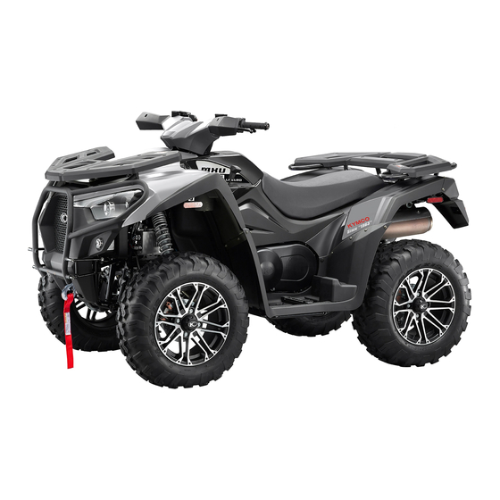
- Page 1 KYMCO Repair Manual MXU 500i/700i KYMCO MXU 700i and MXU 500i Service Information Models Covered: 2018 KYMCO MXU 700i 2018 KYMCO MXU 500i...
- Page 2 Always read a procedure in its entirety before attempting any repairs. Many thumbnail images can be clicked on to show larger images. Topics that are explained in greater detail are referenced and linked to. This manual features a 2018 KYMCO MXU 700i with a 500i engine chapter.
-
Page 3: Table Of Contents
MXU 500i/700i Quick Reference This chapter provides a quick reference source of technical specifications and information for the KYMCO MXU 700i and MXU 500i models. Break In Procedure ........................1-2 General Information ........................1-3 VIN and Engine Number Location .................... 1-24 Special Tools .......................... -
Page 4: Break In Procedure
1.Quick Reference MXU 500i/700i Break In Procedure A new ATV and an overhauled ATV engine require a "break-in" period. The first 10 hours (or 200 miles) are most critical to the life of this ATV. Proper operation during this break-in period will help assure maximum life and performance from the ATV. -
Page 5: General Information
1.Quick Reference MXU 500i/700i General Information Break In Procedure A new ATV and an overhauled ATV engine require a "break-in" period. The first 10 hours (or 200 miles) are most critical to the life of this ATV. Proper operation during this break-in period will help assure maximum life and performance from the ATV. - Page 6 1.Quick Reference MXU 500i/700i FILLING THE GAS TANK WARNING: Always fill the gas tank in a well-ventilated area Never add fuel to the ATV gas tank near any open flames or with the engine running. DO NOT SMOKE while filling the gas tank.
- Page 7 3. Either drain the gas tank or add Fuel Stabilizer to the gas in the gas tank. Remove the air filter housing cover and air filter. Start the engine and allow it to idle; then using KYMCO Engine Storage Preserver, rapidly inject the preserver into the air filter opening for a period of 10 to 20 seconds;...
- Page 8 Preparation After Storage Taking the ATV out of storage and correctly preparing it will assure many miles and hours of trouble-free riding. KYMCO recommends the following procedure to prepare the ATV. 1. Clean the ATV thoroughly. 2. Clean the engine. Remove the cloth from the muffler.
- Page 9 1.Quick Reference MXU 500i/700i 7. Tighten all nuts, bolts, cap screws, and screws making sure all calibrated nuts, cap screws, and bolts are tightened to specifications. 8. Check tire pressure, Inflate to recommended pressure as necessary. 9. Make sure the steering moves freely and does not bind. 10.Check the spark plug.
- Page 10 1.Quick Reference MXU 500i/700i When tightening bolts or nuts, begin with larger-diameter and move to smaller ones. Tighten bolts evenly and tighten to the specified torque diagonally. Use genuine parts and lubricants.
- Page 11 1.Quick Reference MXU 500i/700i When servicing the motorcycle, be sure to use the indicated special tools for removal and installation. After disassembly, clean and inspect the removed parts. Lubricate sliding surfaces with engine oil before reassembly.
- Page 12 1.Quick Reference MXU 500i/700i Apply or add designated greases and lubricants to the specified lubrication points. After reassembly, check all parts for proper tightening and operation. 1-10...
- Page 13 1.Quick Reference MXU 500i/700i When two persons work together, pay attention to the mutual working safety. Disconnect the battery negative (-) terminal before working on the vehicle. When using a spanner or other tools, make sure not to damage the motorcycle surface. 1-11...
- Page 14 1.Quick Reference MXU 500i/700i After working on the vehicle, check all connecting points, fasteners, and lines for proper connection and installation. When connecting the battery, the positive (+) terminal must be connected first. After connection, apply grease to the battery terminals. Terminal caps must be installed securely.
- Page 15 1.Quick Reference MXU 500i/700i After working on the vehicle make sure terminal caps shall have been installed securely. Disengage the lock on locking electrical connectors before attempting to unplug them. 1-13...
- Page 16 1.Quick Reference MXU 500i/700i Hold the connector body when connecting or disconnecting it. Do not pull the connector wire. Check for faulty connector terminals. There shouldn't be any bent, protruding or loose terminals. Make sure the connector is plugged in completely. Make sure the connector locks correctly if a lock is present.
- Page 17 1.Quick Reference MXU 500i/700i Before connecting an electrical connector, check for damaged terminal cover or loose negative terminal. Check the bullet connector cover for proper coverage and installation. Join the terminals completely in bullet connectors. Check the cover for proper coverage. Do not make the cover opening face up.
- Page 18 1.Quick Reference MXU 500i/700i Secure wire harnesses to the frame with the respective wire bands at the designated locations. Tighten the bands so that only the insulated surfaces contact the wire harnesses. After clamping, check each wire to make sure it is secure. 1-16...
- Page 19 1.Quick Reference MXU 500i/700i Do not squeeze wires against the weld or its clamp. After clamping, check each harness to make sure that it is not interfering with any moving or sliding parts. 1-17...
- Page 20 1.Quick Reference MXU 500i/700i Secure the wire harness so that it will not make contact with parts which will generate high heat. Route wire harnesses to avoid sharp edges or corners. Avoid the projected ends of bolts and screws. Route wire harnesses passing through the side of bolts and screws. 1-18...
- Page 21 1.Quick Reference MXU 500i/700i Route harnesses so they are neither pulled tight nor have excessive slack. Protect wires and harnesses with electrical tape or tube if they contact a sharp edge or corner. 1-19...
- Page 22 1.Quick Reference MXU 500i/700i Make sure rubber wire grommets are installed correctly. Do not break the sheath of wire. If a wire or harness has a broken sheath, repair it by wrapping it with protective tape or replace it if needed. 1-20...
- Page 23 1.Quick Reference MXU 500i/700i When installing other parts, do not press or squeeze the wires. After routing, check that the wire harnesses are not twisted or kinked. 1-21...
- Page 24 1.Quick Reference MXU 500i/700i Wire harnesses routed along with handlebar should not be pulled tight, have excessive slack or interfere with adjacent or surrounding parts in all steering positions. When a testing device is used, make sure to understand the operating methods thoroughly and operate according to the operating instructions.
- Page 25 1.Quick Reference MXU 500i/700i Be careful not to drop any parts. When rust is found on a terminal, remove the rust with sand paper or equivalent before connecting. 1-23...
-
Page 26: Vin And Engine Number Location
1.Quick Reference MXU 500i/700i VIN and Engine Number Location The VIN stamped into the front of the frame just in front of the front differential. The engine number is located near the bottom of the left crankcase half. 1-24... -
Page 27: Special Tools
1.Quick Reference MXU 500i/700i Special Tools Tool Name Tool No. Oil seal and bearing installer A120E00014 Valve adjuster A120E00080 Bearing puller A120E00037 Valve spring compressor A120E00040 Universal holder A120E00056 Drive pulley holder A120E00058 Tool Name Tool No. Clutch Spring Compressor Fittings 46mm HEX A120E00057 Flywheel puller A120E00060... -
Page 28: Specifications
1.Quick Reference MXU 500i/700i Specifications General Specifications Model No. MXU 500i LDA0CA Model No. MXU 700i LAADAA(US) Overall length 2210 mm Overall width 1220 mm Overall height 1265 mm Wheel base 1297 mm Engine type 4 stroke D.O.H.C. MXU 500i 498.5 cc Displacement MXU 700i... - Page 29 2.6 L (oil and filter change) 2.9 L (total) Air cleaner type & No Wet type element Fuel capacity 16.5 L TYPE KYMCO PTA1 Throttle body VENTURE DIA 38 mm Type Full transistor digital ignition 5° at idle rpm (MXU 500i)
- Page 30 Dual A-Arm Suspension type Rear Dual A-Arm Lubrication Specifications SERVICE ITEM STANDARD LIMIT Recommended engine KYMCO 4-stroke oil or equivalent motor oil API service — classification SJ Viscosity: SAE 5W-50 0.15 max clearance Oil pump Body 0.15 - 0.2 0.25 rotor...
- Page 31 1.Quick Reference MXU 500i/700i Lubrication type Forced pressure & Wet sump Oil pump type Trochoid Oil filter type Full-flow filtration Oil capacity MXU 500i 3.6 L Oil exchanging capacity MXU 500i 3.0 L 2.4 L (oil change) Oil capacity MXU 700i 2.6 L (oil and filter change) 2.9 L (total) Front gear box oil...
- Page 32 1.Quick Reference MXU 500i/700i Crank position sensor resistance 96 -144 Ω Standard 0.4 -1.4 V Roll sensor voltage Over 65° (fall down) 3.7- 4.4 V Engine Specifications MXU 500i Engine Item Standard mm (in) Service Limit IN 0.1 mm (0.004 in) Valve clearance (cold) EX 0.1 mm (0.004 in) Cylinder head compression pressure...
- Page 33 1.Quick Reference MXU 500i/700i Out-of-round 0.01 (0.0004) 0.1 (0.004) 0.03 - 0.065 (0.0012 - 0.0026) 0.08 (0.003) Ring-to-groove 0.065 clearance Second 0.015 - 0.05 (0.0006 - 0.002) (0.0026) 0.15 - 0.3 (0.006 - 0.012) 0.5 (0.02) Second 0.03 - 0.45 (0.012 - 0.018) 0.65 (0.026) Ring end gap Oil side...
- Page 34 1.Quick Reference MXU 500i/700i MXU700i Engine Item Standard mm (in) Service Limit IN 0.1 mm (0.004 in) Valve clearance (cold) EX 0.18 mm (0.007 in) Cylinder head compression pressure 15 kg/cm (1500 kPa, 213 psi) Cylinder head warpage 0.05 (0.002) Camshaft runout 0.05 (0.002) IN 37.9809 (1.4953)
- Page 35 1.Quick Reference MXU 500i/700i clearance 0.065 Second 0.02 - 0.06 (0.0008 - 0.0024) (0.0026) 0.25 - 0.35 (0.0098 - 0.0138) 0.5 (0.02) Second 0.7 - 0.9 (0.0276 - 0.0354) Ring end gap Oil side 0.2 - 0.7(0.008 - 0.028) 1 (0.04) rail 101.975 - 101.985 (4.0148 - Piston O.D.
- Page 36 1.Quick Reference MXU 500i/700i Cooling System Specifications ITEM SPECIFICATIONS 2.4 liter, 2.54 US qt. (MXU700i) Radiator and engine 1.95 liter, 2.06 US qt. (MXU500i) Coolant capacity Reserve tank 0.3 liter, 0.32 US qt. Radiator cap relief pressure 90 kPa (0.9 kgf/cm , 12.8 psi) Begin to open 69 - 73°C (156 - 163°F)
- Page 37 1.Quick Reference MXU 500i/700i Axial — 2 mm (0.08 in) Toe in 0~15 mm (0~0.59 in) — Item Standard mm (in) Service Limit Brake disk thickness FR: 4.0 (0.156) RR: 5.0 (0.195) FR: 3 (0.12) RR: 4 (0.156) Brake disk runout —...
- Page 38 1.Quick Reference MXU 500i/700i Stator Coil Resistance Less than 1 ohm (yellow to yellow) Peak Voltage (trigger) 7.8-9.3 volts (green/white to blue/yellow) AC Generator (no load) Output 60 AC volts @ 3000 RPM (black to black) Specifications are subject to change without notice. 1-36...
-
Page 39: Torque Specifications
1.Quick Reference MXU 500i/700i Torque Specifications Use the MXU 500i torque specs for the MXU 700i except for the specific MXU 700i Engine Torque Specs. If a specific torque spec is not given consult the General Torque Specifications. MXU500i Torque Specs Torque Item Q'ty Thread dia. - Page 40 1.Quick Reference MXU 500i/700i Tensioner sealing bolt 1 (10, 7) Rocker arm shaft 4.5 (45, 32.4) Apply oil Chain guide pivot bolt 2 (20, 15) Water joint bolt 1.2 (12, 8.6) CYLINDER: Cylinder bolt 1 (10, 7.2) DRIVE/DRIVEN PULLEY: Drive pulley nut 14 (140, 100.8) Apply oil Wet clutch nut...
- Page 41 1.Quick Reference MXU 500i/700i Front wheel hub nut 7 (70, 50) Castle nut Rear wheel hub nut 10 (100, 72) Castle nut EXHAUST MUFFLER: Exhaust muffler mounting bolt 3.5 (35, 25) Exhaust pipe mounting nut 3.5 (35, 25) Exhaust muffler band bolt 2.1 (21, 15) ENGINE ASSEMBLY: Engine mounting bolt/nut...
- Page 42 1.Quick Reference MXU 500i/700i Tie-rod lock nut 2.5 (25, 18) Steering post lower pivot 5.5 (55, 40) Bearing flange and frame 2.8 (28, 20) WHEEL: 2.8 (28, 20) Front/rear wheel and hub 6.1 (61, 44) Front wheel hub and front halfshaft(CVJ) 28 (280, 202) Castle nut Rear wheel hub and rear halfshaft(CVJ)
- Page 43 1.Quick Reference MXU 500i/700i Torque Item Thread dia. (mm) Kgf-m (N-m, ft-lb) Front caliper and knuckle 2.7 (27, 19) Rear caliper and bracket 2.7 (27, 19) Master cylinder cap screw 0.15 (1.5, 1.1) Brake caliper bleed valve 0.55 (5.5, 4.0) Brake pedal adjusting nut 0.9 (9, 6.5) Rear disc holder and gear box...
- Page 44 1.Quick Reference MXU 500i/700i NUT M8 x 1.25 24.5± 1 .2 18 APPLY OIL ROCKER COVER M6 x 1.0 SPARK PLUG M10 x 1.0 9.8-13.7 7.2-10.1 TAPPET ADJ. NUT M5 x 0.5 6.9-10.8 5.1-7.9 TENSIONER LIFTER SHF M6 x 1.0 9.8-13.7 7.2-10.1 SPECIAL SCREW SHAFT ROCKER ARM...
- Page 45 1.Quick Reference MXU 500i/700i General Torque Specifications General torque specifications are only to be used when specific torque specifications for a fastener are not provided. These specifications are for clean unlubricated threads. The size given is for thread diameter not bolt head size. Torque Item kgf-m...
-
Page 46: Troubleshooting
1.Quick Reference MXU 500i/700i Troubleshooting Engine and Fuel System Troubleshooting Problem: Engine will not start or is hard to start (Compression too low) Condition Remedy 1. Valve clearance out of adjustment 1. Adjust clearance 2. Valve guides worn 2. Replace cylinder head 3. - Page 47 1.Quick Reference MXU 500i/700i 5. ECU unit defective 5. Replace ECU Problem: Engine noisy (Excessive valve chatter) Condition Remedy 1. Valve clearance too large 1. Adjust clearance 2. Valve spring(s) weak - broken 2. Replace spring(s) 3. Rocker arm - rocker arm shaft worn 3.
- Page 48 1.Quick Reference MXU 500i/700i Condition Remedy 1. Drive or driven bevel gears damaged or worn 1. Replace gears 2. Backlash excessive 2. Adjust backlash 3. Tooth contact improper 3. Adjust contact 4. Bearing damaged 4. Replace bearing 5. Gears worn - rubbing 5.
- Page 49 1.Quick Reference MXU 500i/700i 10. Fuel pump defective 10. Replace fuel pump Problem: Exhaust smoke dirty or heavy Condition Remedy 1. Oil (in the engine) overfilled - contaminated 1. Drain excess oil - replace oil 2. Piston rings - cylinder worn 2.
- Page 50 1.Quick Reference MXU 500i/700i 8. Fan malfunctioning 8. Check fan fuse - replace fan 9. Fan switch malfunctioning 9. Replace fan switch Final Drive Troubleshooting Problem: Engine power not transmitted to wheels Condition Remedy 1. Rear axle shafts serration worn - broken 1.
- Page 51 1.Quick Reference MXU 500i/700i Problem: Spark plug electrodes overheat or burn Condition Remedy 1. Spark plug incorrect (too hot) 1. Replace plug 2. Engine overheats 2. Service cooling system 3. Spark plug loose 3. Tighten plug Problem: Magneto does not charge Condition Remedy 1.
- Page 52 1.Quick Reference MXU 500i/700i 5. Emergency stop - ignition switch off 5. Turn on switches 6. Wiring connections loose - 6. Connect - tighten - repair connections disconnected Problem: Battery "sulfation" (Acidic white powdery substance or spots on surfaces of cell plates) Condition Remedy 1.
- Page 53 1.Quick Reference MXU 500i/700i Condition Remedy 1. Connection joints loose 1. Tighten joint 2. Hose cracked 2. Replace hose 3. Piston seal worn 3. Replace brake caliper Suspension and Steering Problem: Suspension too soft Condition Remedy 1. Spring(s) weak 1. Replace spring(s) 2.
- Page 54 1.Quick Reference MXU 500i/700i 3. Tire inflation pressure low 3. Adjust pressure 4. Tie rod ends seizing 4. Replace tie rod ends 5. Linkage connections seizing 5. Repair - replace connections Problem: Steering oscillation Condition Remedy 1. Tires inflated unequally 1.
-
Page 55: Diagnostic Trouble Codes (Dtcs)
1.Quick Reference MXU 500i/700i Diagnostic Trouble Codes (DTCs) To evaluate the DTCs see the Check Engine Lamp (CELP) Diagnostic Tool topics. Failure Blinks Fault description Priority Fault management Codes 1.Stop immediately and check CELP code. 2. Check if the engine temperature Engine temperature sensor or electric circuit is faulty. - Page 56 1.Quick Reference MXU 500i/700i malfunction 1. Check if the ISC connector or wiring is faulty. Idle air valve circuit P0410 malfunction 2. Check the resistance of the idle air valve. 1.Check the ISC steps range with the diagnostic tool. Idle speed volume control P0505 2.
- Page 57 1.Quick Reference MXU 500i/700i 1. ECU output to each sensor should be 5 DCV. 2. Check if the power source for all sensors is 5 DCV. Sensor doesn't receive P1560 3. Check for a problem in the wiring power source from ECU harness.
- Page 58 Periodic Maintenance This chapter covers the location and servicing of the periodic maintenance items for the KYMCO MXU 700i and MXU 500i models. This chapter includes all information necessary to perform recommended inspections and adjustments. These preventive maintenance procedures, if followed, will ensure more reliable vehicle operation and a longer service life.
-
Page 59: Periodic Maintenance Chart
2.Periodic Maintenance MXU 500i/700i Periodic Maintenance Chart Periodic maintenance is required to keep the vehicle safe and performing properly. For use exceeding the chart repeat the service intervals. INITIAL EVERY WHICHEVER COMES FIRST 600 1200 ITEM 1000 2000 ROUTINE MONTH 1 Engine oil •Replace (Warm engine before draining). - Page 60 2.Periodic Maintenance MXU 500i/700i •Check valve clearance, Valves •Adjust if necessary. •Check operation and brake fluid. Brake •Replace brake pad if necessary. •Check coolant leakage. Coolant •Replace if necessary. •Replace coolant every 24 months. •Check operation. V-belt •Replace if damage or excessive wear. •Check leakage.
-
Page 61: Air Filter Servicing
2.Periodic Maintenance MXU 500i/700i Air Filter Servicing SAFETY FIRST: Protective gloves and eyewear are recommended at this point. Removal Cover Remove the seat. See the Seat topic for more information. The air filter housing cover is held in place by six latches. Unlock the air filter cover latches. - Page 62 2.Periodic Maintenance MXU 500i/700i Remove the air filter housing cover. Inspect the air filter housing cover rubber seal and replace it as needed. Lift out the air filter element and element holder.
- Page 63 2.Periodic Maintenance MXU 500i/700i Separate the air filter element from the holder. Loosen the air filter clamp screw with a flat blade screwdriver or an 8 mm socket. Lift out the air filter. Clean out the airbox.
- Page 64 2.Periodic Maintenance MXU 500i/700i Loosen the air filter holder screw with a #2 Phillips screwdriver. Remove the screw and washers from the air filter. Remove the air filter holders from the air filter. Slide out the air filter screen.
- Page 65 2.Periodic Maintenance MXU 500i/700i Separate the inner and outer air filter element pieces. Servicing Place the filter in a container and saturate it with a foam air filter cleaner both inside and out. Products like Simple Green, dish soap, or most non-flammable solvents will work if foam air filter cleaner is unavailable.
- Page 66 2.Periodic Maintenance MXU 500i/700i Let the filter soak for approximately 5 minutes - follow cleaning product instructions if different. Rinse the element in warm water until the water runs clear. You may squeeze the filter to remove excess cleaner but never twist it. Let the air filter dry completely.
- Page 67 2.Periodic Maintenance MXU 500i/700i Installation Install the air filter element onto the holder. Fit the air filter element and holder into place. The element holder should be on the bottom. 2-10...
- Page 68 2.Periodic Maintenance MXU 500i/700i Fit the inner air filter element into the outer element. Insert the screen into the air filter elements. 2-11...
- Page 69 2.Periodic Maintenance MXU 500i/700i Install the air filter holders into the air filter. The holders must fit together as shown. Install the air filter holder screw and washers. Tighten the air filter holder screw securely with a #2 Phillips screwdriver. 2-12...
- Page 70 2.Periodic Maintenance MXU 500i/700i Fit the air filter into place. Tighten the air filter clamp screw securely with a flat blade screwdriver or an 8 mm socket. Cover Fit the airbox cover into place. Make sure the rubber seal is installed and in good condition. 2-13...
- Page 71 2.Periodic Maintenance MXU 500i/700i Secure the air filter cover latches. Airbox Drain Inspect the airbox drain tube. 2-14...
- Page 72 2.Periodic Maintenance MXU 500i/700i Remove the tube and drain away any fluid build up or debris that has collected. Return the tube and secure it with the clamp. 2-15...
-
Page 73: Brake Fluid
MXU 500i/700i Brake Fluid The KYMCO MXU 700i models uses DOT 4 brake fluid. Do not mix the brake fluid types. The system should be bled whenever the brakes feel spongy, or if the brake system has been taken apart and rebuilt. Always use fresh brake fluid from a tightly sealed container. - Page 74 2.Periodic Maintenance MXU 500i/700i Bleeder Valves There is a bleeder valve on each brake caliper. 2-17...
- Page 75 2.Periodic Maintenance MXU 500i/700i The bleeder valves are usually very tight so use a box end wrench or a 6 point socket and ratchet to prevent rounding off the head. Snug the bleeder valve back down after breaking it loose the first time. Place the box end wrench on the valve and attach a clear hose to the bleeder valve for draining or bleeding.
- Page 76 2.Periodic Maintenance MXU 500i/700i Draining To remove the brake fluid remove the reservoir cap, open the bleeder valve and suck out he old brake fluid with a mighty-vac or similar devise. Bleeding There are three separate brake systems, one with each master cylinder. Master Cylinder Caliper/s Right Handlebar...
- Page 77 2.Periodic Maintenance MXU 500i/700i A. Remove the cover and fill the reservoir with DOT 4 brake fluid from a fresh, newly opened container and bleed the brakes. B. Install the cover to keep debris out of the fluid: then slowly compress the brake lever (or pedal) several times.
- Page 78 2.Periodic Maintenance MXU 500i/700i C. Remove the protective cap. Install one end of a clear hose onto the bleeder screw of the brake system being serviced, and direct the other end into a container: then while holding pressure on the brake lever, open the bleeder screw and watch for air bubbles. Close the bleeder screw before releasing the brake lever.
-
Page 79: Brake Inspection
2.Periodic Maintenance MXU 500i/700i Brake Inspection SAFETY FIRST: Protective gloves and eyewear are recommended at this point. Master Cylinder Place the vehicle on level ground so the master cylinder reservoirs are level. Check the level of brake fluid. The brake fluid level should be above the "L" line. Remove the rear fender to view the rear brake master cylinder reservoir. - Page 80 2.Periodic Maintenance MXU 500i/700i Note: The more the brake pads are worn the more fluid will be required from the reservoir to fill out the system. If the brake fluid is filled with worn pads, and new pads are installed the brake fluid level in the reservoir will rise.
- Page 81 2.Periodic Maintenance MXU 500i/700i Brake Discs Inspect the brake disc for damage. See the Brake Discs topic for more information. Rear Brake Pedal Height Remove the right mudguard. See the Mudguards and Footrests topic for more information. To adjust the rear brake pedal height loosen the locknut and turn the adjuster bolt. Tighten the locknut securely when finished.
- Page 82 2.Periodic Maintenance MXU 500i/700i Rear Brake Light Switch The rear brake light switch should trigger the brake light just before the rear brake engages. Hold the switch body still and turn the nut to adjust the rear brake light switch if needed. 2-25...
-
Page 83: Compression Check
2.Periodic Maintenance MXU 500i/700i Compression Check SAFETY FIRST: Protective gloves and eyewear are recommended at this point. Run the engine to warm it up before conducting a compression test. Make sure your compression gauge is in good working order and does not leak. The battery must be fully charged when testing the compression. - Page 84 2.Periodic Maintenance MXU 500i/700i Hold the throttle wide open and use the electric starter to turn the engine over. Crank the engine until the needle on your compression gauge stops rising. This should occur in 4 to 7 seconds of engine cranking. Do not crank the engine for more than 7 seconds. Compare your reading with the specification.
-
Page 85: Engine Idle Speed
2.Periodic Maintenance MXU 500i/700i Engine Idle Speed SAFETY FIRST: Protective gloves and eyewear are recommended at this point. Start the engine and let it warm up. The engine must reach 80° C to correctly inspect the idle speed. Connect the diagnostic tool and use the DATA analyze feature to inspect the idle speed. See the Diagnostic Tool topic for more information. -
Page 86: Engine Oil
SERVICE ITEM STANDARD LIMIT Recommended KYMCO 4-stroke oil or equivalent motor oil API service — engine oil classification SJ Viscosity: SAE 5W-50 Other engine oil viscosities shown in the chart may be used when the average temperature in the riding area is within the indicated range. - Page 87 2.Periodic Maintenance MXU 500i/700i Inspection Start the engine and let it warm up for 2 - 3 minutes. Park the vehicle on a level surface. Stop the engine and allow the oil to settle for at least a minute. The oil sight glass is located on the right side of the vehicle. Peak behind the footrest mudguard to see the oil sight glass and oil filler cap.
- Page 88 2.Periodic Maintenance MXU 500i/700i Inspect the oil level through the sight glass. The sight glass is located on the left side of the engine. The oil level should be between the "H" and "L" marks as shown. If the oil level is at or below the "L" mark add more of the same type and brand of oil to the engine through the oil filler hole.
- Page 89 2.Periodic Maintenance MXU 500i/700i Servicing To replace the oil filter cartridge remove the right side cover. See the Side Covers topic for more information. Start and run the engine for a minute or two, this will heat the engine and allow the oil to drain out faster and more completely.
- Page 90 2.Periodic Maintenance MXU 500i/700i Loosen the oil filter cap with a 19 mm socket. Remove the drain plug, oil filter cap, strainer, spring and O-ring. Allow the oil to drain into the pan. Clean and inspect the strainer. Inspect the O-ring. Replace any parts if needed. Note: You can remove the drain plug to drain the engine oil also, but you will not be able to clean the strainer.
- Page 91 2.Periodic Maintenance MXU 500i/700i Remove the oil cap for faster draining. Use an oil filter wrench and loosen the oil filter cartridge. Special Tool - Oil Filter Wrench: A120E00052 2-34...
- Page 92 2.Periodic Maintenance MXU 500i/700i Remove the oil filter cartridge. Apply engine oil to the O-ring. When the oil has finished draining install the oil filter cap, strainer, spring and O-ring. Torque the oil filter cap to specification with a 17 mm socket. Torque Item Q'ty Thread dia.
- Page 93 2.Periodic Maintenance MXU 500i/700i Apply fresh engine oil to the rubber oil filter cartridge seal. Install the oil filter cartridge onto the engine and tighten by hand until the oil filter contacts the engine. 2-36...
- Page 94 2.Periodic Maintenance MXU 500i/700i Tighten the oil filter cartridge to specification with the oil filter wrench. Torque Item Q'ty Thread dia. (mm) Remarks kgf-m (N-m, ft-lb) Engine oil filter cartridge 1 (10, 7.2) Apply oil Refilling Oil total capacity MXU 500i 3.6 L Oil exchanging capacity MXU 500i 3.0 L...
- Page 95 2.Periodic Maintenance MXU 500i/700i Add the proper type and quantity of oil and install the oil filler cap. Start the engine and let it run for several minutes. Check for any oil leaks. Check the oil level as describe above. If the oil level is too high drain the excess oil from the oil drain bolt.
-
Page 96: Final Drive Oil
2.Periodic Maintenance MXU 500i/700i Final Drive Oil SAFETY FIRST: Protective gloves and eyewear are recommended at this point. Front gear box oil Recommended oil: SAE 80 At disassembly: 270 cc At change: 250 cc Rear gear box oil Recommended oil: SAE 80 At disassembly: 250 cc... - Page 97 2.Periodic Maintenance MXU 500i/700i Remove the oil level check bolt with an 8 mm socket. If oil doesn't flow from the check hole add oil until it reaches the level of the check hole. Return the check bolt to the hole and tighten it securely with an 8 mm socket.
- Page 98 2.Periodic Maintenance MXU 500i/700i The drain bolt (D) is located on the right side of the front final drive gear case. Place a suitable oil drain pan under the drain bolt. Remove the drain bolt with an 8 mm socket. Allow the gear oil to drain into the drain pan. Install the drain plug and tighten it to specification with an 8 mm socket.
- Page 99 2.Periodic Maintenance MXU 500i/700i Filling Front gear box oil Recommended oil: SAE 80 At disassembly: 270 cc At change: 250 cc Remove the filler cap with a 17 mm socket. Inspect the filler cap O-ring and replace it as needed. Remove the check level bolt.
- Page 100 2.Periodic Maintenance MXU 500i/700i Install the check bolt and filler cap and tighten them to specification. Torque Item Q'ty Thread dia. (mm) Kgf-m (N-m, ft-lb) Front drive gear oil filler cap 3.5 (35 25.5) Front drive gear oil level check bolt 1 (10, 7.2) 2-43...
- Page 101 2.Periodic Maintenance MXU 500i/700i Rear Final Drive Gear Oil Inspection The filler cap (F), check bolt (C), and drain bolt (D) are all located on the left side of the rear final drive gear case. Remove the oil level check bolt with a 12 mm socket. If oil doesn't flow from the check hole add oil until it reaches the level of the check hole.
- Page 102 2.Periodic Maintenance MXU 500i/700i Draining Remove the filler cap with a 17 mm socket. Inspect the filler cap O-ring and replace it as needed. 2-45...
- Page 103 2.Periodic Maintenance MXU 500i/700i Place a suitable oil drain pan under the drain bolt. Remove the drain bolt. Allow the gear oil to drain into the drain pan. Install the drain plug and tighten it to specification. Torque Item Q'ty Thread dia. (mm) Kgf-m (N-m, ft-lb) Rear drive gear oil drain bolt 2 (20, 15)
- Page 104 2.Periodic Maintenance MXU 500i/700i Inspect the filler cap O-ring and replace it as needed. Remove the check level bolt. Fill the gear oil until the oil level reaches the check bolt hole. Recommended oil: SAE 80 At disassembly: 250 cc At change: 230 cc 2-47...
- Page 105 2.Periodic Maintenance MXU 500i/700i Install the filler cap and tighten it securely with a 17 mm socket. Torque Item Q'ty Thread dia. (mm) Kgf-m (N-m, ft-lb) Rear drive gear oil filler cap 1.5 (15, 11) 2-48...
-
Page 106: Spark Arrestor
2.Periodic Maintenance MXU 500i/700i Spark Arrestor SAFETY FIRST: Protective gloves and eyewear are recommended at this point. Removal Note: Always allow the exhaust system plenty of time to cool before touching it. 2-49... - Page 107 2.Periodic Maintenance MXU 500i/700i Remove the three spark arrestor bolts with an 8 mm socket. Remove the spark arrestor and gasket. 2-50...
- Page 108 2.Periodic Maintenance MXU 500i/700i Clean the carbon off of the spark arrestor screen with a wire brush. Inspect the spark arrestor screen for any damage and replace as needed. Installation Install the spark arrestor with a new gasket. 2-51...
- Page 109 2.Periodic Maintenance MXU 500i/700i Install the spark arrestor bolts and tighten them securely with an 8 mm socket. 2-52...
-
Page 110: Spark Plug
2.Periodic Maintenance MXU 500i/700i Spark Plug SAFETY FIRST: Protective gloves and eyewear are recommended at this point. Spark plug NGK-CR7E Spark plug gap 0.6 - 0.7 mm (0.024 - 0.028 in.) Removal Remove these components Component Topic Seat Seat Fuel tank and shield Fuel Tank Pull the spark plug cap off of the spark plug. - Page 111 2.Periodic Maintenance MXU 500i/700i Clean off the area surrounding with compressed air or a shop towel to make sure debris doesn't get into the combustion chamber when the spark plug is removed. NOTE: Always wear safety glasses when using compressed air and never point it directly at yourself or anyone else.
- Page 112 2.Periodic Maintenance MXU 500i/700i Inspection Inspect the spark plug for signs of damage. Always replace a spark plug if any part of it is damaged. The color of the spark plug's porcelain tip can indicate how the mixture is burning. A white colored plug shows a lean mixture, where a dark plug shows a rich mixture.
- Page 113 2.Periodic Maintenance MXU 500i/700i If the plug is dirty or has carbon build up it can be cleaned with small wire brush. Do not hesitate to replace a spark plug. Always check the gap of the spark plugs before installation. If the gap needs to be adjusted bend the ground electrode carefully.
- Page 114 2.Periodic Maintenance MXU 500i/700i Installation Install the spark plug by hand. Tighten it to specification a 5/8 in deep well spark plug socket. TORQUE ITEM THREAD SIZE AND TYPE kgf-m ft-lb SPARK PLUG M10 X 1.0 9.8-13.7 1.0-1.4 2-57...
- Page 115 2.Periodic Maintenance MXU 500i/700i Do not over tighten the spark plug. The cylinder head is made out of soft metal, and it can be easily damaged. Install the spark plug cap onto the spark plug. Install these components Component Topic Fuel tank and shield Fuel Tank Seat...
-
Page 116: Throttle Free Play
2.Periodic Maintenance MXU 500i/700i Throttle Free Play SAFETY FIRST: Protective gloves and eyewear are recommended at this point. Inspection Inspect the throttle free play by operating the throttle lever. The free play should be 3 - 5 mm (0.125 - 0.20 in) measured at the end of the throttle lever. The free play is the distance from the lever at rest to where resistance is felt. - Page 117 2.Periodic Maintenance MXU 500i/700i To adjust the throttle free play loosen the knurled lock nut on the throttle cable. Turn the adjuster out to decrease free-play and turn it in to increase free-play. 2-60...
- Page 118 2.Periodic Maintenance MXU 500i/700i Always check that the throttle operates freely and returns properly. Tighten the knurled lock nut securely. Slide the rubber cover into place. 2-61...
- Page 119 2.Periodic Maintenance MXU 500i/700i Throttle Limiter The throttle limiter can be used to adjust how much the throttle can be open. Loosen the locknut and turn the screw to adjust the throttle. Do not adjust the screw so that it is more than 13 mm out from the housing.
-
Page 120: Tires
2.Periodic Maintenance MXU 500i/700i Tires SAFETY FIRST: Protective gloves and eyewear are recommended at this point. Tire Size Front wheel AT 25 X 8-12 Tires (standard models) Rear wheel AT 25 X 10-12 Front wheel AT 26 X 9-14 Tires (LE models) Rear wheel AT 26 X 11-14 2-63... - Page 121 2.Periodic Maintenance MXU 500i/700i Air Pressure Check the tire pressure with a low pressure gauge. Front (standard) 0.35 kgf/cm (35 Kpa, 5.0 psi) Rear (standard) 0.32 kgf/cm (32Kpa, 4.5 psi) Tire pressure Front (LE) 0.7 kgf/cm (70 Kpa, 10 psi) Rear (LE) 0.97 kgf/cm (97 Kpa, 14 psi)
- Page 122 2.Periodic Maintenance MXU 500i/700i Tire Tread Depth Check that the tire tread depth is within specification. Tire Tread Depth Service Limit Front Tire 4 mm (0.16 in) Rear Tire 4 mm (0.16 in) Directional Rotation Check the "ROTATION" arrow on the tire's sidewall.The arrow indicates the direction in which the tire should turn going forward.
-
Page 123: Suspension And Steering Inspection
2.Periodic Maintenance MXU 500i/700i Suspension and Steering Inspection SAFETY FIRST: Protective gloves and eyewear are recommended at this point. Place the machine on a level place. Check the steering column bushings and bearings: Move the handlebar up and down, and/or back and forth. Replace the steering column bushings and or bearings if excessive play. - Page 124 2.Periodic Maintenance MXU 500i/700i Replace the tie-rod ends if tie-rod end has any vertical play. See the Tie-Rods topic for more information. Raise the front end of the machine so that there is no weight on the front wheels. Check ball joints and/or wheel bearings.
- Page 125 2.Periodic Maintenance MXU 500i/700i Replace the front arms and/or wheel bearings if there excessive free play. See the A-arms Steering Knuckles topics for more information. Inspect the rear suspension in the same manner. See the Rear Suspension chapter for more information. 2-68...
- Page 126 2.Periodic Maintenance MXU 500i/700i Pre-load The shock absorbers have adjustable preload collars. Turn the preload collar with a pin spanner to adjust the spring preload. Increase the amount or preload for heavy loads. Note: Always adjust both front shock absorber spring pre-load to the same setting. Uneven adjustment can cause poor handling and loss of stability.
- Page 127 2.Periodic Maintenance MXU 500i/700i Standard position: 2 Minimum (Soft) position: 1 Maximum (Hard) position: 5 Toe-in Check Make sure the vehicle is clean and mud free. Position the vehicle on a level surface at its operating weight without a rider. Check that all tires are properly inflated at the same pressure.
- Page 128 2.Periodic Maintenance MXU 500i/700i Raise the front tires off the ground. Straighten the front wheels on a level surface. The handlebar must be positioned straight ahead. Measure the handlebar position on each side to confirm this. Do not change the handlebar position from straight ahead.
- Page 129 2.Periodic Maintenance MXU 500i/700i Adjustment Mark the tie-rods for reference. The outer tie-rod locknuts have reverse threads. Loosen the tie-rod locknuts with a 19 mm wrench. 2-72...
- Page 130 2.Periodic Maintenance MXU 500i/700i Turn the tie-rod flats with a 17 mm wrench. Turn the tie rods evenly until till the toe-in is within specification. Moving the tie-rods out towards the wheels will narrow the distance between the front of the tires. Moving the tie-rods towards the center will increase the distance between the front of the tires.
- Page 131 2.Periodic Maintenance MXU 500i/700i Tighten the tie-rod locknuts to specification with a 19 mm wrench. Torque Item Q'ty Thread dia. (mm) Kgf-m (N-m, ft-lb) Tie-rod adjusting nut 3.5 (35, 25.5) After adjusting the toe-in take the machine for a slow test ride. If the machine pulls to the left or right when the steering wheel is facing straight ahead the toe-in needs to be readjusted more evenly.
-
Page 132: Valve Clearance
2.Periodic Maintenance MXU 500i/700i Valve Clearance SAFETY FIRST: Protective gloves and eyewear are recommended at this point. MXU 700i Inspection The engine has to be cold (room temperature) to check the valve clearance. Remove these components Component Topic Seat Seat Fuel tank and shield Fuel Tank Side covers... - Page 133 2.Periodic Maintenance MXU 500i/700i Inspect the O-ring and replace it as needed. The valve adjuster covers are each held on with three bolts. 2-76...
- Page 134 2.Periodic Maintenance MXU 500i/700i Remove the valve adjuster cover bolts with an 8 mm socket. Lift off the valve adjuster covers. 2-77...
- Page 135 2.Periodic Maintenance MXU 500i/700i Inspect the valve adjuster cover O-rings and replace them as needed. The piston should be at TDC (Top Dead Center) on the compression stroke to check the valve clearance. Turn the crankshaft clockwise with a 19 mm socket. Observe the movement of the intake valves and check the position of the flywheel through the timing hole.
- Page 136 2.Periodic Maintenance MXU 500i/700i The intake valves should open and close. Align the "T" mark on the flywheel with the index mark on the crankcase cover. This shows the piston is at Top Dead Center (TDC). 2-79...
- Page 137 2.Periodic Maintenance MXU 500i/700i The piston should now be at TDC (Top Dead Center) on the compression stroke. You can make sure that it is on the compression stroke by checking that there is some slack in the rocker arms. If the rocker arms are rigid, rotate the crankshaft 360° until the "T" mark is once again aligned with the notch on the case cover.
- Page 138 2.Periodic Maintenance MXU 500i/700i Adjustment Use a valve adjuster tool to adjust the valves. Special Tool- Valve Adjuster: A120E00080 Loosen the valve adjuster locknut with a wrench. Use the valve adjuster tool to turn the adjuster in or out. 2-81...
- Page 139 2.Periodic Maintenance MXU 500i/700i If the valve clearance is too tight back out the valve adjusting screw with the valve adjustment tool. If the clearance is too loose turn in the valve adjusting screw until there is a light drag on the feeler gauge. Hold the adjusting screw locknut in place with the wrench to make sure it doesn't interfere with the adjustment.
- Page 140 2.Periodic Maintenance MXU 500i/700i Install the valve adjuster cover bolts. Tighten the bolts securely with an 8 mm socket. Make sure the crankshaft cap O-ring is in good condition. Apply fresh engine oil to the O-ring. 2-83...
- Page 141 2.Periodic Maintenance MXU 500i/700i Install the crankshaft cap. Tighten the crankshaft cap securely with a 10 mm Allen socket. Do not over tighten this cap. 2-84...
- Page 142 2.Periodic Maintenance MXU 500i/700i Make sure the timing plug O-ring is in good condition. Apply fresh engine oil to the O-ring. Install the timing inspection plug and tighten it securely with a large flat blade screwdriver. Install these components Component Topic Spark plug Spark Plug...
- Page 143 2.Periodic Maintenance MXU 500i/700i MXU 500i Inspection Remove these components Component Topic Seat Seat Fuel tank and shield Fuel Tank Side covers Side Covers Right mudguard Mudguards and Footrests Recoil starter cover Recoil Starter Cover Spark plug Spark Plug Cylinder head cover Cylinder Head Cover Remove the timing cap on the right side of the engine with a flat blade screwdriver.
- Page 144 2.Periodic Maintenance MXU 500i/700i Align the "T" mark on the flywheel with the index mark on the right crankcase cover. This shows the piston is at Top Dead Center (TDC). Make sure the punch marks on the ends of the camshafts are pointed up. With the marks pointing up the piston is at TDC on the compression stroke.
- Page 145 2.Periodic Maintenance MXU 500i/700i Measure the valve clearance with a thickness feeler gauge. Insert the feeler gauge between the adjusting screw and the valve stem. The clearance is correct when there is a light drag on the feeler gauge. If the clearance is out of spec move on to the adjustment section.
- Page 146 2.Periodic Maintenance MXU 500i/700i If the valve clearance is too tight, back out the valve adjusting screw with the valve adjustment tool. If the clearance is too loose, turn in the valve adjusting screw until there is a light drag on the feeler gauge. Hold the adjusting screw locknut in place with the wrench to make sure it doesn't interfere with the adjustment.
- Page 147 3.Fuel System MXU 500i/700i Fuel System MXU 700i This chapter covers the location and servicing of the fuel system components for the fuel injected KYMCO MXU 700i models. Airbox ..........................3-4 Check Engine Lamp (CELP) ..................3-9 Component Location ....................3-13 Diagnostic Tool ......................3-18...
- Page 148 3.Fuel System MXU 500i/700i ● Work in a fully ventilated area. Smoking or allowing flames or sparks in the work area or where gasoline is stored can cause a fire or explosion. ● Do not apply carburetor cleaners to the inside of the throttle body. ●...
- Page 149 3.Fuel System MXU 500i/700i TROUBLESHOOTING Engine fail to start • Battery voltage too low • Fuel level too low • Pinched or clogged fuel hose • Faulty fuel pump operating system • Clogged fuel injector • Faulty spark plug or wrong type •...
-
Page 150: Airbox
3.Fuel System MXU 500i/700i Airbox SAFETY FIRST: Protective gloves and eyewear are recommended at this point. Removal Remove the air filter. See the Air Filter Servicing topic for more information. Squeeze the breather hose clip and slide it back. Free the breather hose from the airbox boot. - Page 151 3.Fuel System MXU 500i/700i Loosen the throttle body to airbox clamp with a #2 Phillips screwdriver. Free the airbox from the throttle body. Remove the airbox. Cover the mouth of the throttle body with a clean shop towel or tape to prevent debris from entering the engine.
- Page 152 3.Fuel System MXU 500i/700i Installation Fit the airbox into place. Connect the airbox to the throttle body.
- Page 153 3.Fuel System MXU 500i/700i Install the bracket and two airbox bolts. Tighten the airbox bolts securely. Tighten the airbox to throttle body clams securely with a #2 Phillips screwdriver.
- Page 154 3.Fuel System MXU 500i/700i Connect the breather hose to the airbox boot. Secure the hose with the clamp. Install the air filter. See the Air Filter Servicing topic for more information.
-
Page 155: Check Engine Lamp (Celp)
3.Fuel System MXU 500i/700i Check Engine Lamp (CELP) SAFETY FIRST: Protective gloves and eyewear are recommended at this point. Display Indicators Note: The check engine lamp (CELP) will come on for 2 seconds when the key is turned on. It should go off when the engine is started. If it lights after this the system has detected a problem. - Page 156 3.Fuel System MXU 500i/700i The wrench icon on the display will come on when the key is turned on and go away when the engine has started. If the wrench icon come on the this indicates and EFI system electric part fault and and a failure code is present. Failure Code Indicator If the ECU connectors, or battery leads are disconnected the stored malfunction codes will be lost.
- Page 157 3.Fuel System MXU 500i/700i Without Diagnostic Special Tool SELF-DIAGNOSTIC PROCEDURES ● Turn key to the ON position. ● The CELP will light for two seconds and then go off. ● If the engine has problem, the CELP will blink to show the failure codes. ●...
- Page 158 3.Fuel System MXU 500i/700i In this example the failure codes corresponding with 21 and 22 blinks need to be evaluated. To see the full list of trouble codes see the Diagnostic Trouble Codes (DTCs) topic. With Special Tool See the Fuel Injection Diagnostic Tool topic.
-
Page 159: Component Location
3.Fuel System MXU 500i/700i Component Location SAFETY FIRST: Protective gloves and eyewear are recommended at this point. Right Side Regulator/Rectifier Gear Position Switch Winch Leads Stator Coil and Ignition Pulse Generator / Crank Position Sensor 3-13... - Page 160 3.Fuel System MXU 500i/700i Left Side and Center Roll Sensor (Tip-over Switch) Diagnostic Tool Connector Throttle Body Ignition Coil Spark Plug Water Temperature Sensor 3-14...
- Page 161 3.Fuel System MXU 500i/700i Throttle Body The following components can be found here. Throttle Body • T-MAP (Manifold Air Pressure) • Fuel Injector • Fuel Hose • TPS (Throttle Position Sensor) • ISC (Idle Speed Control) • 3-15...
- Page 162 3.Fuel System MXU 500i/700i Under The Seat Winch Leads (optional) Battery Relays (see below) Starter Relay Fuse Box 3-16...
- Page 163 3.Fuel System MXU 500i/700i Relays Fan Relay Engine Start Relay Fuel Pump Relay Switched Power Relay Fuel Pump The fuel pump is located inside the fuel tank. 3-17...
-
Page 164: Diagnostic Tool
Diagnostic tool Part Number: 3620A-LEB2-E00 CAN Linker Part Number: 3620A-LGC7-E000 This tool has been developed by KYMCO and for KYMCO vehicles only. The tool software can be updated for new models with a computer via the USB cable. Please refer to the specifications when servicing this vehicle. See the... - Page 165 3.Fuel System MXU 500i/700i Plug the diagnostic tool connector into the CAN Linker as shown. Remove the front cover to access the diagnostic tool connector. See the Front Cover topic for more information. 3-19...
- Page 166 3.Fuel System MXU 500i/700i Remove the dummy side of the connector. Set a multimeter to reads voltage (DCV). Measure the voltage as indicated. Terminal (+) Terminal (-) Normal BR/L Battery Voltage Battery Voltage - 1 Connect the CAN Linker to the diagnostic plug. Turn on the ignition switch to send power to the tool.
- Page 167 3.Fuel System MXU 500i/700i The functions of the diagnostic tool include ECU version, model name, data analysis and adjust. ECU version: includes model name, ECU number, identifications number and software version. DTC Inspect: DTC reading, DTC clearing, and troubleshooting. Data Analyze: For ECU’s setting inspection and running condition analysis. Adjust: Not allowed ECU Version The four functions will display when the tool is powered on.
- Page 168 3.Fuel System MXU 500i/700i Pressing the enter button on the ECU version will show information on the ECU software and calibration. Press the down button (right) to return to the first page. DTC (Diagnostic Trouble Code) INSPECTION PROCEDURE Press the down button (right) to move the item selector down to the DTC Inspect item. 3-22...
- Page 169 3.Fuel System MXU 500i/700i Pressing the enter button on the DTC Inspect item will bring up the options shown above. Select the DTC Load option and press the enter button to display the DTC options. There are three DTC options - Active, Occurred, and History. Move the selector to the Active option and press enter to display current DTC.
- Page 170 3.Fuel System MXU 500i/700i The diagnostic tool will display all current DTC. In the photo above only one code (12) is showing. Select the code number of interest and press enter for more information on that DTC. In this instance the indicated code is 12 (CELP blinks). This corresponds to the DTC P0230.
- Page 171 3.Fuel System MXU 500i/700i Failure Blinks Fault description Priority Fault management Codes 1. Make sure the relay connector is connected correctly. Fuel pump relay or electric 2. Check if the ECU sends a signal to P0230 circuit malfunction relay. 3. Check the fuel pump relay resistance Consult the DTC table for more information on how to troubleshoot the problem.
- Page 172 3.Fuel System MXU 500i/700i Pressing the enter button on the DTC Inspect item will bring up the options shown above. Move the selector down to the Clear DTC option and press enter. The diagnostic tool will show when the DTC in memory is cleared. Also, the DTC indicator light will be off.
- Page 173 3.Fuel System MXU 500i/700i Data Analysis Procedure When using the data analysis feature for running condition items such as ignition advance, ISC step, ect., make sure the engine temperature has reached 80° C. The engine temperature is displayed on data analysis page 03. Press the down button (right) to move the item selector down to the DATA Analyze item.
- Page 174 3.Fuel System MXU 500i/700i Page 02 The 02 page shows TPS position and TPI idle adapted. Page 03 The 03 page shows engine temperature, air temperature, and intake pressure. 3-28...
- Page 175 3.Fuel System MXU 500i/700i Page 04 The 04 page shows atmospheric pressure, fuel injection interval, and ignition advance. Page 05 The 05 page shows the rollover voltage. 3-29...
- Page 176 3.Fuel System MXU 500i/700i Page 06 The 06 page shows the ISC step and ISC learn step. Page 07 The 07 page shows the ECU counter. 3-30...
-
Page 177: Fuel Injection Sensors
3.Fuel System MXU 500i/700i Fuel Injection Sensors SAFETY FIRST: Protective gloves and eyewear are recommended at this point. You will need a digital multimeter to inspect the sensors. Water Temperature Sensor (WTS) Removal Remove the left side cover. See the Side Covers topic for more information. - Page 178 3.Fuel System MXU 500i/700i Push in the spring and unplug the WTS sensor connector. Remove the sensor with a 22 mm wench. 3-32...
- Page 179 3.Fuel System MXU 500i/700i Installation Thread in the WTS. Tighten the WTS to specification with a deep well 22 mm socket. ITEM kgf-m ft-lb Inspection Input Voltage Turn the ignition switch to the OFF position. 3-33...
- Page 180 3.Fuel System MXU 500i/700i Push in the spring and unplug the WTS sensor connector. Set the multimeter to read voltage (DCV). Turn the ignition switch to the ON position. Measure the input voltage on the harness side of the connector. (WTS Input Voltage: 5 ±...
- Page 181 3.Fuel System MXU 500i/700i Suspend the sensor and a thermometer in a pot of coolant with string. Make sure the WTS and the thermometer are not touching the pot. Bring the temperature up to the specification slowly and check the resistance between the sensor terminal and body. Temperature Standard Resistance (approximate) 60°...
- Page 182 3.Fuel System MXU 500i/700i Manifold Air Temperature Pressure (T-MAP) To remove and install the sensors on the throttle body see the Throttle Body Components topic. Input Voltage Inspection Turn the ignition switch to the OFF position. Unplug the T-MAP connector. Set the multimeter to read voltage (DCV).
- Page 183 3.Fuel System MXU 500i/700i Resistance Set the multimeter to ohms of resistance (kΩ). Measure the resistance between the 3 and 4 pins of the T-MAP sensor. ITEM SPECIFICATION T-MAP sensor resistance (20°C) 1613 - 2544 Ω To replace the T-MAP sensor see the Throttle Body Components topic.
- Page 184 3.Fuel System MXU 500i/700i Measure if the ECU voltage outputs to TPS between the following terminals of the TPS connector. Terminal Normal Violet/Red (+) – Violet/Green (-) Resistance Inspection Set the multimeter to ohms of resistance (kΩ). Measure the resistance between the ground (A) and input (C) terminals of the TPS. Throttle Position Sensor (TPS) 3500 - 6500 Ω...
- Page 185 3.Fuel System MXU 500i/700i Throttle Position Opening Angle Standard Close 0.67 ± 0.05 V Open > 90 % 1.8 - 2.3 V To replace the TPS see the Throttle Body Components topic. Crankshaft Position Sensor (CKP) See the ignition pulse generator in the Generator Cover topic.
- Page 186 3.Fuel System MXU 500i/700i Remove the two roll sensor screws with a #2 Phillips screwdriver. Unplug the roll sensor and remove it. Plug in the roll sensor and install it so the UP mark faces up. Tighten the two roll sensor screws securely with a #2 Phillips screwdriver.
- Page 187 3.Fuel System MXU 500i/700i Inspection Turn the ignition switch to the OFF position. Remove the roll sensor screws, but leave the sensor plugged in. Set the multimeter to read voltage (DCV). Turn the ignition switch to the ON position. Measure the voltage of the roll sensor wires with the connector plugged in and the sensor in the regular upright attitude.
- Page 188 3.Fuel System MXU 500i/700i Incline the roll sensor 65 ± 10 degrees to the left or right. Check the voltage. Terminal Normal Violet/Red (+) - Green (-) 5 V (ECU Voltage) Black/White (+) - Green (-) 0.4 - 1.4 V If this test is to be repeated the ignition switch must be turned OFF to reset the system.
-
Page 189: Fuel Injector
3.Fuel System MXU 500i/700i Fuel Injector SAFETY FIRST: Protective gloves and eyewear are recommended at this point. Warning: Gas is extremely flammable! Do not work around an open flame or a source of sparks. Removal Remove these components Component Topic Seat Seat Side covers... - Page 190 3.Fuel System MXU 500i/700i Push in the spring clip and unplug the fuel injector connector. 3-44...
- Page 191 3.Fuel System MXU 500i/700i Disassembly MXU500i Remove the two fuel injector mounting bolts with a 10 mm socket. Remove the fuel injector and pipe from the intake pipe. 3-45...
- Page 192 3.Fuel System MXU 500i/700i Slide off the clip and pull the fuel injector out of its pipe. The O-rings should be replaced with new items on installation. 3-46...
- Page 193 3.Fuel System MXU 500i/700i MXU700i On the MXU 700i models remove the single bolt with an 8 mm socket. Remove the fuel injector and pipe from the intake pipe. 3-47...
- Page 194 3.Fuel System MXU 500i/700i Slide off the clip and pull the fuel injector out of its pipe. The O-rings should be replaced with new items on installation. 3-48...
- Page 195 3.Fuel System MXU 500i/700i Inspection A digital multimeter is needed to test the fuel injector. Set the multimeter to read ohms of resistance (Ω). Measure the resistance between the fuel injector terminals ITEM SPECIFICATIONS Fuel injector resistance (at 20°C/68°F) 10.6 - 15.9 Ω Cleaning PROBLEM 1.
- Page 196 3.Fuel System MXU 500i/700i SOLUTION 1. Use the specified injector cleaner. 2. Connect the battery as pictured. 3. The injector cleaner with the flash relay. 4. Keeping the fuel injector operating. 5. Wait for 20-30 minutes. 6. Clean the carbons completely from the injector. 3-50...
- Page 197 3.Fuel System MXU 500i/700i Assembly MXU500i Install new O-rings to the fuel injector. Apply a light coat of fresh engine oil to the fuel injector O-ring seals. Install the fuel injector into the pipe. Install the clip to secure the fuel injector. 3-51...
- Page 198 3.Fuel System MXU 500i/700i Install fuel injector and pipe onto the intake pipe. Guide the fuel injector into place, and be sure not to damage the O-ring. Install the two fuel injector mounting bolts and tighten them securely. 3-52...
- Page 199 3.Fuel System MXU 500i/700i MXU700i Install the fuel injector into the pipe. Install the clip to secure the fuel injector. 3-53...
- Page 200 3.Fuel System MXU 500i/700i Install fuel injector and pipe onto the intake pipe. Guide the fuel injector into place, and be sure not to damage the O-ring. Fit the post on the fuel pipe into the slot on the intake manifold. Install the bolt and tighten it securely with an 8 mm socket.
- Page 201 3.Fuel System MXU 500i/700i Installation Plug in the fuel injector connector. Connect the fuel hose to the fuel injector pipe. Tighten the fuel hose clamp securely with a #2 Phillips screwdriver. Install these components Component Topic Fuel tank and shield Fuel Tank Side covers Side Covers...
-
Page 202: Fuel Pump
3.Fuel System MXU 500i/700i Fuel Pump SAFETY FIRST: Protective gloves and eyewear are recommended at this point. Warning: Gas is extremely flammable! Do not work around an open flame or a source of sparks. Fuel Line Inspection Remove the seat. See the Seat topic for more information. - Page 203 3.Fuel System MXU 500i/700i Unplug the fuel pump connecter. Set the multimeter to read voltage (DCV). Touch the multimeter leads to the harness side of the fuel pump connector, with the positive lead touching the orange/red wire terminal and the negative lead touching the green wire terminal.
- Page 204 3.Fuel System MXU 500i/700i Clean the disconnect fitting and put a rag over it. Push down on the black release and disconnect the fuel fitting from the fuel tank. Place plastic bags over the fuel line ends to keep debris out and prevent damage. Remove the six fuel pump bolts with a 10 mm socket.
- Page 205 3.Fuel System MXU 500i/700i Remove the fuel pump mounting ring. Note the position of the fuel pump outlet pipe. Mark the fuel tank with the outlet pipe position so the fuel pump can be installed to the correct position. 3-59...
- Page 206 3.Fuel System MXU 500i/700i Carefully lift out the fuel pump. Guide the fuel level float out of the fuel tank with the pump. Remove the O-ring from the fuel pump. Discard the fuel pump O-ring, and replace it with a new item on assembly.
- Page 207 3.Fuel System MXU 500i/700i Inspect the fuel filter and replace it as needed. 3-61...
- Page 208 3.Fuel System MXU 500i/700i Fuel Level Gauge Inspection Make sure the fuel level gauge float arm moves smoothly. Using a digital multimeter set to ohms of resistance (Ω). Measure the resistance between the gray wire fuel pump/level gauge connector terminals with the float raised to the positions indicted below. 3-62...
- Page 209 3.Fuel System MXU 500i/700i Fuel Level Float Position Approximate Resistance Full 101 Ω Empty 3 Ω Replace the fuel pump unit with a new part if the resistance is out of specification. Fuel Output Pressure Turn the key to the OFF position. Use a fuel hose clamp to block the flow of fuel to the fuel injector.
- Page 210 3.Fuel System MXU 500i/700i ITEM SPECIFICATION Fuel pump standard pressure 3 Bar or 43 psi If the fuel pressure is below specification check the fuel line for kinks and clogs. Also, inspect the fuel strainer screen on the fuel pump and the breather hose on the tank. Fuel Pump Relay Turn the ignition switch to the OFF position.
- Page 211 3.Fuel System MXU 500i/700i Check for continuity between the terminals of the relay that match up with the red/blue and orange/red wires. Jump a 12 V battery to the terminals of the relay that match up with red/yellow and black/red wires. There should be continuity only when 12 V battery connected.
- Page 212 3.Fuel System MXU 500i/700i Installation Replace the O-ring with new item and apply a small amount of fresh engine oil to the new O-ring. Carefully insert the fuel pump into the tank. Avoid damaging the fuel pump wires and fuel strainer.
- Page 213 3.Fuel System MXU 500i/700i Position the fuel delivery pipe as shown. Install the fuel pump mounting ring. 3-67...
- Page 214 3.Fuel System MXU 500i/700i Install the six fuel pump bolts. Tighten the bolts evenly and securely with a 10 mm socket. Connect the fuel hose to the outlet pipe on the fuel pump. Make sure the connector is securely attached to the outlet pipe. 3-68...
- Page 215 3.Fuel System MXU 500i/700i Plug in the fuel pump connecter. fuel tank cover. See the Fuel Tank topic for more information. Install the seat. See the Seat topic for more information. 3-69...
-
Page 216: Throttle Body Removal And Installation
Do not damage the throttle body, it may cause the throttle and idle valve to fail • synchronization. The throttle body is preset in the KYMCO factory, do not disassemble it incorrectly. • Do not loosen or tighten the painted bolts and screws for the throttle body. - Page 217 3.Fuel System MXU 500i/700i Unplug the TPS connector. Unplug the T-MAP connector. Loosen the fuel injector hose clamp with a #2 Phillips screwdriver. Disconnect the fuel hose from the fuel injector. 3-71...
- Page 218 3.Fuel System MXU 500i/700i Push in the spring and unplug the fuel injector connector. Remove the two throttle drum cover screws with a #2 Phillips screwdriver. 3-72...
- Page 219 3.Fuel System MXU 500i/700i Remove the throttle drum cover. Slide the throttle cable housing out of the throttle body. 3-73...
- Page 220 3.Fuel System MXU 500i/700i Free the throttle cable from the throttle drum. The throttle body is held to the intake pipe with a clamp. 3-74...
- Page 221 3.Fuel System MXU 500i/700i Loosen the intake pipe clamp with a #2 Phillips screwdriver. Remove the throttle body from the intake pipe. 3-75...
- Page 222 3.Fuel System MXU 500i/700i Intake Pipe Remove the two intake pipe bolts that hold the intake pipe to the cylinder head. Remove the intake pipe from the cylinder head. 3-76...
- Page 223 3.Fuel System MXU 500i/700i Remove the O-ring from the intake To remove the fuel injector see the Fuel Injector topic for more information. To disassemble the throttle body see the Throttle Body Components topic for more information. Installation Intake Pipe Install a new intake pipe O-ring.
- Page 224 3.Fuel System MXU 500i/700i Fit the intake pipe onto the cylinder head. Install the intake pipe and tighten the bolts securely with a 10 mm socket. 3-78...
- Page 225 3.Fuel System MXU 500i/700i Throttle Body Fit the throttle body into place as shown. Make sure the ridge on the throttle body fits into the gap on the intake pipe fitting. Tighten the intake pipe throttle body clamp securely with a #2 Phillips screwdriver. 3-79...
- Page 226 3.Fuel System MXU 500i/700i Fit the end of the throttle cable into the throttle drum. Fit the throttle cable into the throttle body as shown. 3-80...
- Page 227 3.Fuel System MXU 500i/700i Install the throttle drum cover. Install the two throttle drum cover screws and tighten them securely with a #2 Phillips screwdriver. 3-81...
- Page 228 3.Fuel System MXU 500i/700i Plug in the fuel injector connector. Connect the fuel hose to the fuel injector pipe. Tighten the fuel hose clamp securely with a #2 Phillips screwdriver. 3-82...
- Page 229 3.Fuel System MXU 500i/700i Plug in the T-MAP connector. Plug in the TPS connector. 3-83...
- Page 230 3.Fuel System MXU 500i/700i Plug in the ISC connector. Install these components Component Topic Airbox Airbox Rear Fender Rear Fender Fuel tank and shield Fuel Tank Side covers Side Covers Seat Seat 3-84...
-
Page 231: Throttle Body Components
3.Fuel System MXU 500i/700i Throttle Body Components SAFETY FIRST: Protective gloves and eyewear are recommended at this point. To remove the throttle body. See the Throttle Body Removal and Installation topic for more information. To inspect the sensors see the Fuel Injection Sensors topic. - Page 232 3.Fuel System MXU 500i/700i Remove the T-MAP sensor. ISC (Idle Speed Control - Air Bypass Valve) Remove the two ISC screws with a #2 Phillips screwdriver. 3-86...
- Page 233 3.Fuel System MXU 500i/700i Remove the ISC from the throttle body. Remove the O-ring from the ISC and discard it. Clean the tip of the ISC valve. Inspection If the engine is hard to start, stops, or idles rough the ISC may be faulty. Use the data analysis feature of the FI Diagnostic Tool to see information on the ISC.
- Page 234 3.Fuel System MXU 500i/700i The ISC step should be below 65. TPS Sensor The TPS is located on the throttle shaft opposite the throttle drum. 3-88...
- Page 235 3.Fuel System MXU 500i/700i Remove the TPS sensor with a #2 Phillips screwdriver. Assembly The throttle position sensor (TPS) and idle air bypass valve (ISC) have to be reset when the throttle body MAP, TPS, ISC or ECU have been reinstalled. TPS/ISC Reset Start the engine and let it idle until the engine temperature has reached 85°...
- Page 236 3.Fuel System MXU 500i/700i Install the TPS onto the throttle body so that it returns to the original position. Install and tighten the screw securely with a #2 Phillips screwdriver. 3-90...
- Page 237 3.Fuel System MXU 500i/700i ISC (Idle Speed Control - Air Bypass Valve) Apply oil onto a new O-ring and place it on the ISC. Install the ISC into the throttle body as shown, being careful not to damage the O-ring. 3-91...
- Page 238 3.Fuel System MXU 500i/700i Install the two ISC screws and tighten them securely with a #2 Phillips. T-MAP Sensor Apply oil onto a new O-ring and place it on the T-MAP sensor. 3-92...
- Page 239 3.Fuel System MXU 500i/700i Install the T-MAP into the throttle body, being careful not to damage the O-ring. Install the T-MAP sensor screw and tighten it securely with a #2 Phillips. Install the throttle body. See the Throttle Body Removal and Installation topic for more information.
- Page 240 4.External Components MXU 500i/700i External Components This chapter covers the location and servicing of the external components for the KYMCO MXU 700i. Drive Mode Selector ...................... 4-5 Exhaust System ......................4-13 Front Bumper ........................4-22 Front Cover ........................4-26 Front Fender ........................4-29 Fuel Tank ........................4-40 Instrument Cover ......................4-54...
- Page 241 4.External Components MXU 500i/700i TROUBLESHOOTING Noisy exhaust muffler • Damaged exhaust muffler • Exhaust muffler joint air leaks Lack of power • Caved exhaust muffler • Exhaust muffler air leaks • Clogged exhaust muffler Trim Clips Screw Type Back the screw out with a Phillips screwdriver to unlock the screw type trim clips. Install the trim clip and then turn in the screw to lock the clip in place.
- Page 242 4.External Components MXU 500i/700i Button Type Depress the head of trim clip center piece (1). Pull out the trim clips. Let the center piece stick out toward the head so that the pawls (2) close. Insert the trim clip into the installation hole. To prevent the pawl (2) from damage, insert the fastener all the way into the installation hole.
- Page 243 4.External Components MXU 500i/700i Push in the head of center piece until it becomes flush with the trim clip outside face.
-
Page 244: Drive Mode Selector
4.External Components MXU 500i/700i Drive Mode Selector SAFETY FIRST: Protective gloves and eyewear are recommended at this point. Inspection With the engine stopped and the brake lever lock engaged, turn the ignition switch to the ON position: then shift the transmission into each of the gear positions and note that the gear position indicated on the LCD corresponds to the gear position selected by the lever. - Page 245 4.External Components MXU 500i/700i If the indicator does not correspond to the selected gear, it will be necessary to test drive the ATV to determine if the gear shift position switch is faulty or the shift linkage needs adjustment. If the ATV functions in the gear selected by the shift lever, troubleshoot the gear shift position switch.
- Page 246 4.External Components MXU 500i/700i Loosen the reverse thread lock nut (A), the upper lock nut (C), and turn the adjuster shaft (B) in or out as needed until the shift lever rests correctly in the neutral position. Make sure the shift lever functions correctly in each position. Tighten the lock nuts securely when finished.
- Page 247 4.External Components MXU 500i/700i Removal Knob Remove the gearshift knob trim clip and the gearshift knob. Shift Mechanism Remove the seat. See the Seat topic for more information. Remove the side covers. See the Side Covers topic for more information. Remove the front cover.
- Page 248 4.External Components MXU 500i/700i Remove the nut from the engine side of the linkage. Remove the two linkage pivot mounting bolts.
- Page 249 4.External Components MXU 500i/700i Remove the two drive selector lever mounting nuts. Free the drive selector lever assembly from the frame and the lower end of the shift linkage from the shift arm on the engine. Installation Shift Mechanism Fit the drive selector lever assembly into place on the right side of the frame. Connect the bottom end of the linkage to the shift arm on the engine.
- Page 250 4.External Components MXU 500i/700i Install the two linkage pivot bolts and tighten them securely. Thread on the bottom linkage nut and tighten it securely. Adjust the linkage so the lever position and gear position indicator line up correctly. Install the fuel tank. See the Fuel Tank topic for more information.
- Page 251 4.External Components MXU 500i/700i Knob 4-12...
-
Page 252: Exhaust System
4.External Components MXU 500i/700i Exhaust System SAFETY FIRST: Protective gloves and eyewear are recommended at this point. Always allow the exhaust system plenty of time to cool before touching it. For information on the spark arrestor see the Spark Arrestor topic. - Page 253 4.External Components MXU 500i/700i Loosen the two muffler mounting bolts. Remove the muffler mounting bolts and washers. 4-14...
- Page 254 4.External Components MXU 500i/700i Slide the muffler back and free it from the header pipe. Remove the exhaust pipe gasket and discard it. 4-15...
- Page 255 4.External Components MXU 500i/700i Remove the two header pipe nuts Free the header pipe from the cylinder head and remove the exhaust gasket. Discard the exhaust gasket. 4-16...
- Page 256 4.External Components MXU 500i/700i Remove the header pipe. To remove the heat shields loosen the clamps with a #2 Phillips screwdriver. Installation Install a new exhaust gasket into the exhaust port. A small dab of grease will help hold it in place, just be aware that it will smoke and burn off when the engine is started.
- Page 257 4.External Components MXU 500i/700i Fit the exhaust pipe into place. Thread on the exhaust pipe joint nuts. Tighten them securely with a 12 mm socket. Torque Item Thread dia. (mm) Kgf-m (N-m, ft-lb) Exhaust pipe and head 2.0 (20, 14) 4-18...
- Page 258 4.External Components MXU 500i/700i Install a new gasket between the muffler pipe and header pipe. Fit the muffler pipe into place. 4-19...
- Page 259 4.External Components MXU 500i/700i Install the muffler mounting bolts and washers. Tighten the muffler mounting bolts to specification. Torque Item Q'ty Thread dia. (mm) Kgf-m (N-m, ft-lb) Exhaust muffler mounting bolt 3.5 (35, 25) 4-20...
- Page 260 4.External Components MXU 500i/700i Tighten the exhaust pipe clamp securely. Torque Item Q'ty Thread dia. (mm) Kgf-m (N-m, ft-lb) Exhaust muffler band bolt 2.1 (21, 15) Install these components Component Topic Side covers Side Covers Left mudguard Mudguards and Footrests Rear rack Racks Seat...
-
Page 261: Front Bumper
4.External Components MXU 500i/700i Front Bumper SAFETY FIRST: Protective gloves and eyewear are recommended at this point. Removal Remove these components Component Topic Front rack Racks Seat Seat Front cover Front Cover Side covers Side Covers Fuel tank cover Fuel Tank Front mudguard fasteners Mudguards and Footrests Front fender... - Page 262 4.External Components MXU 500i/700i The front fender bracket and front bumper surround the radiator. The front fender bracket is mounted to the frame with two bolts, and the front bumper is mounted to the frame with four bolts. Remove the six front fender bracket and front bumper bolts. Remove the front fender bracket and the front bumper together from the frame.
- Page 263 4.External Components MXU 500i/700i Installation Install the front fender bracket and the front bumper to the frame. Tighten the bolts securely. 4-24...
- Page 264 4.External Components MXU 500i/700i Plug in the roll sensor. Install these components Component Topic Front fender Front Fender Front mudguard fasteners Mudguards and Footrests Fuel tank cover Fuel Tank Side covers Side Covers Front cover Front Cover Seat Seat Front rack Racks 4-25...
-
Page 265: Front Cover
4.External Components MXU 500i/700i Front Cover SAFETY FIRST: Protective gloves and eyewear are recommended at this point. Removal Remove the two trim clips from the top of the front cover. 4-26... - Page 266 4.External Components MXU 500i/700i Slide the front cover back and free the tabs from the front fender. Remove the front cover. 4-27...
- Page 267 4.External Components MXU 500i/700i Installation Fit the front cover into place. Guide the tabs on the front cover into the front fender. Install the two trim clips into the top of the front cover. 4-28...
-
Page 268: Front Fender
4.External Components MXU 500i/700i Front Fender SAFETY FIRST: Protective gloves and eyewear are recommended at this point. Removal Remove these components Component Topic Front rack Racks Seat Seat Front cover Front Cover Side covers Side Covers Fuel tank cover Fuel Tank Front mudguard fasteners Mudguards and Footrests Unplug the headlight connectors. - Page 269 4.External Components MXU 500i/700i Remove the two inner fender trim clips from behind the A-arm mounts. 4-30...
- Page 270 4.External Components MXU 500i/700i Remove the two front fender bolts from each side with a 10 mm socket. Remove the two bolts from the grill with a 10 mm socket. 4-31...
- Page 271 4.External Components MXU 500i/700i Lift off the front fender assembly. 4-32...
- Page 272 4.External Components MXU 500i/700i Disassembly To remove the bumper cover remove the four trim clips. Remove the screws with a #3 Phillips and a 10 mm wrench. 4-33...
- Page 273 4.External Components MXU 500i/700i To remove the bumper and grill take out the indicated fasteners. To remove the inner fender take out the three self-tapping screws on each side. 4-34...
- Page 274 4.External Components MXU 500i/700i Unplug the headlight and turn signal indicator connectors. Assembly Install the fender flares. Install the trim clips and headlight mounting bolts. 4-35...
- Page 275 4.External Components MXU 500i/700i Install the inner fenders. Install the three self-tapping screws with each and tighten them securely with a #2 Phillips screwdriver. To Install the bumper and install the indicated fasteners. 4-36...
- Page 276 4.External Components MXU 500i/700i Installation Fit the front fender into place. Install the two grill bolts securely with a 10 mm socket. 4-37...
- Page 277 4.External Components MXU 500i/700i Install the two front fender bolts to each side and tighten them securely with a 10 mm socket. 4-38...
- Page 278 4.External Components MXU 500i/700i Install the two inner fender trim clips behind the A-arm mounts. Plug in the headlight connectors. Install these components Component Topic Front mudguard fasteners Mudguards and Footrests Fuel tank cover Fuel Tank Side covers Side Covers Front cover Front Cover Seat...
-
Page 279: Fuel Tank
4.External Components MXU 500i/700i Fuel Tank SAFETY FIRST: Protective gloves and eyewear are recommended at this point. Warning: Gasoline is extremely flammable. Work in an area that is free of open flames and sources of sparks. Properly clean up any spilled gasoline as soon as possible. Removal Cover Remove the seat. - Page 280 4.External Components MXU 500i/700i Remove the two #12 bolts. Remove the two #10 bolts . 4-41...
- Page 281 4.External Components MXU 500i/700i Unplug the trailer connector Remove the two #12 bolts. 4-42...
- Page 282 4.External Components MXU 500i/700i Remove the two #12 bolts . Remove the rear rack 4-43...
- Page 283 4.External Components MXU 500i/700i Remove the four #12 bolts . Temporarily remove the fuel cap. 4-44...
- Page 284 4.External Components MXU 500i/700i Unplug the rear light and turn signal indicator connectors. Remove the rear fender. Return the cap to the fuel tank. Remove the four #10 bolts. 4-45...
- Page 285 4.External Components MXU 500i/700i Remove the fuel tank protector cover. Remove the two #8 bolts. 4-46...
- Page 286 4.External Components MXU 500i/700i Remove the two #12 bolts. Remove the fuel tank front pipe. 4-47...
- Page 287 4.External Components MXU 500i/700i Remove the fuel tank rear pipe. Temporarily remove the check valve. 4-48...
- Page 288 4.External Components MXU 500i/700i Pull out the air/c chamber duct. Remove the two #10 bolts. 4-49...
- Page 289 4.External Components MXU 500i/700i Breather tube Air/c conn tube Loosen the fixing bolt , pull out the breather tube and air/c conn tube. Remove the air/c assy. 4-50...
- Page 290 4.External Components MXU 500i/700i Tank With the fuel pump connector still unplugged start the engine and allow it to run until it uses the remaining fuel in the line and stalls. Turn off the ignition switch after the engine stalls. Disconnect the fuel fitting from the fuel tank.
- Page 291 4.External Components MXU 500i/700i Clean the disconnect fitting and put a rag over it. Push down on the black release and disconnect the fuel fitting from the fuel tank. Place a plastic bag over the fuel line end to keep debris out and prevent damage. Adjust the foot master cylinder assy After fit the tank into place, Adjust the foot master cylinder assy.
- Page 292 4.External Components MXU 500i/700i Storage box panel Remove the four trim clips for each storage box panel. Install the storage box panel 4-53...
-
Page 293: Instrument Cover
4.External Components MXU 500i/700i Instrument Cover SAFETY FIRST: Protective gloves and eyewear are recommended at this point. Removal Remove the two screws with a #2 Phillips screwdriver. Slide the instrument cover forward and free it from the rubber grommet. 4-54... - Page 294 4.External Components MXU 500i/700i Unplug the connector from the back of the instrument display. Unscrew the ring around the main switch Remove the main switch from the instrument cover. 4-55...
- Page 295 4.External Components MXU 500i/700i Remove the four screws witch a #2 Phillips screwdriver. Remove the display from the instrument cover. 4-56...
- Page 296 4.External Components MXU 500i/700i Installation Install the instrument display into the cover. Tighten the four screws securely with a #2 Phillips screwdriver. 4-57...
- Page 297 4.External Components MXU 500i/700i Fit the main switch into the instrument cover. Install and tighten the ring to secure the main switch. Plug the connector into the back of the instrument display. 4-58...
- Page 298 4.External Components MXU 500i/700i Slide the instrument cover into place so that its post fits into the rubber grommet. Install the two instrument cover screws with a #2 Phillips screwdriver. 4-59...
-
Page 299: Mudguards And Footrests
4.External Components MXU 500i/700i Mudguards and Footrests SAFETY FIRST: Protective gloves and eyewear are recommended at this point. Removal Remove the side covers. See the Side Covers topic for more information. The mudguards are held to the fenders by screws with nuts. Loosen the screws with a #3 Phillips screwdriver while holding the nuts with a 10 mm wrench. - Page 300 4.External Components MXU 500i/700i Remove the four bolts on the bottom of the mudguard with a 10 mm socket. Lift off the mudguard. To remove the metal footpeg from the mudguard use a 10 mm socket and wrench to remove the nuts ant bolts. Footrest Brackets To remove the right footrest bracket first remove the brake pedal.
- Page 301 4.External Components MXU 500i/700i The footrest brackets are mounted to the frame with two nuts and two bolts. Remove the four fasteners and move the bracket out from the frame to remove it. Install the footrest bracket. Tighten the nuts and bolts securely. Install the brake pedal and master cylinder.
- Page 302 4.External Components MXU 500i/700i Install the four bottom mudguard bolts with a 10 mm socket. Install the screws and nuts that hold the mudguards. Tighten the screws with a #3 Phillips screwdriver and the nuts with a 10 mm wrench. Install the side covers.
-
Page 303: Racks
4.External Components MXU 500i/700i Racks SAFETY FIRST: Protective gloves and eyewear are recommended at this point. Removal Take care not to lose the collars and grommets in the fenders. Front The front rack cover is mounted with twelve screws. 4-64... - Page 304 4.External Components MXU 500i/700i Remove the four screws with a #2 Phillips screwdriver. Remove the cover from the front rack. 4-65...
- Page 305 4.External Components MXU 500i/700i The front rack is mounted with four bolts. Remove the front rack bolts with a 12 mm socket. 4-66...
- Page 306 4.External Components MXU 500i/700i Lift off the front rack. Rear Remove the seat. See the Seat topic for more information. 4-67...
- Page 307 4.External Components MXU 500i/700i The rear cover is mounted with eight screws. Lift off the rear rack cover. 4-68...
- Page 308 4.External Components MXU 500i/700i Remove the rear rack support pipe with two bolts Remove the two #12 bolts Remove the two rear bolts with a 10 mm socket. 4-69...
- Page 309 4.External Components MXU 500i/700i Lift off the rear rack carrier. 4-70...
- Page 310 4.External Components MXU 500i/700i Installation Install the grommets and collars into the fenders. Front Rack Fit the front rack into place. 4-71...
- Page 311 4.External Components MXU 500i/700i Install the four front rack bolts. Tighten the front rack bolts securely with a 12 mm socket. Fit the front rack cover into place. 4-72...
- Page 312 4.External Components MXU 500i/700i Install front rack cover with the four screws. Tighten the screws securely with a #2 Phillips screwdriver. Rear Rack Fit the rear rack carrier into place. Install the two corner bolts into each side and tighten them securely with a 10mm socket. 4-73...
- Page 313 4.External Components MXU 500i/700i Install the two under bolts and tighten them securely with a 12mm socket. Install the two rear bolts and tighten them securely with a 12mm socket. Install the two rear bolts and tighten them securely with a 12mm socket. 4-74...
- Page 314 4.External Components MXU 500i/700i Fit the rear rack cover into place. The rear cover is mounted with eight screws. 4-75...
-
Page 315: Rear Fender
4.External Components MXU 500i/700i Rear Fender SAFETY FIRST: Protective gloves and eyewear are recommended at this point. Removal Remove these components Component Topic Rear rack Racks Seat Seat Rear mudguard screws Mudguards and Footrests Side covers Side Covers Battery Battery Cover Remove the seat. - Page 316 4.External Components MXU 500i/700i Remove the two #12 bolts. Remove the two #10 bolts . 4-77...
- Page 317 4.External Components MXU 500i/700i Unplug the trailer connector Remove the two #12 bolts. 4-78...
- Page 318 4.External Components MXU 500i/700i Remove the two #12 bolts . Remove the rear rack 4-79...
- Page 319 4.External Components MXU 500i/700i Remove the four #12 bolts . Temporarily remove the fuel cap. 4-80...
- Page 320 4.External Components MXU 500i/700i Unplug the rear light and turn signal indicator connectors. Remove the rear fender. Free the fuse box from the rear fender. Fender Installation Pug the rear light and turn signal indicator connectors. 4-81...
- Page 321 4.External Components MXU 500i/700i Fit the rear fender into place. Temporarily remove the fuel cap. 4-82...
- Page 322 4.External Components MXU 500i/700i Install the four bolts and tighten them securely with a 10 mm socket. 4-83...
- Page 323 4.External Components MXU 500i/700i Install the four rear fender bolts and tighten them securely with an 8 mm socket. Install these components Component Topic Battery Battery Side covers Side Covers Mudguards Mudguards and Footrests Seat Seat Rear rack Racks 4-84...
-
Page 324: Seat
4.External Components MXU 500i/700i Seat SAFETY FIRST: Protective gloves and eyewear are recommended at this point. Removal The release lever for the seat is located under the right side of the seat towards the back. Pull up on the seat release lever and lift up on the back of the seat. 4-85... - Page 325 4.External Components MXU 500i/700i Move the seat to the rear and remove it from the frame. The tool kit is located under the seat. Installation Fit the seat into place. 4-86...
- Page 326 4.External Components MXU 500i/700i Guide the tabs at the front of seat into place. Push down on the back of the seat and lock it into position. 4-87...
-
Page 327: Side Covers
4.External Components MXU 500i/700i Side Covers SAFETY FIRST: Protective gloves and eyewear are recommended at this point. Removal Remove the seat. See the Seat topic for more information. Both side covers are held on by four trim clips and tabs. Remove the trim clips. - Page 328 4.External Components MXU 500i/700i Free the side cover tabs. Remove the side covers. Installation Fit the side covers into place. 4-89...
- Page 329 4.External Components MXU 500i/700i Engage the side cover tabs. Install the four trim clips for each side cover. Install the seat. See the Seat topic for more information. 4-90...
-
Page 330: Skid Plate
4.External Components MXU 500i/700i Skid Plate SAFETY FIRST: Protective gloves and eyewear are recommended at this point. Removal Remove the ten skid plate bolts 4-91... - Page 331 4.External Components MXU 500i/700i Installation Fit the skid plate into place. Install the ten bolts and tighten them securely. 4-92...
- Page 332 5.Engine MXU 700i MXU 500i/700 Engine MXU700i This chapter covers the location and servicing of the engine components for the KYMCO MXU 700i models. For the MXU 500i models see the Engine MXU 500i topic MXU700i Engine Specifications ..................5-6 Engine Removal ......................
- Page 333 5.Engine MXU 700i MXU 500i/700 If any portion of the oil pump is worn beyond the specified service limits. replace the oil pump as an assembly. After the engine has been installed check that there are no oil leaks and that oil pressure is correct. TROUBLESHOOTING Oil level too low •...
- Page 334 5.Engine MXU 700i MXU 500i/700 • Clogged oil orifice/passage • Internal oil leak • Non-recommended oil used Oil contamination • Deteriorated oil • Faulty oil filter • Worn piston ring (White appearance with water or moisture) - Damaged water pump mechanical seal - Damaged head gasket - Oil relief not frequent enough Cylinder Head, Camshaft, and Valves...
- Page 335 5.Engine MXU 700i MXU 500i/700 Compression too low • Incorrect valve clearance adjustment • Burned or bent valves • Incorrect valve timing • Broken valve spring • Poor valve and seat contact • Leaking cylinder head gasket • Warped or cracked cylinder head •...
- Page 336 5.Engine MXU 700i MXU 500i/700 Compression too low or uneven compression • Worn, stuck or broken piston rings • Worn or damaged cylinder and piston Compression too high • Excessive carbon build-up in combustion chamber or on piston head. Excessive smoke from exhaust muffler •...
-
Page 337: Mxu700I Engine Specifications
5.Engine MXU 700i MXU 500i/700 MXU700i Engine Specifications Item Standard mm (in) Service Limit IN 0.1 mm (0.004 in) Valve clearance (cold) EX 0.18 mm (0.007 in) Cylinder head compression pressure 15 kg/cm (1500 kPa, 213 psi) Cylinder head warpage 0.05 (0.002) Camshaft runout 0.05 (0.002) - Page 338 5.Engine MXU 700i MXU 500i/700 clearance 0.065 Second 0.02 - 0.06 (0.0008 - 0.0024) (0.0026) 0.25 - 0.35 (0.0098 - 0.0138) 0.5 (0.02) Second 0.7 - 0.9 (0.0276 - 0.0354) Ring end gap Oil side 0.2 - 0.7(0.008 - 0.028) 1 (0.04) rail 101.975 - 101.985 (4.0148 -...
-
Page 339: Engine Removal
5.Engine MXU 700i MXU 500i/700 Engine Removal SAFETY FIRST: Protective gloves and eyewear are recommended at this point. Remove these components Component Topic Seat Seat Battery Battery Front cover Front Cover Side Covers Side Covers Fuel tank and shield Fuel Tank Rack Racks Front fender... - Page 340 5.Engine MXU 700i MXU 500i/700 Disconnect the crankcase breather hose from the cylinder head cover on the MXU 500i models. Free the breather hose from the bevel gear cover on the MXU 700i models.
- Page 341 5.Engine MXU 700i MXU 500i/700 Disconnect the air inlet hose from the PAIR valve on vehicles equipped with an air injection emissions system. Push in the spring and unplug the WTS sensor connector. Trace the wires up from the generator cover. Unplug the 4-pin stator connector. 5-10...
- Page 342 5.Engine MXU 700i MXU 500i/700 Unplug the 2-pin ignition pulse generator / crank position sensor connector. Trace the wires up from the gear position switch. Unplug the gear position switch connector. 5-11...
- Page 343 5.Engine MXU 700i MXU 500i/700 Unplug the connector from the speed sensor. Pull back the rubber cover from the starter motor terminal. Loosen the starter motor terminal nut with a 10 mm socket and free the lead from the terminal. Remove the starter motor mounting bolt with the ground wire with an 8 mm socket.
- Page 344 5.Engine MXU 700i MXU 500i/700 Squeeze the clamp on the air bleed hose and slide it back. Loosen the coolant hose clamp with a #2 Phillips screwdriver. Free the hoses from the WTS housing. Loosen the bypass (smaller) and lower radiator hose (larger) clamp with a #2 Phillips screwdriver.
- Page 345 5.Engine MXU 700i MXU 500i/700 Lift the front of the engine and move it forward to disconnect the rear propeller shaft. Remove the rear propeller shaft. 5-14...
- Page 346 5.Engine MXU 700i MXU 500i/700 Slide the engine back. Disconnect the front propeller shaft. Note: Do note lose the propeller shaft springs. 5-15...
- Page 347 5.Engine MXU 700i MXU 500i/700 Lift the rear of the engine and tilt the engine forward to lower the cylinder head. Guide the engine out of the left side of the frame. To install the engine. See the Engine Installation topic for more information.
-
Page 348: Engine Installation
5.Engine MXU 700i MXU 500i/700 Engine Installation SAFETY FIRST: Protective gloves and eyewear are recommended at this point. Lubricate the splines of the propeller shafts and final gear pinion shafts with a lightweight lithium-soap based grease. The propeller shaft springs fit between propeller shafts and the final drive pinion shafts. - Page 349 5.Engine MXU 700i MXU 500i/700 Install the front propeller shaft and slide the engine forward. Install the rear propeller shaft. 5-18...
- Page 350 5.Engine MXU 700i MXU 500i/700 Adjust the engine so that the engine mounts line up correctly. Insert the engine mounting bolts from the right side and thread on the nuts. Hold the engine mounting bolts and torque the nuts to specification. Torque Item Thread dia.
- Page 351 5.Engine MXU 700i MXU 500i/700 Connect the air inlet hose to the PAIR valve on vehicles equipped with an air injection emissions system. Connect the coolant hoses to the water pump as shown. Tighten the coolant hose clamps securely with a #2 Phillips screwdriver. 5-20...
- Page 352 5.Engine MXU 700i MXU 500i/700 Connect the air bleed hose and thermostat hose to the WTS housing. Secure the hoses with the clamps. Plug in the WTS sensor connector. 5-21...
- Page 353 5.Engine MXU 700i MXU 500i/700 Install the ground lead with the starter motor mounting bolt. Tighten the starter motor mounting bolts to specification with an 8 mm socket. Connect the lead to the starter motor. Tighten the nut securely with a 10 mm socket. Move the rubber cover into place over the terminal.
- Page 354 5.Engine MXU 700i MXU 500i/700 Plug in the gear position switch connector. Plug in the 4-pin stator connector. Plug in the 2-pin ignition pulse generator / crank position sensor connector. 5-23...
- Page 355 5.Engine MXU 700i MXU 500i/700 Connect the breather hose to the bevel gear cover on the MXU 700i models. Secure the hose with the clamp. Connect the crankcase breather hose to the cylinder head cover on the MXU 500i models. Secure the hose with the clamp.
- Page 356 5.Engine MXU 700i MXU 500i/700 Install the spark plug cap onto the spark plug. Install these components Component Topic Drive selector Drive Mode Selector CVT cooling ducts CVT Cooling Ducts Brake Pedal Brake Pedal and Master Cylinder Exhaust system Exhaust System Throttle body Throttle Body Removal and Installation Airbox...
-
Page 357: Rocker Cover
5.Engine MXU 700i MXU 500i/700 Rocker Cover SAFETY FIRST: Protective gloves and eyewear are recommended at this point. Removal Remove these components Component Topic Seat Seat Fuel tank and shield Fuel Tank Side covers Side Covers Right mudguard Mudguards and Footrests Spark plug Spark Plug Loosen the timing inspection plug with a large flat blade screwdriver. - Page 358 5.Engine MXU 700i MXU 500i/700 Inspect the O-ring and replace it as needed. The valve adjuster covers are each held on with three bolts. 5-27...
- Page 359 5.Engine MXU 700i MXU 500i/700 Remove the valve adjuster cover bolts with an 8 mm socket. Lift off the valve adjuster covers. 5-28...
- Page 360 5.Engine MXU 700i MXU 500i/700 Inspect the valve adjuster cover O-rings and replace them as needed. The piston should be at TDC (Top Dead Center) on the compression stroke to check the valve clearance. Turn the crankshaft clockwise with a 19 mm socket. Observe the movement of the intake valves and check the position of the flywheel through the timing hole.
- Page 361 5.Engine MXU 700i MXU 500i/700 The intake valves should open and close. Align the "T" mark on the flywheel with the index mark on the crankcase cover. This shows the piston is at Top Dead Center (TDC). 5-30...
- Page 362 5.Engine MXU 700i MXU 500i/700 The piston should now be at TDC (Top Dead Center) on the compression stroke. You can make sure that it is on the compression stroke by checking that there is some slack in the rocker arms. If the rocker arms are rigid, rotate the crankshaft 360° until the "T" mark is once again aligned with the notch on the case cover.
- Page 363 5.Engine MXU 700i MXU 500i/700 Loosen the rocker cover bolts evenly and in a crisscross pattern with an 8 mm socket. 5-32...
- Page 364 5.Engine MXU 700i MXU 500i/700 Note the bolt sizes, locations and washers. Lift off the rocker cover. Utilize the pry points if needed to free the rocker cover from the cylinder head. 5-33...
- Page 365 5.Engine MXU 700i MXU 500i/700 Remove the dowel pins. Remove the camshaft end cap. Rocker Arms and Shafts Keep the rocker arm components organized so that they can be returned to their original positions. 5-34...
- Page 366 5.Engine MXU 700i MXU 500i/700 Loosen the rocker arm shaft bolts with an Allen. Remove the rocker arm shaft bolts and sealing washers. Thread a bolt (8 mm thread diameter) into the rocker arm shaft and slide out the shaft with the bolt.
- Page 367 5.Engine MXU 700i MXU 500i/700 Lift out the rocker arm as the shaft is removed. Inspection Inspect the rocker arms for wear and damage. Check the cam roller for signs of damage and excessive wear. The roller should not have excessive play on the arm. 5-36...
- Page 368 5.Engine MXU 700i MXU 500i/700 Measure the inside diameter of the rocker arm. Item Standard mm (in) 12 - 12.018 (0.4724 - 0.4731) Valve rocker arm I.D. 12 - 12.018 (0.4724 - 0.4731) Inspect the rocker arm shafts for wear and damage. Measure the outside diameter of the rocker arm in several locations with a micrometer.
- Page 369 5.Engine MXU 700i MXU 500i/700 Item Standard mm (in) Service Limit IN 11.975 - 11.987 (0.471 - 0.4719) Valve rocker arm shaft O.D. EX 11.975 - 11.987 (0.471 - 0.4719) Rocker arm to shaft clearance 0.009 - 0.042 (0.0004 - 0.0017) 0.1 (0.004) Place the rocker cover on a flat surface and check it for warp by inserting a feeler gauge under the mating surface.
- Page 370 5.Engine MXU 700i MXU 500i/700 Assembly Rocker Arms and Shafts Lubricate the rocker arms and shafts with fresh engine oil. Set the rocker arms in place in their original positions. Insert the rocker arm shafts into the rocker cover and through the rocker arms. Make sure the intake and exhaust rocker arm shafts are returned to their correct positions.
- Page 371 5.Engine MXU 700i MXU 500i/700 Install the rocker arm shaft bolts with new sealing washers. Tighten the rocker arm shaft bolts to specification with an Allen socket. TORQUE VALUES ITEM THREAD SIZE AND TYPE ft-lb SPECIAL SCREW SHAFT ROCKER ARM 39.2-49 28.9-36.1 M18 x 1.5...
- Page 372 5.Engine MXU 700i MXU 500i/700 Position the piston at TDC as with removal. The camshaft lobes should be pointing down and the marks on the end of the camshaft should be level with the rocker cover mating surface. Apply a light coat of fluid gasket (threebond: 1215) to the outside of the camshaft end cap. Install the camshaft end cap.
- Page 373 5.Engine MXU 700i MXU 500i/700 Apply fluid gasket (threebond: 1215) to the mating surface of the rocker cover. Do not allow the sealant to get on the rocker arms, camshaft, camchain, or into any oil passages. Install the rocker cover. Make sure the cap cam shaft cap is in place. 5-42...
- Page 374 5.Engine MXU 700i MXU 500i/700 Install the rocker cover bolts and washers to their original positions. From the inside out, tighten the rocker cover bolts evenly and in a crisscross pattern. Torque the to specification with an 8 mm socket. TORQUE VALUES ITEM THREAD SIZE AND TYPE...
- Page 375 5.Engine MXU 700i MXU 500i/700 Make sure the valve adjuster cover O-rings are in good condition. Apply a light coat of fresh engine oil to the O-rings. Fit the valve adjuster covers into place. Install the valve adjuster cover bolts. Tighten the bolts securely with an 8 mm socket. 5-44...
- Page 376 5.Engine MXU 700i MXU 500i/700 Make sure the crankshaft cap O-ring is in good condition. Apply fresh engine oil to the O-ring. Install the crankshaft cap. 5-45...
- Page 377 5.Engine MXU 700i MXU 500i/700 Tighten the crankshaft cap securely with a 10 mm Allen socket. Do not over tighten this cap. Make sure the timing plug O-ring is in good condition. Apply fresh engine oil to the O-ring. 5-46...
- Page 378 5.Engine MXU 700i MXU 500i/700 Install the timing inspection plug and tighten it securely with a large flat blade screwdriver. Install these components Component Topic Spark plug Spark Plug Right mudguard Mudguards and Footrests Side covers Side Covers Fuel tank and shield Fuel Tank Seat Seat...
-
Page 379: Camshaft
5.Engine MXU 700i MXU 500i/700 Camshaft SAFETY FIRST: Protective gloves and eyewear are recommended at this point. Removal Remove these components Component Topic Seat Seat Fuel tank and shield Fuel Tank Side covers Side Covers Right mudguard Mudguards and Footrests Spark plug Spark Plug Rocker cover... - Page 380 5.Engine MXU 700i MXU 500i/700 Remove the cam chain tensioner sealing bolt with a 10 mm socket. Remove the two cam chain tensioner bolts with an 8 mm socket. 5-49...
- Page 381 5.Engine MXU 700i MXU 500i/700 Remove the cam chain tensioner and gasket. 5-50...
- Page 382 5.Engine MXU 700i MXU 500i/700 Flatten tabs on the camshaft sprocket retaining washer with a punch and hammer. Make sure the cam chain is taught if the crankshaft needs to be rotated while the cam chain tensioner is removed. Remove the two camshaft sprocket bolts with a 10 mm socket. Remove the camshaft sprocket retaining washer.
- Page 383 5.Engine MXU 700i MXU 500i/700 Push the camshaft C-ring out with an awl. Remove the C-ring. Do not drop the C-ring into the crankcase. Free the cam chain from the camshaft sprocket. Slide the camshaft sprocket off of the camshaft. 5-52...
- Page 384 5.Engine MXU 700i MXU 500i/700 Remove the camshaft and sprocket. Secure the cam chain with a piece of wire to keep if from falling into the bottom end of the engine. 5-53...
- Page 385 5.Engine MXU 700i MXU 500i/700 Inspection Inspect the camshaft lobes and journals wear and damage. If there are signs of damage or discoloration inspect the lubrication system. Measure the maximum height of the cam lobes with a micrometer. Item Standard mm (in) 37.9809 (1.4953) Camshaft cam height 37.3412 (1.4701)
- Page 386 5.Engine MXU 700i MXU 500i/700 Place the camshaft on V Blocks and measure the runout with a dial gauge. Replace the camshaft if the runout exceeds the maximum. Item Standard mm (in) Service Limit Camshaft runout 0.05 (0.002) The camshaft is equipped with a decompression system. This serves to slightly open the exhaust valve and lower the engine compression for starting.
- Page 387 5.Engine MXU 700i MXU 500i/700 Check the camshaft sprocket for wear and damage. Check that the cam chain tensioner is functioning properly. Use a flat blade screwdriver to wind back the rod. Make sure the push rod slides out smoothly when the locking mechanism is released.
-
Page 388: Camshaft Installation
5.Engine MXU 700i MXU 500i/700 Camshaft Installation SAFETY FIRST: Protective gloves and eyewear are recommended at this point. Installation Align the "T" mark on the flywheel with the index mark on the crankcase cover. This shows the piston is at Top Dead Center (TDC). For more information on setting the piston to TDC see the Rocker Cover topic. - Page 389 5.Engine MXU 700i MXU 500i/700 Fit the camshaft into place with its lobes facing down. Do not fit the sprocket onto the camshaft until the engine timing is correct. The marks on the end of the camshaft should be level with the rocker cover mating surface. 5-58...
- Page 390 5.Engine MXU 700i MXU 500i/700 Fit the sprocket onto the camshaft. Install the C-ring into the groove in the cylinder head. Make sure the C-ring stays in place if the camshaft rotates. It can fall out if the camshaft is rotated when the rocker cover is off.
- Page 391 5.Engine MXU 700i MXU 500i/700 Apply a thread locking agent (Red Loctite #271) to the threads of the camshaft sprocket bolts. Tighten the camshaft sprocket bolts to specification with a 10 mm socket. TORQUE VALUES ITEM THREAD SIZE AND TYPE ft-lb SPECIAL BOLT SPROCKET CAMSHAFT...
- Page 392 5.Engine MXU 700i MXU 500i/700 Cam Chain Tensioner Make sure the cam chain tensioner mating surface is clean. Install a new gasket with the cam chain tensioner. Use a small flat blade screwdriver to wind in the cam chain tensioner rod. Hold the screwdriver in place until both tensioner mounting bolts have been installed.
- Page 393 5.Engine MXU 700i MXU 500i/700 TORQUE VALUES ITEM THREAD SIZE AND TYPE ft-lb TENSIONER LIFTER SHF M6 x 1.0 9.8-13.7 7.2-10.1 Install the cam chain tensioner sealing bolt with washer and tighten it securely. Turn the engine over and double check the cam timing. When the "T" mark on the flywheel is aligned in the timing hole the marks on the end of the camshaft should be level with the rocker cover mating surface.
-
Page 394: Cylinder Head
5.Engine MXU 700i MXU 500i/700 Cylinder Head SAFETY FIRST: Protective gloves and eyewear are recommended at this point. Removal Remove these components Component Topic Seat Seat Fuel tank and shield Fuel Tank Side covers Side Covers Spark plug Spark Plug Drain the coolant Coolant Rocker cover... - Page 395 5.Engine MXU 700i MXU 500i/700 Squeeze the clamp on the air bleed hose and slide it back. Loosen the coolant hose clamp with a #2 Phillips screwdriver. Free the hoses from the WTS housing. 5-64...
- Page 396 5.Engine MXU 700i MXU 500i/700 To remove the WTS housing remove the two bolts with an 8 mm socket. Remove the WTS housing from the cylinder head. Discard the WTS housing gasket. Remove the three nuts under the cylinder head with a 12 mm wrench. 5-65...
- Page 397 5.Engine MXU 700i MXU 500i/700 Loosen the two long cylinder head bolts with an 8 mm socket. Loosen the larger diameter cylinder head bolt with a 12 mm socket. Remove the three cylinder head bolts. 5-66...
- Page 398 5.Engine MXU 700i MXU 500i/700 There are four large cylinder head nuts. Loosen the large cylinder head nuts evenly and in a crisscross pattern with a 14 mm socket. Remove the cylinder head nuts and washers. 5-67...
- Page 399 5.Engine MXU 700i MXU 500i/700 Tap the reinforced areas of the cylinder head with a rubber mallet to free the dowel pins. Lift off the cylinder head. Guide the cam chain through the opening, but do not allow it to fall into the bottom end of the engine.
- Page 400 5.Engine MXU 700i MXU 500i/700 Remove the cylinder head gasket. Remove the two cylinder head dowel pins. 5-69...
- Page 401 5.Engine MXU 700i MXU 500i/700 Lift out the front cam chain guide. Secure the cam chain so that it doesn't fall into the bottom end of the engine. To remove the valves see the Valves topic. Inspection Inspect the cam chain guide for wear an damage. Replace the guide as needed. 5-70...
- Page 402 5.Engine MXU 700i MXU 500i/700 Clean the combustion chamber with contact cleaner, a plastic knife, brush and/or rag. Take care to only remove carbon and not scrape the head. Check the spark plug hole and threads for damage. Repair the threads with a "heli-coil" insert if needed.
- Page 403 5.Engine MXU 700i MXU 500i/700 Check for warp in several places on the head. If the cylinder head is warped it must be resurfaced by a qualified machine shop or replaced. Installation Install the front cam chain guide into the cylinder as shown. Keep tension on the cam chain to keep it out of the way while inserting the cam chain guide.
- Page 404 5.Engine MXU 700i MXU 500i/700 Make sure the bottom of the cam chain guide fits securely in the crankcase boss. Install the two cylinder head dowel pins. 5-73...
- Page 405 5.Engine MXU 700i MXU 500i/700 Fit a new cylinder head gasket into place as shown. Install the cylinder head to the cylinder. Guide the cam chain and cam chain guides though the opening in the cylinder head. Remember to keep the cam chain from falling into the bottom end of the engine.
- Page 406 5.Engine MXU 700i MXU 500i/700 Install the four cylinder head nuts with washers and torqu them to specification with a 14 mm socket. TORQUE VALUES THREAD SIZE AND TYPE REMARKS ft-lb NUT M10 x 1.0 34.7 APPLY OIL Apply fresh engine oil to the threads of the three cylinder head bolts. Install the three cylinder head bolts.
- Page 407 5.Engine MXU 700i MXU 500i/700 Tighten the cylinder head bolts to specification. TORQUE VALUES THREAD SIZE AND TYPE REMARKS ft-lb BOLT M6 x 1.0 11.8 APPLY OIL BOLT M8 x 1.25 10.8 ± 0.1 APPLY OIL Apply fresh engine oil to the threads of the cylinder head nuts. Install the three nuts under the cylinder head and tighten them to specification with a 12 mm wrench.
- Page 408 5.Engine MXU 700i MXU 500i/700 Install the WTS housing with a new gasket. Install the two WTS housing bolts and tighten them securely with an 8 mm socket. TORQUE VALUES THREAD SIZE AND TYPE REMARKS ft-lb BOLT M6 x 1.0 11.8 APPLY OIL Connect the air bleed hose and thermostat hose to the WTS housing.
- Page 409 5.Engine MXU 700i MXU 500i/700 Plug in the WTS sensor connector. Install these components Component Topic Camshaft Camshaft Installation Rocker cover Rocker Cover Spark plug Spark Plug Throttle body Throttle Body Removal and Installation Exhaust system Exhaust System Fuel tank and shield Fuel Tank Fill the coolant Coolant...
-
Page 410: Valves
5.Engine MXU 700i MXU 500i/700 Valves SAFETY FIRST: Protective gloves and eyewear are recommended at this point. Removal Remove these components Component Topic Seat Seat Fuel tank and shield Fuel Tank Side covers Side Covers Spark plug Spark Plug Cylinder head cover Rocker Cover Camshaft Camshaft... - Page 411 5.Engine MXU 700i MXU 500i/700 Use a valve spring compressor to remove the valves. Special Tools- Valve Spring Compressor: A120E00040 Compress the valve springs only enough to remove the cotters. 5-80...
- Page 412 5.Engine MXU 700i MXU 500i/700 Remove the cotters from the valve stem with tweezers or a magnet. Remove the spring retainer. 5-81...
- Page 413 5.Engine MXU 700i MXU 500i/700 Lift out the outer and inner valve springs. Outer Valve Spring Length Inner Valve Spring Length 43 mm 37.5 mm Push the valve out through the bottom of the cylinder head. 5-82...
- Page 414 5.Engine MXU 700i MXU 500i/700 Remove the stem seal with needle nose pliers and a pick. Discard old stem seals. Remove the spring seat. Inspection Caution: If valves are discolored or pitted or If the seating surface is worn, the valve must be replaced.
- Page 415 5.Engine MXU 700i MXU 500i/700 Measure the free length of the valve springs with vernier calipers. Item Standard INNER 43 mm Valve Spring Free Length (IN and EX) OUTER 37.5 mm Inspect the valve for damage. Measure the valve stem diameter with a micrometer or vernier calipers and compare the measurements with specification.
- Page 416 5.Engine MXU 700i MXU 500i/700 Item Standard mm (in) 5.975 - 5.99 (0.235 - 0.2358) Valve stem O.D. 5.955 - 5.97 (0.2344 - 0.2350) Measure the inside diameter of the valve guides. Replace the guides if the measurement is out of specification. Calculate the valve stem-to-guide clearance. Replace the guide and valve if the clearance is out of specification.
- Page 417 5.Engine MXU 700i MXU 500i/700 Lubricate the new valve stem seals with fresh engine oil. Install new valve stem seals. Push the seals straight onto the guide. Coat the valve stem and end in fresh engine oil. Insert the valve through the valve guide. Twist the valve slowly to work it through the stem seal without damaging the seal.
- Page 418 5.Engine MXU 700i MXU 500i/700 Install the valve springs with their tightly spaced coils facing down. Note: Their are two valve springs per valve. Install the spring retainer. 5-87...
- Page 419 5.Engine MXU 700i MXU 500i/700 Use a valve spring compressor to install the cotters. Compress the valve springs only enough to install the cotters. Special Tools- Valve Spring Compressor: A120E00040 Apply grease to the inside of the cotters. Apply a dab of grease to the end of a flat blade screwdriver.
- Page 420 5.Engine MXU 700i MXU 500i/700 After the valves have been reassemble place a clean shop towel under the cylinder head in the combustion chamber area. Place a plastic rod against the top of the valve stem and gently tap the plastic rod with a rubber mallet to make sure the valve and cotters are seated properly.
-
Page 421: Cam Chain
5.Engine MXU 700i MXU 500i/700 Cam Chain SAFETY FIRST: Protective gloves and eyewear are recommended at this point. Removal Remove these components Component Topic Seat Seat Fuel tank and shield Fuel Tank Side covers Side Covers Mudguards Mudguards and Footrests Spark plug Spark Plug Drain the engine oil... - Page 422 5.Engine MXU 700i MXU 500i/700 Inspect the cam chain guide for excessive wear and damage. Remove the cam chain. 5-91...
- Page 423 5.Engine MXU 700i MXU 500i/700 Inspect the cam chain for kinking, sticking, fatigue, and damage. Replace the cam chain as needed. Installation Fit the cam chain into place on the timing sprocket located on the crankshaft. 5-92...
- Page 424 5.Engine MXU 700i MXU 500i/700 Install the intake side cam chain guide and bolt. Tighten the bolt to specification. ITEM kgf-m ft-lb Cam chain guide pivot bolt Install these components Component Topic Oil pump Oil Pump Generator flywheel Flywheel Generator cover Generator Cover Water pump cover Water Pump...
- Page 425 5.Engine MXU 700i MXU 500i/700 Throttle body and intake pipe Throttle Body Removal and Installation Exhaust system Exhaust System Spark plug Spark Plug Fill the coolant Coolant Fill engine oil Engine Oil Mudguards Mudguards and Footrests Side covers Side Covers Fuel tank and shield Fuel Tank Seat...
-
Page 426: Cylinder And Piston
5.Engine MXU 700i MXU 500i/700 Cylinder and Piston SAFETY FIRST: Protective gloves and eyewear are recommended at this point. Removal Remove these components Component Topic Seat Seat Fuel tank and shield Fuel Tank Side covers Side Covers Spark plug Spark Plug Rocker cover Rocker Cover Camshaft... - Page 427 5.Engine MXU 700i MXU 500i/700 Gently tap the cylinder with a rubber mallet to free it from the dowel pins. Lift the cylinder up and off of the crankcases. Guide the cam chain through its opening in the cylinder. Make sure the cam chain and dowel pins do not fall into the bottom end of the engine.
- Page 428 5.Engine MXU 700i MXU 500i/700 Lift off the base gasket. Remove the two dowel pins. 5-97...
- Page 429 5.Engine MXU 700i MXU 500i/700 Place a clean shop towel around the base of the piston to prevent any parts or debris from falling into the crankcase. Remove the piston pin clip with a pick or needle nose pliers. Remove both piston pin clips and discard them.
- Page 430 5.Engine MXU 700i MXU 500i/700 Remove the piston. Clean off the cylinder mating surface, but take care to keep debris from falling into the crankcase. Clean the carbon build up off of the piston with a stiff bristled plastic brush. Never use a wire brush to clean a piston.
- Page 431 5.Engine MXU 700i MXU 500i/700 Inspection Cylinder Warp Test for cylinder warp with a straight edge and a feeler gauge. Try and insert the feeler gauge of the service limit under the straight edge. Place the straight edge in several places on the head.
- Page 432 5.Engine MXU 700i MXU 500i/700 Piston Diameter Measure the diameter of the piston 10 mm (A) up from the bottom of the skirt at a 90° angle to the piston pin. Measure the piston with a micrometer. Replace the piston if the measurement is out of specification.
- Page 433 5.Engine MXU 700i MXU 500i/700 Inspect the cylinder and measure side to side at three different height levels with a dial bore gauge or cylinder gauge set. Subtract the diameter of the piston from the maximum front to rear diameter measurement of the cylinder to calculate the piston-to-cylinder clearance.
- Page 434 5.Engine MXU 700i MXU 500i/700 Piston Ring Groove Width and Ring-to-Groove Clearance Check the ring groove width and ring-to-groove clearance with a feeler gauge. Make sure the ring is in the correct grove. Replace the piston if the ring groove width is out of specification.
- Page 435 5.Engine MXU 700i MXU 500i/700 Insert the top ring into the cylinder. Push the top ring in the cylinder. Use the piston to push in the ring to keep it square with the cylinder. Measure the ring gap with a feeler gauge. Repeat this procedure with second ring. Item Standard mm (in) Service Limit...
- Page 436 5.Engine MXU 700i MXU 500i/700 Piston Pin O.D. Measure the piston pin outside diameter with a micrometer. Measure in several locations to insure an accurate measurement. Piston pin O.D. 22.997 - 23 mm(0.9053 - 0.9055 in) Piston Pin Bore I.D. 5-105...
- Page 437 5.Engine MXU 700i MXU 500i/700 Measure the piston pin bore diameter with vernier calipers or dial gauge with a small bore gauge. Measure in several spots to insure an accurate measurement. Item Standard mm (in) Service Limit Piston pin hole I.D. 23.006 - 23.012 (0.9057 - 0.9060) 23.04 (0.9071) Connecting Rod Small End...
- Page 438 5.Engine MXU 700i MXU 500i/700 Install the oil ring first then the steel rails above and below the oil ring. Install the rings with their markings facing up. 5-107...
- Page 439 5.Engine MXU 700i MXU 500i/700 Position the ring end gaps as shown above. Caution: Incorrect installation of the piston rings will result in engine damage. 5-108...
- Page 440 5.Engine MXU 700i MXU 500i/700 Lubricate the piston pin and the small end of the connecting rod with fresh engine oil. Install the piston onto the connecting rod. The IN marks on the piston must sit on the intake side of the engine. Insert the piston pin.
- Page 441 5.Engine MXU 700i MXU 500i/700 Place a clean shop towel around the base of the piston to prevent any parts or debris from falling into the crankcase. Install new piston pin clips securely into their grooves. Make sure the piston pin clips sit with their turned out end in the gap as shown. 5-110...
- Page 442 5.Engine MXU 700i MXU 500i/700 Make sure the cylinder mating area is clean. Install the two dowel pins. Install the new base gasket. 5-111...
- Page 443 5.Engine MXU 700i MXU 500i/700 Coat the inside of the cylinder, piston rings, and piston in fresh engine oil. Lower the cylinder into place and guide the piston into the cylinder while you are compressing the rings with your fingers. Be careful to not damage the rings during this step. Bring the cam chain through the opening.
- Page 444 5.Engine MXU 700i MXU 500i/700 Connect the coolant hose to the cylinder. Tighten the cylinder coolant hose clamp securely with a #2 Phillips screwdriver. Install these components Component Topic Cylinder head Cylinder Head Camshaft Camshaft Installation Rocker cover Rocker Cover Spark plug Spark Plug Throttle body...
-
Page 445: Generator Cover
5.Engine MXU 700i MXU 500i/700 Generator Cover SAFETY FIRST: Protective gloves and eyewear are recommended at this point. Removal Remove these components Component Topic Side covers Side Covers Mudguard Mudguards and Footrests Drain the engine oil Engine Oil Drain the coolant Coolant Water pump cover Water Pump... - Page 446 5.Engine MXU 700i MXU 500i/700 Remove the crankshaft cap on the left side of the engine with a 10 mm Allen socket. Loosen the generator cover bolts evenly in a crisscross pattern with an 8 mm socket. Remove the generator cover bolts. 5-115...
- Page 447 5.Engine MXU 700i MXU 500i/700 Hold the drive pulley with a drive pulley holder tool so the crankshaft doesn't turn. See CVT Removal topic for more information. Loosen the flywheel nut with a socket. Remove the flywheel nut and washer. 5-116...
- Page 448 5.Engine MXU 700i MXU 500i/700 Utilize the pry points to free the generator cover from the crankcase. Remove the generator cover. 5-117...
- Page 449 5.Engine MXU 700i MXU 500i/700 Remove the dowel pins. Remove the generator cover gasket. Remove the boss from the bearing in the generator cover. Inspect the boss and oil ring for wear and damage. Replace them as needed. 5-118...
- Page 450 5.Engine MXU 700i MXU 500i/700 Stator and Crank Position Sensor The stator and crank position sensor must be removed together. Remove the three stator coil mounting bolts with an 8 mm socket. Remove the two crank position sensor bolts and wire guide bolt with an 8 mm socket. 5-119...
- Page 451 5.Engine MXU 700i MXU 500i/700 Free the crank position sensor and rubber wire grommet from the generator cover. Lift out the stator and ignition pulse generator together. To remove the flywheel see the Flywheel topic 5-120...
- Page 452 5.Engine MXU 700i MXU 500i/700 Bearing Insect the bearing in the generator cover. If the bearings in the generator cover needs to be replaced remove the snap ring. Drive out the old bearing from the outside. 5-121...
- Page 453 5.Engine MXU 700i MXU 500i/700 Drive in the new bearing with a suitable driver that is the same outside diameter as the bearing. Make sure the bearing is fully seated and square in the cover. Install a new snap ring into the groove with snap ring pliers. 5-122...
- Page 454 5.Engine MXU 700i MXU 500i/700 Installation Stator and Ignition Pulse Generator Fit the stator and ignition pulse generator into the cover together. Install the three stator coil mounting bolts and tighten them securely with an 8 mm socket. Install the two ignition pulse generator bolts. Tighten them securely with an 8 mm socket. 5-123...
- Page 455 5.Engine MXU 700i MXU 500i/700 Apply silicone sealant to the wire grommet and fit it into the groove in the cover. Generator Cover Make sure the generator cover mating surface is clean and free of the old gasket material. 5-124...
- Page 456 5.Engine MXU 700i MXU 500i/700 Lubricate the bearing and the ring of the boss with fresh engine oil Fit the boss into the cover and bearing from the outside. Install the two dowel pins and a new generator cover gasket. 5-125...
- Page 457 5.Engine MXU 700i MXU 500i/700 Fit the generator cover into place. Rotate the water pump impeller to line up the slot in the shaft with the projection on the oil pump. 5-126...
- Page 458 5.Engine MXU 700i MXU 500i/700 Place the washer on the crankshaft and thread on the nut. Thread in the generator cover bolts. Install the wire clamp with the top bolt. 5-127...
- Page 459 5.Engine MXU 700i MXU 500i/700 Hold the drive pulley with a drive pulley holder tool so the crankshaft doesn't turn. See CVT Removal topic for more information. Tighten the generator flywheel nut to specification. TORQUE VALUES ITEM THREAD SIZE AND TYPE ft-lb ACG FLYWHEEL N.F.
- Page 460 5.Engine MXU 700i MXU 500i/700 Install the crankshaft cap. Tighten the crankshaft cap securely with a 10 mm Allen socket. Do not over tighten this cap. 5-129...
- Page 461 5.Engine MXU 700i MXU 500i/700 Plug in the 4-pin stator connector. Plug in the 2-pin ignition pulse generator / crank position sensor connector. Install these components Component Topic Water pump cover Water Pump Fill the engine oil Engine Oil Fill the coolant Coolant Mudguards Mudguards and Footrests...
-
Page 462: Flywheel
5.Engine MXU 700i MXU 500i/700 Flywheel SAFETY FIRST: Protective gloves and eyewear are recommended at this point. Removal Remove these components Component Topic Side covers Side Covers Right mudguard Mudguards and Footrests Drain the engine oil Engine Oil Drain the coolant Coolant Water pump cover Water Pump... - Page 463 5.Engine MXU 700i MXU 500i/700 Apply grease to the threads of the flywheel puller. Thread the puller onto the flywheel. Hold the body of the puller with a large wrench and turn in the pusher bolt to separate the flywheel from the crankshaft. Remove the flywheel from the crankshaft.
- Page 464 5.Engine MXU 700i MXU 500i/700 Remove the woodruff key from the crankshaft. Remove the starter driven gear from the crankshaft. 5-133...
- Page 465 5.Engine MXU 700i MXU 500i/700 Starter Clutch The starter clutch is on the back of the flywheel. Rotate the starter driven gear and fit in into the starter clutch as shown. Inspect the function of the starter clutch by turning the starter driven gear. The starter driven gear should only be able to rotate one direction.
- Page 466 5.Engine MXU 700i MXU 500i/700 Rotate the starter gear and remove it from the starter clutch on the back of the flywheel. Inspect the starter driven gear for wear and damage. There are six bolts that hold the starter clutch to the back of the flywheel. Remove the starter clutch bolts from the outside of the flywheel with a 6 mm Allen.
- Page 467 5.Engine MXU 700i MXU 500i/700 Remove the starter clutch and mounting plate from the back of the flywheel. Remove the starter clutch from the mounting plate. 5-136...
- Page 468 5.Engine MXU 700i MXU 500i/700 Starter Reduction Gear Remove the starter reduction gear from the crankcase. Inspect the starter reduction gear components for wear and damage. Replace the parts as a needed. 5-137...
- Page 469 5.Engine MXU 700i MXU 500i/700 Installation Starter Clutch Fit the starter clutch into the mounting plate. Place the starter clutch and mounting plate on the back of the flywheel. 5-138...
- Page 470 5.Engine MXU 700i MXU 500i/700 Apply a thread locking agent to the threads of the six starter clutch bolts. Insert the starter clutch bolts. Tighten the starter clutch bolts evenly and securely with a 6 mm Allen. TORQUE VALUES ITEM THREAD SIZE AND TYPE REMARKS ft-lb...
- Page 471 5.Engine MXU 700i MXU 500i/700 Flywheel Lubricate the starter driven gear boss and inside diameter with fresh engine oil. Install the starter driven gear onto the crankshaft. 5-140...
- Page 472 5.Engine MXU 700i MXU 500i/700 Install the woodruff key into the crankshaft. Make sure the tapered area of the crankshaft is clean, oil free, and dry. Guide the flywheel onto the crankshaft make sure the key lines up with the groove in the flywheel.
-
Page 473: Oil Pump
5.Engine MXU 700i MXU 500i/700 Oil Pump SAFETY FIRST: Protective gloves and eyewear are recommended at this point. Removal Remove these components Component Topic Side covers Side Covers Mudguard Mudguards and Footrests Drain the engine oil Engine Oil Drain the coolant Coolant Water pump cover Water Pump... - Page 474 5.Engine MXU 700i MXU 500i/700 Remove the two oil pump chain guide bolts. Remove the oil pump chain guide. 5-143...
- Page 475 5.Engine MXU 700i MXU 500i/700 Inspect the chain guide for wear and damage. Remove the three oil pump cover bolts with an 8 mm socket. 5-144...
- Page 476 5.Engine MXU 700i MXU 500i/700 Remove the oil pump cover. Remove the snap ring with snap ring pliers. 5-145...
- Page 477 5.Engine MXU 700i MXU 500i/700 Slide the oil pump sprocket off of the oil pump shaft. Free the oil pump chain from the crankshaft and remove the oil pump sprocket and chain. 5-146...
- Page 478 5.Engine MXU 700i MXU 500i/700 Remove the oil pump shaft holder bolt with an 8 mm socket. Remove the oil pump shaft holder. Remove the two oil pump shaft holder dowel pins. 5-147...
- Page 479 5.Engine MXU 700i MXU 500i/700 Remove the two oil pump bolts with an 8 mm socket. Remove the oil pump. Turn the oil pump shaft and make sure it turns smoothly. 5-148...
- Page 480 5.Engine MXU 700i MXU 500i/700 Remove the oil pump gasket. Disassembly Slide the oil pump shaft out of the oil pump. 5-149...
- Page 481 5.Engine MXU 700i MXU 500i/700 Remove the oil pump cover screw. Remove the oil pump cover. 5-150...
- Page 482 5.Engine MXU 700i MXU 500i/700 Remove the oil pump dowel pin. Remove the inner and outer oil pump rotors. 5-151...
- Page 483 5.Engine MXU 700i MXU 500i/700 Inspection Check the oil pump chain guide for signs of excessive wear and damage. Replace it as needed. Inspect the oil pump chain and sprocket for excessive wear and damage. Replace these components as needed. 5-152...
- Page 484 5.Engine MXU 700i MXU 500i/700 Use a feeler gauge set to check the clearance between the outer oil pump rotor and the body (body clearance). Use a feeler gauge set to check the clearance between the inner and outer rotors (tip clearance).
- Page 485 5.Engine MXU 700i MXU 500i/700 Place a straight edge across the oil pump body and rotors. Check the side clearance with a feeler gauge. ITEM STANDARD mm (in) SERVICE LIMIT Tip clearance 0.15 (0.006) max 0.2 (0.008) Oil pump rotor Body clearance 0.15 - 0.2 (0.006 - 0.008) 0.25 (0.01)
- Page 486 5.Engine MXU 700i MXU 500i/700 Assembly Lubricate the rotating parts in fresh engine oil. Fit the outer and inner rotors into the oil pump body. Install the oil pump dowel pin. 5-155...
- Page 487 5.Engine MXU 700i MXU 500i/700 Install the oil pump cover. Install the oil pump cover screw and tighten it to specification with a #2 Phillips screwdriver. 5-156...
- Page 488 5.Engine MXU 700i MXU 500i/700 ITEM kgf-m ft-lb Oil pump screw Slide the oil pump shaft into the oil pump. Installation Fit the oil pump into place with the arrow pointing up. 5-157...
- Page 489 5.Engine MXU 700i MXU 500i/700 Insert the two oil pump mounting bolts and tighten them securely Turn the oil pump shaft and make sure it turns smoothly. Install the two oil pump shaft holder dowel pins. 5-158...
- Page 490 5.Engine MXU 700i MXU 500i/700 Fit the oil pump shaft holder into place. Install the oil pump shaft holder bolt. Do not tighten, yet. 5-159...
- Page 491 5.Engine MXU 700i MXU 500i/700 Fit the oil pump sprocket and chain into place. Engage the chain to its drive sprocket on the crankshaft. Fit the oil pump sprocket onto the oil pump shaft. Install the new snap ring with snap ring pliers. Install the oil separator and the two mounting bolts.
- Page 492 5.Engine MXU 700i MXU 500i/700 Tighten the oil pump holder shaft bolt and two oil separator mounting bolts securely with an 8 mm socket. Tighten the bolts evenly in a crisscross pattern. Fit the oil pump chain guide into place. 5-161...
- Page 493 5.Engine MXU 700i MXU 500i/700 Install the two oil pump chain guide bolts and tighten them securely with an 8 mm socket. Install these components Component Topic Generator flywheel Flywheel Generator cover Generator Cover Water pump cover Water Pump Drain the coolant Coolant Drain the engine oil Engine Oil...
-
Page 494: Crankcase
5.Engine MXU 700i MXU 500i/700 Crankcase SAFETY FIRST: Protective gloves and eyewear are recommended at this point. Splitting Remove these components Component Topic Engine from the frame Engine Removal Spark plug Spark Plug Starter motor Starter Motor Rocker cover Rocker Cover Camshaft Camshaft Exhaust system... - Page 495 5.Engine MXU 700i MXU 500i/700 Remove the gear position indicator switch bolt with an 8 mm socket. Remove the gear position indicator switch. Note its position so that it can be returned to its original orientation. 5-164...
- Page 496 5.Engine MXU 700i MXU 500i/700 Remove the shift arm bolt with a 10 mm socket. Remove the shift arm from the shift shaft. Loosen the shift cam stopper plug with a 14 mm socket. 5-165...
- Page 497 5.Engine MXU 700i MXU 500i/700 Remove the stopper plug, washer, spring, and stopper ball. Inspect the shift cam stopper components and replace them as needed. 5-166...
- Page 498 5.Engine MXU 700i MXU 500i/700 Remove the four bolts from the CVT side of the crankcase with an 8 and 12 mm socket. 5-167...
- Page 499 5.Engine MXU 700i MXU 500i/700 Loosen the generator side crankcase bolts evenly and in a crisscross pattern. Remove the generator side crankcase bolts with an 8 mm and 12 mm socket. 5-168...
- Page 500 5.Engine MXU 700i MXU 500i/700 Utilize the pry points to separate the halves of the crankcases. Do not place a screwdriver or pry bar against the mating surfaces of the crankcases. Lift the generator half of the crankcase off the CVT side of the crankcase. 5-169...
- Page 501 5.Engine MXU 700i MXU 500i/700 Remove the two dowel pins from the crankcase. Remove the old crankcase gasket material. To remove the crankshaft and balancer see the Crankshaft topic. To remove the transmission see the Transmission Removal topic. To inspect and replace the crankcase bearings see the Crankcase Bearings topic for more information.
- Page 502 5.Engine MXU 700i MXU 500i/700 If it is necessary, remove the oil pipe; Remove the two bolts, washers (on the oil pipe), oil pipe and washers (under oil pipe). Remove the oil relief valve from the crankcase. 5-171...
- Page 503 5.Engine MXU 700i MXU 500i/700 Push in on the oil relief valve piston and make sure it moves smoothly. Replace it if it sticks or refuses to move. Discard the O-ring and replace it with a new item. Apply fresh engine oil to the new O-ring. 5-172...
- Page 504 5.Engine MXU 700i MXU 500i/700 Fit the oil relief valve into place in the crankcase. Assembly Make sure the crankcase mating surfaces are clean. Install the inner washers on the right crankcase. Install the oil pipe with the thick side face upward.
- Page 505 5.Engine MXU 700i MXU 500i/700 The crank, balancer, and the transmission assembly should be installed in the left crankcase half. Install the two dowel pins into the left crankcase half. 5-174...
- Page 506 5.Engine MXU 700i MXU 500i/700 Apply Threebond 1215 or other equivalent sealant to the crankcase mating surface. Do not allow the sealant to get into oil passages or bearings. The crankcases must be joined in a few minutes or the sealant will not function correctly. Fit the generator side crankcase half onto the CVT crankcase half.
- Page 507 5.Engine MXU 700i MXU 500i/700 Lubricate the threads of the crankcase bolts with oil. Insert the generator side crankcase bolts. Tighten the bolts evenly and in a crisscross pattern. 5-176...
- Page 508 5.Engine MXU 700i MXU 500i/700 Torque the generator side crankcase bolts to specification with an 8 mm and 12 mm socket. TORQUE VALUES ITEM THREAD SIZE AND TYPE REMARKS ft-lb M6 x 1.0 11.8 APPLY OIL M6 x 1.0 11.8 APPLY OIL CRANKCASE SET M6 x 1.0...
- Page 509 5.Engine MXU 700i MXU 500i/700 Install the four crankcase bolts into the CVT side of the crankcase with an 8 and 12 mm socket. TORQUE VALUES ITEM THREAD SIZE AND TYPE REMARKS ft-lb M6 x 1.0 11.8 APPLY OIL M6 x 1.0 11.8 APPLY OIL CRANKCASE SET...
- Page 510 5.Engine MXU 700i MXU 500i/700 Use a new sealing washer with the shift cam stopper plug. Install the stopper plug, washer, spring, and stopper ball. 5-179...
- Page 511 5.Engine MXU 700i MXU 500i/700 Tighten the stopper plug to specification with a 14 mm socket. ITEM kgf-m ft-lb Shift cam stopper plug Install the shift arm to the shift shaft. Install the shaft arm bolt and tighten it securely with a 10 mm socket. 5-180...
- Page 512 5.Engine MXU 700i MXU 500i/700 Install a new O-ring to the gear position indicator switch if needed. Lubricate the O-ring with fresh engine oil. Install the gear position indicator switch. Install the gear position indicator switch bolt and tighten it securely with an 8 mm socket. Install the remaining engine components and return the engine to the frame.
-
Page 513: Crankcase Bearings
5.Engine MXU 700i MXU 500i/700 Crankcase Bearings SAFETY FIRST: Protective gloves and eyewear are recommended at this point. Inspection Inspect the crankcase bearings. Turn the bearings with a finger. They should turn freely with out noise or binding, but also without excessive play. - Page 514 5.Engine MXU 700i MXU 500i/700 Replacement Place the new bearing in the freezer at least a half hour before you plan to install them. Remove the bearings with a suitable bearing puller. Special Tool - Bearing Puller: A120E00037 5-183...
- Page 515 5.Engine MXU 700i MXU 500i/700 To replace the drive shaft bearing first remove the set plates. Remove the set plate bolts with a 6 mm Allen. Install the bearing set plates after the bearing has been replaced and tighten new bolts securely with a 6 mm Allen. Replace the oil seal if its bearing is to be replaced.
- Page 516 5.Engine MXU 700i MXU 500i/700 Drive in the new bearings with a suitable bearing driver that has the same outside diameter of the bearing. The manufactures markings on the bearing must face out. Special Tool - Bearing Driver: A120E00014 5-185...
-
Page 517: Crankshaft
5.Engine MXU 700i MXU 500i/700 Crankshaft SAFETY FIRST: Protective gloves and eyewear are recommended at this point. Removal Split the crankcases. See the crankcase Crankcase topic for more information. Remove the transmission. See the Transmission Removal topic for more information. Remove the crankshaft and balancer shaft together. - Page 518 5.Engine MXU 700i MXU 500i/700 Inspect the balancer shaft for wear and damage. Inspect the crankshaft for wear or damage. Turn the crank bearings with a finger and make sure they turn smoothly. Replace the crankshaft if the bearings are faulty. Measure the inside diameter of the small end of the connecting rod.
- Page 519 5.Engine MXU 700i MXU 500i/700 Place the crankshaft on V-blocks and measure the runout on each side with a dial gauge. Check the side to side movement of the small end of the connecting rod. Replace the crankshaft if it is out of specification. Item Standard mm (in) Service Limit...
- Page 520 5.Engine MXU 700i MXU 500i/700 Service Item Standard mm (in) Limit Not USA 0.01 - 0.4 (0.002 - 0.6 (0.024) type 0.016) Connecting rod big end side Crankshaft clearance 0.3 - 0.6 (0.012 - USA type 0.8 (0.032) 0.024) Inspect the radial clearance of the big end of the connecting rod with a dial gauge. Item Standard mm (in) Service Limit...
- Page 521 5.Engine MXU 700i MXU 500i/700 Fit the crank and balancer shafts into the crankcase together. The line on the balancer sprocket must align with the line on the crankshaft. Install the transmission. See the Transmission Installation topic for more information. Assemble the crankcases.
-
Page 522: Transmission Removal
5.Engine MXU 700i MXU 500i/700 Transmission Removal SAFETY FIRST: Protective gloves and eyewear are recommended at this point. Remove the engine. See the Engine Removal topic for more information. Split the crankcases. See the Crankcase topic for more information. Remove the shift shaft. Remove the transmission guide bar. - Page 523 5.Engine MXU 700i MXU 500i/700 Remove the upper and lower shift forks. Remove the shift cam. 5-192...
- Page 524 5.Engine MXU 700i MXU 500i/700 Remove the transmission shafts together from the crankcase. To disassemble the transmission shafts see the Transmission Shafts topic for more information. Remove the stopper lever bolt and washer with a 6 mm Allen wrench. 5-193...
- Page 525 5.Engine MXU 700i MXU 500i/700 Remove the stopper lever and spring. Remove the crankshaft and balancer shaft together. See the Crankshaft for more information. 5-194...
- Page 526 5.Engine MXU 700i MXU 500i/700 Place the nut that was removed from the driven pulley back onto the shaft to protect the threads and begin to press the shaft out. Remove the nut before it reaches the oil seal as it will not fit through.
- Page 527 5.Engine MXU 700i MXU 500i/700 If the transmission drive shaft bearing does not come out with the shaft and needs to be replaced; remove it with a bearing puller. See the Crankcase Bearings topic for more information. Note: Always replace the bearing if it is removed from the crankcase. Inspect the transmission drive shaft oil seal and replace if needed.
- Page 528 5.Engine MXU 700i MXU 500i/700 If it is necessary to remove the stopper lever shaft use a 19 mm socket to remove the nut and washer on the other side. Upper Shift Fork Disassembly 5-197...
- Page 529 5.Engine MXU 700i MXU 500i/700 Remove the snap ring with snap ring pliers. Remove the washer. Remove the cam pawl. 5-198...
- Page 530 5.Engine MXU 700i MXU 500i/700 Remove the spring. Remove the snap ring with snap ring pliers. Remove the washer and shift fork. 5-199...
- Page 531 5.Engine MXU 700i MXU 500i/700 Inspection Check the stopper lever pawl for bends, damage or wear. Inspect the spring for cracks or damage. Check the transmission drive shaft gear teeth for blue discoloration, pitting or wear. 5-200...
- Page 532 5.Engine MXU 700i MXU 500i/700 Measure the guide bar runout. Replace the bar if it is out of specification. Item Service Limit Guide Bar Runout 0.03 mm (0.0012 in) Inspect the upper shift fork cam followers, shift fork pawl and spring. If there is any damage or excessive wear replace the components as a set.
- Page 533 5.Engine MXU 700i MXU 500i/700 Inspect the upper shift fork cam followers and shift fork pawl. If there is any damage or excessive wear replace the part. Check the shift cam grooves and shift cam gear. Check for wear and damage and replace if needed.
- Page 534 5.Engine MXU 700i MXU 500i/700 Inspect shift shaft gear and shift shaft for damage, bends or wear. Check the return spring for fatigue or damage. Replace the parts if needed. Inspect the transmission bearings. See the Crankcase Bearings topic for more information. To assemble the transmission see the Transmission Installation topic for more information.
-
Page 535: Transmission Shafts
5.Engine MXU 700i MXU 500i/700 Transmission Shafts SAFETY FIRST: Protective gloves and eyewear are recommended at this point. Remove the transmission shafts from the transmission. See the Transmission Removal topic for more information. Disassembly When disassembling the transmission shafts be sure to keep track of the order and orientation of the parts as they come apart. - Page 536 5.Engine MXU 700i MXU 500i/700 Countershaft Remove the washer. Remove the high drive gear. Remove the bushing and washer. 5-205...
- Page 537 5.Engine MXU 700i MXU 500i/700 Remove the high/low gear shifter. Remove the snap ring with snap ring pliers. Remove the washer and low drive gear. 5-206...
- Page 538 5.Engine MXU 700i MXU 500i/700 On the other side of the countershaft; Remove the snap ring with snap ring pliers. Remove the stopper wheel. Remove the snap ring with snap ring pliers. 5-207...
- Page 539 5.Engine MXU 700i MXU 500i/700 Remove the reverse gear shifter. Remove the snap ring with snap ring pliers. Remove the washer and reverse drive gear. 5-208...
- Page 540 5.Engine MXU 700i MXU 500i/700 Inspect the countershaft, gear teeth and mated dogs. Check for blue discoloration, pitting or wear. Check for rounded edges, cracks or other damage. Replace as needed. Organize the parts in the order and orientation as removed. Bevel Gear Drive Shaft Remove the thick washer.
- Page 541 5.Engine MXU 700i MXU 500i/700 Remove the reverse gear. Remove the thin washer. 5-210...
- Page 542 5.Engine MXU 700i MXU 500i/700 Inspect the gear teeth. Check for blue discoloration, pitting or wear. Replace as needed. Inspect the needle bearing in the reverse gear. Check for wear or damage. Replace as needed. 5-211...
- Page 543 5.Engine MXU 700i MXU 500i/700 Organize the parts in the order and orientation as removed. Assembly Use new snap rings when assembling the transmission shaft components. Install the snap ring (and thrust washer) so that the sharp edge is facing away from the gear that is putting thrust against it.
- Page 544 5.Engine MXU 700i MXU 500i/700 Also, make sure the snap rings are fully seated in their grooves as shown. Spread the new snap rings only enough to slide them down the shaft and into their grooves. Note: Coat the gears and shafts lightly with fresh engine oil before installation. Bevel Gear Drive Shaft Install the thin washer on the drive shaft.
- Page 545 5.Engine MXU 700i MXU 500i/700 Install the reverse gear. Install the thick washer. 5-214...
- Page 546 5.Engine MXU 700i MXU 500i/700 Countershaft Install the reverse drive gear and washer onto the countershaft as shown. Install the snap ring with snap ring pliers. 5-215...
- Page 547 5.Engine MXU 700i MXU 500i/700 Install the reverse gear shifter. Install the snap ring with snap ring pliers. 5-216...
- Page 548 5.Engine MXU 700i MXU 500i/700 Install the stopper wheel. Install the snap ring with snap ring pliers. On the other side of the countershaft; Install the low drive gear and washer. 5-217...
- Page 549 5.Engine MXU 700i MXU 500i/700 Install the snap ring with snap ring pliers. Install the high/low gear shifter. Install the washer and bushing. 5-218...
- Page 550 5.Engine MXU 700i MXU 500i/700 Install the high drive gear. Install the washer. To install the transmission see the Transmission Installation topic. 5-219...
-
Page 551: Transmission Installation
5.Engine MXU 700i MXU 500i/700 Transmission Installation SAFETY FIRST: Protective gloves and eyewear are recommended at this point. Upper Shift Fork Assembly Install the cam pawl on the shaft and be sure to align the marks as shown. 5-220... - Page 552 5.Engine MXU 700i MXU 500i/700 Install the washer. Install the snap ring into the groove with snap ring pliers. 5-221...
- Page 553 5.Engine MXU 700i MXU 500i/700 Install the spring. Install the shift fork on the shaft and be sure to align the marks as shown. Install the washer. Install the snap ring with snap ring pliers. Installation 5-222...
- Page 554 5.Engine MXU 700i MXU 500i/700 Install the stopper lever shaft if it was removed. Install the shaft on the outside and the nut with washer on the inside. Carefully hold the stopper lever shaft with a wrench if necessary. Tighten the bolt to specification with a 19 mm socket. Item kgf-m ft-lb...
- Page 555 5.Engine MXU 700i MXU 500i/700 Install the stopper lever and spring on the shaft. Note: Hook the spring onto the hook part of the stopper lever, squeeze the spring in to the groove of the left crankcase. Install the washer and a new stopper lever bolt. Hold the shaft nut on the other side. Tighten the bolt to specification with a 6 mm Allen wrench.
- Page 556 5.Engine MXU 700i MXU 500i/700 Install the transmission drive shaft bearing with a bearing driver. Special Tool- Bearing Driver: A120E00014 Note: Apply clean engine oil to the transmission drive shaft, countershaft and drive shaft. Carefully press in the transmission drive shaft. 5-225...
- Page 557 5.Engine MXU 700i MXU 500i/700 Install the transmission shafts together into the crankcase. Apply clean engine oil to the shift cam and install it. 5-226...
- Page 558 5.Engine MXU 700i MXU 500i/700 Apply clean engine oil to the upper and lower shift forks and pawls. Install the lower gearshift fork into the lower shifter groove on the countershaft as shown. Fit the lower shift fork guide pin into the groove on the shift cam. 5-227...
- Page 559 5.Engine MXU 700i MXU 500i/700 Install the upper gearshift fork into the upper shifter groove on the countershaft. Fit the upper shift fork guide pin into the groove on the shift cam. Apply clean engine oil to the transmission guide bar and install it. 5-228...
- Page 560 5.Engine MXU 700i MXU 500i/700 Install the shift shaft. Be sure to align the shift shaft mark with the shift cam gear marks as shown. Check the transmission operation. 5-229...
- Page 561 5.Engine MXU 700i MXU 500i/700 Install the crankshaft and balancer shaft together (if they were removed). See Crankshaft for more information. Assemble the crankcases. See the Crankcase topic for more information. 5-230...
-
Page 562: Output Shafts And Bevel Gear
5.Engine MXU 700i MXU 500i/700 Output Shafts and Bevel Gear SAFETY FIRST: Protective gloves and eyewear are recommended at this point. Removal Remove these components Component Topic Drain the engine oil Engine Oil Drain the coolant Coolant Engine from the frame Engine Removal Water pump cover Water Pump... - Page 563 5.Engine MXU 700i MXU 500i/700 Remove the bevel gear case cover bolts with an 8 mm socket. Remove the bevel gear cover. Utilize the pry points as needed. Remove the gasket and the two bevel gear cover dowel pins. Output Shaft and Bevel Gears 5-232...
- Page 564 5.Engine MXU 700i MXU 500i/700 Unstake the output shaft nut with a chisel and a hammer. Insert the front propeller shaft and hold it to keep the output shaft from turning. 5-233...
- Page 565 5.Engine MXU 700i MXU 500i/700 Loosen the output shaft nut with a 26 mm socket. Remove output shaft nut. 5-234...
- Page 566 5.Engine MXU 700i MXU 500i/700 Remove the rear propeller shaft coupler from the engine. Tap the output shaft forward with a rubber mallet. 5-235...
- Page 567 5.Engine MXU 700i MXU 500i/700 Move the output shaft forward so that the driven bevel gear can be removed. Remove the driven bevel gear and shim. Slide the output shaft out of the engine. 5-236...
- Page 568 5.Engine MXU 700i MXU 500i/700 Unstake drive bevel gear nut with a chisel and a hammer. Remove the belt case cover. See the CVT Removal topic. Hold the driven pulley with a Y-type holder. Special Tool - Y-Type Holder: A120E00056 Loosen the drive bevel gear nut with a deep well 26 mm socket.
- Page 569 5.Engine MXU 700i MXU 500i/700 Remove the drive bevel gear nut. Slide off the drive bevel gear. 5-238...
- Page 570 5.Engine MXU 700i MXU 500i/700 Remove the drive bevel gear shim. Seals and Bearings Inspect the propeller shaft oil seals for leaks and damage. 5-239...
- Page 571 5.Engine MXU 700i MXU 500i/700 Inspect the bearings by turning them with a finger. Replace the bearings if they do not turn smoothly. Remove the seals with a seal pick if needed. Replace the oil seals with new items if they are removed.
- Page 572 5.Engine MXU 700i MXU 500i/700 If the rear bearing needs to be replaced the lock nut must be removed. Remove the lock nut with the special tool. Special Tool - Nut Wrench: A120E00066 5-241...
- Page 573 5.Engine MXU 700i MXU 500i/700 Remove the rear bearing with a suitable bearing puller. Special Tool- Bearing Puller: A120E00037 Drive in the new bearing with a suitable driver that is the same outside diameter as the bearing. The manufactures markings on the bearing must face out. Special Tool - Bearing Driver: A120E00014 5-242...
- Page 574 5.Engine MXU 700i MXU 500i/700 Install the lock nut with the special tool. Special Tool - Nut Wrench: A120E00066 Torque the lock nut to specification with the special tool. ITEM kgf-m ft-lb Driven pulley nut 79.2 5-243...
- Page 575 5.Engine MXU 700i MXU 500i/700 If the front bearing is to be replaced the snap ring must be removed. Remove the bearing snap ring with snap ring pliers. 5-244...
- Page 576 5.Engine MXU 700i MXU 500i/700 Remove the bearing with a suitable bearing puller. Special Tool- Bearing Puller: A120E00037 Drive in the new bearing with a suitable driver that is the same outside diameter as the bearing. The manufactures markings on the bearing must face out. Special Tool - Bearing Driver: A120E00014 5-245...
- Page 577 5.Engine MXU 700i MXU 500i/700 Install a new snap ring with snap ring pliers. Lubricate the lips of the new oil seals with fresh engine oil. Press in the new seals with a suitable driver with the same outside diameter as the seals. 5-246...
- Page 578 5.Engine MXU 700i MXU 500i/700 Inspection Inspect the propeller shaft couplers for wear and damage. Inspect the bevel gears for wear and damage. Inspect the output shaft for damage and wear. 5-247...
- Page 579 5.Engine MXU 700i MXU 500i/700 Bevel Gear Backlash Remove the bevel gear cover. The bevel gears must be installed as normal. Set a dial gauge on the driven bevel gear as shown. Measure the backlash by turning the rear propeller shaft in each direction, reading the total backlash on the dial gauge.
- Page 580 5.Engine MXU 700i MXU 500i/700 Bevel gear backlash 0.03 - 0.15 mm (0.001 - 0.006 in) See the chart for appropriate shim thickness. Backlash Shim Adjustment under 0.03 mm (0.001 in) Reduce shim thickness 0.03 - 0.15 mm (0.001 - 0.006 in) Correct shim thickness over 0.15 mm (0.006 in) Increase shim thickness...
- Page 581 5.Engine MXU 700i MXU 500i/700 • Rotate the rear propeller shaft several turns in both directions. • Remove the driven bevel gear and inspect the coated teeth of the drive bevel gear. The tooth contact pattern should be as shown the examples 1, 2 and 3. 1 - Incorrect (contact at tooth top) 2 - Correct 5-250...
- Page 582 5.Engine MXU 700i MXU 500i/700 • If tooth contact is found to be correct (example 2) complete the installation. • If tooth contact is found to be incorrect (examples 1 and 3), the shim thickness between the drive bevel gear and driven bevel gear must be changed and the tooth contact rechecked until correct.
- Page 583 5.Engine MXU 700i MXU 500i/700 Installation Output Shaft and Bevel Gears Install the drive bevel gear shim. Slide on the drive bevel gear. 5-252...
- Page 584 5.Engine MXU 700i MXU 500i/700 Lubricate the new drive bevel gear lock nut threads with engine oil. Thread on the new drive bevel gear lock nut. Hold the driven pulley with a Y-type holder. Special Tool - Y-Type Holder: A120E00056 Tighten the drive bevel gear nut to specification with a deep well 26 mm socket.
- Page 585 5.Engine MXU 700i MXU 500i/700 ITEM kgf-m ft-lb Drive bevel gear lock nut 100.8 Stake the drive bevel gear lock nut with a chisel and a hammer. Slide the output shaft into the engine as shown. 5-254...
- Page 586 5.Engine MXU 700i MXU 500i/700 Fit the driven bevel gear and shim into place. Guide the output shaft through the driven bevel gear and shim. 5-255...
- Page 587 5.Engine MXU 700i MXU 500i/700 The output shaft must protrude through the seal. Install the rear propeller shaft coupler. 5-256...
- Page 588 5.Engine MXU 700i MXU 500i/700 Lubricate the new output shaft nut threads with engine oil. Install the new output shaft nut. Insert the forward propeller shaft and hold it to keep the output shaft from turning. 5-257...
- Page 589 5.Engine MXU 700i MXU 500i/700 Tighten the output shaft nut to specification with a 26 mm socket. ITEM kgf-m ft-lb Driven bevel gear lock nut 100.8 Stake the output shaft nut with a chisel and a hammer. 5-258...
- Page 590 5.Engine MXU 700i MXU 500i/700 Bevel Gear Cover Install two bevel gear cover dowel pins and a new gasket. Fit the bevel gear cover into place. 5-259...
- Page 591 5.Engine MXU 700i MXU 500i/700 Install the five bevel gear case cover bolts. Tighten the bolts evenly and securely with an 8 mm socket. Install these components Component Topic Oil pump Oil Pump Generator flywheel Flywheel Generator cover Generator Cover Water pump cover Water Pump Install the engine into the frame...
- Page 592 6.Engine MXU 500i MXU 500i/700i Engine MXU 500i This chapter covers the location and servicing of the engine components for the KYMCO MXU 500i. For the engine in the MXU 700i see the Engine MXU700i topic. Cylinder Head Cover...................... 6-8 Camshaft ........................6-17...
-
Page 593: General Instructions
6.Engine MXU 500i MXU 500i/700i GENERAL INSTRUCTIONS Lubrication System The maintenance of lubrication system can be performed with the engine installed in the frame. Use care when removing and installing the oil pump not to allow dust and foreign matters to enter the engine If any portion of the oil pump is worn beyond the specified service limits. - Page 594 6.Engine MXU 500i MXU 500i/700i High oil pressure • Pressure relief valve stuck closed • Plugged oil filter, gallery, or metering orifice • Faulty oil pump Seized engine • No or low oil pressure • Clogged oil orifice/passage • Internal oil leak •...
- Page 595 6.Engine MXU 500i MXU 500i/700i TROUBLESHOOTING • The poor cylinder head operation can be diagnosed by a compression test or by tracing engine top-end noises. Poor performance at idle speed • Compression too low Compression too low • Incorrect valve clearance adjustment •...
- Page 596 6.Engine MXU 500i MXU 500i/700i • When installing the cylinder, use a new cylinder gasket and make sure that the dowel pins are correctly installed. TROUBLESHOOTING When hard starting or poor performance at low speed occurs, check the crankcase breather for white smoke. If white smoke is found, it means that the piston rings are worn, stuck or broken.
- Page 597 6.Engine MXU 500i MXU 500i/700i Engine Specifications MXU 500i Engine Item Standard mm (in) Service Limit IN 0.1 mm (0.004 in) Valve clearance (cold) EX 0.1 mm (0.004 in) Cylinder head compression pressure 15 kg/cm (1500 kPa, 213 psi) Cylinder head warpage 0.05 (0.002) Camshaft runout 0.05 (0.002)
- Page 598 6.Engine MXU 500i MXU 500i/700i 0.15 - 0.3 (0.006 - 0.012) 0.5 (0.02) Second 0.03 - 0.45 (0.012 - 0.018) 0.65 (0.026) Ring end gap Oil side 0.2 - 0.7(0.008 - 0.028) 1 (0.04) rail Piston O.D. 91.96 - 91.98 (3.6784 - 3.6793) 91.9 (3.676) Piston O.D.
-
Page 599: Cylinder Head Cover
6.Engine MXU 500i MXU 500i/700i Cylinder Head Cover SAFETY FIRST: Protective gloves and eyewear are recommended at this point. Removal Remove these components Component Topic Seat Seat Fuel tank and shield Fuel Tank Side covers Side Covers Right mudguard Mudguards and Footrests Spark plug Spark Plug Disconnect the crankcase breather hose from the cylinder head cover. - Page 600 6.Engine MXU 500i MXU 500i/700i Remove the four bolts, washers and rubber grommets with a 10 mm socket. Remove the cylinder head cover.
- Page 601 6.Engine MXU 500i MXU 500i/700i Remove the cylinder head cover gasket. Clean the mating surfaces of the cylinder head and cover. Disassembly 6-10...
- Page 602 6.Engine MXU 500i MXU 500i/700i Remove the three breather separator bolts with a 10 mm socket. Remove the breather separator. 6-11...
- Page 603 6.Engine MXU 500i MXU 500i/700i Assembly Install the breather separator. 6-12...
- Page 604 6.Engine MXU 500i MXU 500i/700i Install the three breather separator bolts and tighten them to specification with a 10 mm socket. ITEM kgf-m ft-lb Breather separator bolt 6-13...
- Page 605 6.Engine MXU 500i MXU 500i/700i Installation Apply fluid gasket (threebond: 1215) to the mating surface of the cylinder head cover, then install the rubber gasket. Install the cylinder head cover. 6-14...
- Page 606 6.Engine MXU 500i MXU 500i/700i Install the four grommets and washers onto the cylinder head cover. Install the four bolts. Tighten the cylinder head cover bolts a small amount at a time in a crisscross pattern. Tighten the bolts to specification with a 10 mm socket. ITEM kgf-m ft-lb...
- Page 607 6.Engine MXU 500i MXU 500i/700i Connect the crankcase breather hose to the cylinder head cover. Secure the hose with the clamp. To remove the camshafts see the Camshaft topic. 6-16...
-
Page 608: Camshaft
6.Engine MXU 500i MXU 500i/700i Camshaft SAFETY FIRST: Protective gloves and eyewear are recommended at this point. Removal Remove the cylinder head cover. See the Cylinder Head Cover topic for more information. Remove the spark plug. See the Spark Plug topic for more information. - Page 609 6.Engine MXU 500i MXU 500i/700i Remove the recoil starter cover. Turn the crankshaft clockwise with a socket. 6-18...
- Page 610 6.Engine MXU 500i MXU 500i/700i Align the "T" mark on the flywheel with the index mark on the right crankcase cover. This shows the piston is at Top Dead Center. Make sure the punch marks on the ends of the camshafts are pointed up. With the marks pointing up the piston is at TDC on the compression stroke.
- Page 611 6.Engine MXU 500i MXU 500i/700i Cam Chain Tensioner Note: Do not remove the cam chain tensioner until the crank and piston have been turned positioned at TDC. Remove the cam chain tensioner sealing bolt with a 10 mm socket. Remove the two cam chain tensioner bolts with an 8 mm socket. 6-20...
- Page 612 6.Engine MXU 500i MXU 500i/700i Remove the cam chain tensioner and gasket. Camshafts 6-21...
- Page 613 6.Engine MXU 500i MXU 500i/700i Remove the two cam chain guide bolts with an 8 mm socket. Remove the cam chain guide. 6-22...
- Page 614 6.Engine MXU 500i MXU 500i/700i Loosen the indicated eight camshaft holder bolts a small amount at a time in a crisscross pattern with a 12 mm socket. There are five short bolts, two medium bolts, and one long bolt. The five short bolts are size 8 X 71 mm. The two medium bolts are size 8 X 137 mm.
- Page 615 6.Engine MXU 500i MXU 500i/700i The size of the long bolt is 8 X 210 mm. Remove the cam chain side camshaft holder and the two dowel pins. 6-24...
- Page 616 6.Engine MXU 500i MXU 500i/700i Slowly loosen and the remaining four camshaft holder bolts a small amount at a time in a crisscross pattern with a 14 mm socket. Remove the two 10 X 220 mm and two 10 X 210 mm camshaft holder bolts.
- Page 617 6.Engine MXU 500i MXU 500i/700i Lift the cam chain and remove the cam shafts and sprocket. Note: Do not let the cam chain fall into the bottom end of the engine. Secure the cam chain with a piece of wire to keep if from falling into the bottom end of the engine.
- Page 618 6.Engine MXU 500i MXU 500i/700i Rocker Arms Note the location of the rocker arm components so that they can be returned to their original positions. The rocker arms shafts must be removed from the side of the cylinder head opposite the cam chain.
- Page 619 6.Engine MXU 500i MXU 500i/700i Loosen the rocker arm shafts with a 10 mm Allen. Remove the rocker arm shafts and washers from the cylinder head. 6-28...
- Page 620 6.Engine MXU 500i MXU 500i/700i Remove the rocker arms from the cylinder head. Inspection Inspect the cam chain slipper surface of the cam chain guide for wear or damage. 6-29...
- Page 621 6.Engine MXU 500i MXU 500i/700i Inspect the camshaft surface of each camshaft holder for scoring, scratches, or other damage. Note: Always replace the camshaft holders and cylinder head as a set. Check the stop pin spring on the exhaust camshaft holder. The pin should move smoothly in and out without binding.
- Page 622 6.Engine MXU 500i MXU 500i/700i Check that the cam chain tensioner is functioning properly. Make sure the push rod slides smoothly when the locking mechanism is released. Inspect the camshaft sprocket for wear and damage. 6-31...
- Page 623 6.Engine MXU 500i MXU 500i/700i Inspect the camshaft lobes and journals wear and damage. If there are signs of damage or discoloration inspect the lubrication system. Measure the maximum height of the cam lobes with vernier calipers or a micrometer. Item Standard mm (in) Service Limit...
- Page 624 6.Engine MXU 500i MXU 500i/700i Place the ends of the camshafts in V-blocks and check the runout with a dial gauge. Camshaft Runout Limit (IN & EX) 0.05 mm (0.002 in) Check the decompression system by turning the decompressor cam on the exhaust camshaft.
- Page 625 6.Engine MXU 500i MXU 500i/700i Check the rocker arm shafts for signs of damage and wear. If there are signs of damage or discoloration inspect the lubrication system. Measure the outside diameter of the rocker arm shafts in several locations. Item Standard mm (in) Service Limit...
-
Page 626: Camshaft Installation
6.Engine MXU 500i MXU 500i/700i Camshaft Installation SAFETY FIRST: Protective gloves and eyewear are recommended at this point. Installation Rocker Arms Lubricate the inside diameter of the rocker arms and the outside diameter of the rocker arm shaft pivot sections with fresh engine oil. Fit the rocker arms into their original locations. - Page 627 6.Engine MXU 500i MXU 500i/700i Apply Blue Loctite to the threads of the rocker arm shafts. Install the rocker arm shafts and washers. Tighten the rocker arm shafts to specification with a 10 mm Allen. Item Thread dia. (mm) Torque kgf-m (N-m, ft-lb) Rocker arm shaft 4.5 (45, 32) 6-36...
- Page 628 6.Engine MXU 500i MXU 500i/700i Camshafts Position the piston at TDC as with removal. See the Camshaft topic for more information. Align the "T" mark on the flywheel with the index mark on the right crankcase cover. This shows the piston is at Top Dead Center. 6-37...
- Page 629 6.Engine MXU 500i MXU 500i/700i Apply molybdenum oil to the camshaft lobes, the journal holders in the camshaft holders and the cylinder head. Molybdenum oil: a mixture of molybdenum grease and fresh engine oil in a 50:50 ratio. Fit the camshafts into place. Note the exhaust camshaft has a decompressor cam and intake camshaft doesn't.
- Page 630 6.Engine MXU 500i MXU 500i/700i Position the camshafts so that the punch marks on the end are pointing up. Minimize the amount of slack in the cam chain between the camshaft sprockets. The lines on the camshaft sprockets must align with the cylinder head cover mating surface as shown. Double check the timing after the cam chain tensioner is installed.
- Page 631 6.Engine MXU 500i MXU 500i/700i Lubricate the threads of the camshaft holder bolts with fresh engine oil. Insert the four largest camshaft holder bolts with new washers. Position the four large cylinder head bolts as shown. 6-40...
- Page 632 6.Engine MXU 500i MXU 500i/700i Insert the intake and exhaust camshaft holder bolts. Wait to install the cam chain side camshaft holder and bolts. Long: 8 X 210 mm Medium: 8 X 137 mm Short: 8 X 71 mm Tighten the bolts 1 - 9 in multiple steps in a crisscross pattern as shown below. Tighten the large bolts with a 14 mm socket and the smaller bolts with a 12 mm socket.
- Page 633 6.Engine MXU 500i MXU 500i/700i Camshaft Holder / Cylinder Head Bolt Torque kgf-m (N-m, ft-lb) Bolts 1, 2, 3, 4 5, 6, 7, 8, 9 10, 11, 12, 13 Step 1 2.4 (24, 17) 1.2 (12, 9) Step 2 3.8 (38, 27) 2.3 (23, 17) Step 3 4.8 (48, 35)
- Page 634 6.Engine MXU 500i MXU 500i/700i Fit the cam chain side camshaft holder into place. The arrow on the camshaft holder must face out. 6-43...
- Page 635 6.Engine MXU 500i MXU 500i/700i Tighten the 10 - 13 bolts to specification with a 12 mm socket in multiple steps as indicated. Camshaft Holder / Cylinder Head Bolt Torque kgf-m (N-m, ft-lb) Bolts 10, 11, 12, 13 Step 4 1.2 (12, 9) Step 5 2.3 (23, 17)
- Page 636 6.Engine MXU 500i MXU 500i/700i Install the two cam chain guide bolts and tighten them securely with an 8 mm socket. Cam Chain Tensioner Make sure the cam chain tensioner mating surface is clean. Install a new gasket with the cam chain tensioner.
- Page 637 6.Engine MXU 500i MXU 500i/700i Use a small flat blade screwdriver to wind in the cam chain tensioner rod. Hold the screwdriver in place until both tensioner mounting bolts have been installed. Install the two cam chain tensioner mounting bolts and tighten them to specification with an 8 mm socket.
- Page 638 6.Engine MXU 500i MXU 500i/700i Install the cam chain tensioner sealing bolt and tighten it to specification with a 10 mm socket. Item Thread dia. (mm) Torque kgf-m (N-m, ft-lb) Tensioner sealing bolt 1 (10, 7.2) Adjust the valve clearance. See the Valve Adjustment topic for more information.
- Page 639 6.Engine MXU 500i MXU 500i/700i Tighten the recoil starter bolts securely with an 8 mm socket. Install the timing cap on the right side of the engine and tighten securely with a flat blade screwdriver. Install the cylinder head cover. See the Cylinder Head Cover topic for more information.
-
Page 640: Cylinder Head
6.Engine MXU 500i MXU 500i/700i Cylinder Head SAFETY FIRST: Protective gloves and eyewear are recommended at this point. Removal Drain the coolant. See the Coolant topic for more information. Remove the exhaust system. See the Exhaust System topic for more information. Remove the cylinder head cover. - Page 641 6.Engine MXU 500i MXU 500i/700i To remove the WTS housing remove the two bolts with an 8 mm socket. 6-50...
- Page 642 6.Engine MXU 500i MXU 500i/700i Remove the WTS housing and cylinder head coolant stopper from the cylinder head. Discard the WTS housing gasket. Remove the two nuts under the cylinder head with a 10 mm socket. Loosen the cylinder head bolt with a 12 mm socket. 6-51...
- Page 643 6.Engine MXU 500i MXU 500i/700i Remove the cylinder head bolt. Tap the reinforced areas of the cylinder head with a rubber mallet to free the dowel pins. 6-52...
- Page 644 6.Engine MXU 500i MXU 500i/700i Lift off the cylinder head. Guide the cam chain through the opening, but do not allow it to fall into the bottom end of the engine. Remove the cylinder head gasket. Remove the two cylinder head dowel pins. 6-53...
- Page 645 6.Engine MXU 500i MXU 500i/700i To remove the valves see the Valves topic. Inspection Clean the combustion chamber with contact cleaner, a plastic knife, brush and/or rag. Take care to only remove carbon and not scrape the head. Place a straight edge on the deck of the cylinder head and check for cylinder head warp with a feeler gauge.
- Page 646 6.Engine MXU 500i MXU 500i/700i Check for warp in several places on the head. If the cylinder head is warped it must be resurfaced by a qualified machine shop or replaced. Installation Make sure the cylinder head mating surface is clean. Install the two cylinder head dowel pins.
- Page 647 6.Engine MXU 500i MXU 500i/700i Fit a new cylinder head gasket into place. Install the cylinder head to the cylinder. Guide the cam chain and cam chain guides though the opening in the cylinder head. Remember to keep the cam chain from falling into the bottom end of the engine.
- Page 648 6.Engine MXU 500i MXU 500i/700i Install the two nuts under the cylinder head with a 10 mm socket. Item Thread dia. (mm) Torque kgf-m (N-m, ft-lb) Cylinder head nut 1 (10, 7.4) Install the cylinder head bolt. Wait to tighten it in sequence with the cylinder head / camshaft holder bolts.
- Page 649 6.Engine MXU 500i MXU 500i/700i Insert the coolant stopper into the cylinder head if it was removed. Install the WTS housing with a new gasket. Install the two WTS housing bolts and tighten them to specification with an 8 mm socket. Item Thread dia.
- Page 650 6.Engine MXU 500i MXU 500i/700i Connect the air bleed hose and thermostat hose to the WTS housing. Secure the hoses with the clamps. Plug in the WTS sensor connector. Install the throttle body. See the Throttle Body Removal and Installation topic for more information.
-
Page 651: Valves
6.Engine MXU 500i MXU 500i/700i Valves SAFETY FIRST: Protective gloves and eyewear are recommended at this point. Removal Remove the cylinder head. See the Cylinder Head topic for more information. Note the location of all of the valve parts so that they can be returned to their original positions. - Page 652 6.Engine MXU 500i MXU 500i/700i Special Tools- Valve Spring Compressor: A120E00040 Compress the valve springs only enough to remove the cotters. Remove the cotters from the valve stem with tweezers or a magnet. 6-61...
- Page 653 6.Engine MXU 500i MXU 500i/700i Remove the spring retainers. Lift out the valve springs. 6-62...
- Page 654 6.Engine MXU 500i MXU 500i/700i Push the valves out through the bottom of the cylinder head. Remove the stem seals with needle nose pliers and a pick. Discard the old stem seals. Remove the spring seats. 6-63...
- Page 655 6.Engine MXU 500i MXU 500i/700i Inspection Item Standard mm (in) Service Limit Inner valve spring free length 33.4 (1.336) Outer valve spring free length 38 (1.52) IN 4.975 - 4.99 (0.199 - 0.1996) 4.925 (0.197) Valve stem O.D. EX 4.955 - 4.97 (0.1982 - 0.1988) 4.915 (0.1966) IN 5 - 5.015 (0.2 - 0.2006) 5.03 (0.2012)
- Page 656 6.Engine MXU 500i MXU 500i/700i Measure the force to compress the valve spring with a scale. Replace the valve spring if it is out of specification. Item Standard Inner valve spring compressed force 3.5 kg (@ 28.7 mm or 1.148 in) Outer valve spring compressed force 13 kg (@ 31.43 mm or 1.2572 in) Check the valve spring for tilt.
- Page 657 6.Engine MXU 500i MXU 500i/700i Item Standard mm (in) Inner valve spring tilt 1.2 mm (0.048) Outer valve spring tilt 1.2 mm (0.048) Inspect the valve for damage. Measure the valve stem diameter with a micrometer or vernier calipers and compare the measurements with specification. Replace any valves that do not meet the standard.
- Page 658 6.Engine MXU 500i MXU 500i/700i Item Standard mm (in) Service Limit IN 5 - 5.015 (0.2 - 0.2006) 5.03 (0.2012) Valve guide I.D. EX 5 - 5.015 (0.2 - 0.2006) 5.03 (0.2012) IN 0.01 - 0.037 (0.004 - 0.0015) 0.08 (0.0032) Valve stem-to-guide clearance EX 0.03 - 0.057 (0.0012 - 0.0023) 0.1 (0.004)
- Page 659 6.Engine MXU 500i MXU 500i/700i Coat the valve stem and end in fresh engine oil. Insert the valve through the valve guide. Twist the valve slowly to work it through the stem seal without damaging the seal. The valve should move smoothly in the guide and make good contact with the seat. Install the valve springs with the tightly spaced coils facing down.
- Page 660 6.Engine MXU 500i MXU 500i/700i Install the spring retainers to their original locations. Use a valve spring compressor to install the cotters. Compress the valve springs only enough to install the cotters. Special Tools- Valve Spring Compressor: A120E00040 6-69...
- Page 661 6.Engine MXU 500i MXU 500i/700i Apply grease to the inside of the cotters. Apply a dab of grease to the end of a flat blade screwdriver. Set the keeper in the grease on the screwdriver and insert it onto the valve stem.
-
Page 662: Cylinder And Piston
6.Engine MXU 500i MXU 500i/700i Cylinder and Piston SAFETY FIRST: Protective gloves and eyewear are recommended at this point. Removal Remove the cylinder head. See the Cylinder Head topic for more information. A coolant hose connects the cylinder cooling jacket to the water pump. Loosen the cylinder coolant hose clamp with a #2 Phillips screwdriver. - Page 663 6.Engine MXU 500i MXU 500i/700i There is a coolant block pin located in the cooling jacket of the cylinder. Remove the block pin from the cylinder. 6-72...
- Page 664 6.Engine MXU 500i MXU 500i/700i There are two cylinder bolts with washers on the cam chain side of the cylinder. Loosen the two cylinder bolts with an 8 mm socket. Remove the cylinder bolts and washers. 6-73...
- Page 665 6.Engine MXU 500i MXU 500i/700i Gently tap the cylinder to free it from the crankcases. Lift the cylinder up and off of the crankcases. Guide the cam chain through its opening in the cylinder. Make sure the cam chain and dowel pins do not fall into the bottom end of the engine.
- Page 666 6.Engine MXU 500i MXU 500i/700i Lift off the base gasket. Remove the two dowel pins. 6-75...
- Page 667 6.Engine MXU 500i MXU 500i/700i Place a clean shop towel around the base of the piston to prevent any parts or debris from falling into the crankcase. Rotate the gap in the piston pin clip so that it sits in the access opening in the piston. 6-76...
- Page 668 6.Engine MXU 500i MXU 500i/700i Remove the piston pin clip with a pick or needle nose pliers. Discard the piston pin clips. Slide out the piston pin. Do not use a punch and a hammer to remove the pin. 6-77...
- Page 669 6.Engine MXU 500i MXU 500i/700i Remove the piston. Clean off the cylinder mating surface, but take care to keep debris from falling into the crankcase. Clean the carbon build up off of the piston with a stiff bristled plastic brush. Never use a wire brush to clean a piston.
- Page 670 6.Engine MXU 500i MXU 500i/700i Spread the piston rings and lift them off opposite the gap. Spread the rings the minimum amount during removal. The rings can be easily damaged. Clean out the ring grooves. You can use an old ring to scrape out any built up carbon in the grooves.
- Page 671 6.Engine MXU 500i MXU 500i/700i Cylinder Bore Inspect the cylinder and measure side to side at three different height levels with a dial bore gauge or cylinder gauge set. Calculate the cylinder taper. The taper is the maximum difference between either yellow and brown or blue and green.
- Page 672 6.Engine MXU 500i MXU 500i/700i Item Standard Service Limit 92.005 - 92.015 92.1 I.D. (3.6802 - 3.6806) (3.684) Warpage 0.01 (0.0004) 0.05 (0.002) Cylinder Taper 0.01 (0.0004) 0.1 (0.004) Out-of-round 0.01 (0.0004) 0.1 (0.004) If the cylinder is out of specification or damaged it should be repaired by a qualified machine shop or replaced.
- Page 673 6.Engine MXU 500i MXU 500i/700i Piston-to-Cylinder Clearance Subtract the diameter of the piston from the maximum front to rear diameter measurement of the cylinder to calculate the piston-to-cylinder clearance. If the clearance is over the service limit the cylinder and piston must be replaced. ITEM STANDARD mm (in) LIMIT...
- Page 674 6.Engine MXU 500i MXU 500i/700i Piston Ring End Gap Insert the top ring into the cylinder. Push the top ring in the cylinder. Use the piston to push in the ring to keep it square with the cylinder. Measure the ring gap with a feeler gauge. Repeat this procedure with second ring. ITEM STANDARD mm (in) LIMIT...
- Page 675 6.Engine MXU 500i MXU 500i/700i Piston Pin O.D. Measure the piston pin outside diameter with a micrometer. Item Standard Service Limit 21.994 - 22 21.96 Piston pin O.D (0.8798 - 0.88) (0.8784) Piston Pin Bore I.D. 6-84...
- Page 676 6.Engine MXU 500i MXU 500i/700i Measure the piston pin bore diameter with vernier calipers or dial gauge with a small bore gauge. Special Tools- Dial Gauge (1/1000 mm, 1 mm): 09900-20602 Small Bore Gauge (18 - 35 mm): 09900-22403 Item Standard Service Limit 22.002 - 22.008...
- Page 677 6.Engine MXU 500i MXU 500i/700i Assembly Clean the piston ring grooves, and apply fresh engine oil to the piston rings. Spread the rings the minimum amount possible to install them. Install the oil ring first then the steel rails above and below the oil ring. Install the second ring with the "RN"...
- Page 678 6.Engine MXU 500i MXU 500i/700i Install the top ring with the "R" mark facing up. The top ring's upper inside edge is chamfered. 6-87...
- Page 679 6.Engine MXU 500i MXU 500i/700i The top, second, and oil rings should be rotated so that their gaps divide the piston into thirds, or 120° apart. The gaps shouldn't line up with the gaps of any of the other rings. Also, none of the ring gaps should line up with the piston pin.
- Page 680 6.Engine MXU 500i MXU 500i/700i Lubricate the piston pin and the small end of the connecting rod with fresh engine oil. Install the piston onto the connecting rod. The IN marks on the piston must sit on the intake side of the engine. Insert the piston pin.
- Page 681 6.Engine MXU 500i MXU 500i/700i Place a clean shop towel around the base of the piston to prevent any parts or debris from falling into the crankcase. Install new piston pin clips securely into their grooves. Turn the gap in the clips away from the access gap. 6-90...
- Page 682 6.Engine MXU 500i MXU 500i/700i Make sure the cylinder mating area is clean. Install the two dowel pins. Install the new base gasket. 6-91...
- Page 683 6.Engine MXU 500i MXU 500i/700i Coat the inside of the cylinder, piston rings, and piston in fresh engine oil. Lower the cylinder into place and guide the piston into the cylinder while you are compressing the rings with your fingers. Be careful to not damage the rings during this step. Bring the cam chain and guides through the opening.
-
Page 684: Recoil Starter Cover
6.Engine MXU 500i MXU 500i/700i Recoil Starter Cover SAFETY FIRST: Protective gloves and eyewear are recommended at this point. Note: The recoil starter mechanism is not installed. Removal Remove the right side cover and right mudguard. See the Side Covers Mudguards and Footrests topics for more information. - Page 685 6.Engine MXU 500i MXU 500i/700i Remove the recoil starter cover. Remove the belt case and hold the drive pulley to keep the crank from turning with a drive pulley holder. See the Belt Case Cover topic for more information. Special Tool - Drive Pulley Holder: A120E00058 Loosen the recoil starter nut with a 19 mm socket.
- Page 686 6.Engine MXU 500i MXU 500i/700i Remove the recoil starter nut and washer. Slide out the recoil starter drum. Be careful to not damage the oil control rings. 6-95...
- Page 687 6.Engine MXU 500i MXU 500i/700i Inspect the recoil starter oil control rings. To replace the oil control rings carefully unlock the rings and remove them. 6-96...
- Page 688 6.Engine MXU 500i MXU 500i/700i Inspect the recoil starter bearing and seal. Remove the generator cover to replace the bearing and seal as needed. See the Generator Cover topic for more information. Installation 6-97...
- Page 689 6.Engine MXU 500i MXU 500i/700i Install the oil control rings to the recoil starter. Lock the rings as shown above. Apply fresh engine oil to the oil control rings and the recoil starter seal. Carefully install the recoil starter so that the oil control rings are not damaged. 6-98...
- Page 690 6.Engine MXU 500i MXU 500i/700i Install the washer and the recoil starter nut. Hold the drive pulley to keep the crank from turning with a drive pulley holder. Special Tool - Drive Pulley Holder: A120E00058 Tighten the recoil starter nut to specification with a 19 mm socket. ITEM kgf-m ft-lb...
- Page 691 6.Engine MXU 500i MXU 500i/700i Install the recoil starter cover. Tighten the recoil starter bolts securely with an 8 mm socket. Install the frame covers. See the Side Covers topic for more information. 6-100...
-
Page 692: Generator Cover
6.Engine MXU 500i MXU 500i/700i Generator Cover SAFETY FIRST: Protective gloves and eyewear are recommended at this point. Removal Generator Cover Remove the right side cover and right mudguard. See the Side Covers Mudguards and Footrests topics for more information. Drain the coolant. - Page 693 6.Engine MXU 500i MXU 500i/700i Loosen the 14 generator cover bolts evenly in a crisscross pattern. Remove the 14 generator cover bolts with an 8 mm socket. 6-102...
- Page 694 6.Engine MXU 500i MXU 500i/700i Utilize the pry points and remove the generator cover from the crankcase. Remove the generator cover gasket. 6-103...
- Page 695 6.Engine MXU 500i MXU 500i/700i Remove the two generator cover dowel pins. Inspect the oil jet and passages for clogging. Clean them out if needed. Stator and Ignition Pulse Generator The stator and ignition pulse generator must be removed together. 6-104...
- Page 696 6.Engine MXU 500i MXU 500i/700i Remove the three stator coil mounting bolts with an 8 mm socket. Remove the two ignition pulse generator bolts with an 8 mm socket. 6-105...
- Page 697 6.Engine MXU 500i MXU 500i/700i Free the ignition pulse generator and rubber wire grommet from the generator cover. Lift out the stator and ignition pulse generator together. 6-106...
- Page 698 6.Engine MXU 500i MXU 500i/700i If the bearing in the generator cover needs to be replaced remove the snap ring. Drive the bearing out from the outside in. Drive in the new bearing with a suitable driver that is the same outside diameter as the bearing.
- Page 699 6.Engine MXU 500i MXU 500i/700i Install the three stator coil mounting bolts and tighten them to specification with an 8 mm socket. ITEM kgf-m ft-lb Stator coil bolt Install the two ignition pulse generator bolts and tighten them to specification with an 8 mm socket.
- Page 700 6.Engine MXU 500i MXU 500i/700i Generator Cover Apply a silicone sealant to the outside of the rubber wire grommet where it will fit into the generator cover and crankcase. Fit the grommet into the cover. Install the two dowel pins and a new generator cover gasket. 6-109...
- Page 701 6.Engine MXU 500i MXU 500i/700i Fit the generator cover onto the crankcase. Install the 14 generator cover bolts. Tighten the bolts a small amount at a time in a crisscross pattern. 6-110...
- Page 702 6.Engine MXU 500i MXU 500i/700i Tighten the generator cover bolts to specification with an 8 mm socket. Plug in the 4-pin stator connector. Plug in the 2-pin ignition pulse generator / crank position sensor connector. Install the recoil starter. See the Recoil Starter Cover topic for more information.
- Page 703 6.Engine MXU 500i MXU 500i/700i Fill the engine oil. See the Engine Oil topic for more information. Fill the coolant. See the Coolant topic for more information. Install the right mudguard and side cover. See the Mudguards and Footrests Side Covers topics for more information.
-
Page 704: Flywheel
6.Engine MXU 500i MXU 500i/700i Flywheel SAFETY FIRST: Protective gloves and eyewear are recommended at this point. Removal Remove the right side cover and right mudguard. See the Side Covers Mudguards and Footrests topics for more information. Drain the coolant. See the Coolant topic for more information. - Page 705 6.Engine MXU 500i MXU 500i/700i Apply grease to the threads of the flywheel puller. Hold the body of the puller with a large wrench and turn in the pusher bolt to separate the flywheel from the crankshaft. Remove the flywheel from the crankshaft. 6-114...
- Page 706 6.Engine MXU 500i MXU 500i/700i Remove the woodruff key from the crankshaft. Slide off the starter driven gear. 6-115...
- Page 707 6.Engine MXU 500i MXU 500i/700i Starter Reduction Gear Remove the starter reduction gear from the crankcase. 6-116...
- Page 708 6.Engine MXU 500i MXU 500i/700i Inspect the starter reduction gear for wear and damage. Replace the part as a whole if needed. Starter Clutch The starter clutch and starter driven gear ride on the back of the flywheel. 6-117...
- Page 709 6.Engine MXU 500i MXU 500i/700i Inspect the function of the starter clutch by turning the starter driven gear. You should be able to turn the driven gear clockwise smoothly, but the gear should not turn counterclockwise. If the starter clutch allows the gear to turn either way, or will not turn smoothly it must be replaced.
- Page 710 6.Engine MXU 500i MXU 500i/700i Inspect the starter driven gear for wear and damage. Measure the outside diameter of the starter driven gear boss and the inside diameter of the starter driven gear where it rides on the crankshaft. Item Service Limit Starter driven gear boss O.D.
- Page 711 6.Engine MXU 500i MXU 500i/700i Loosen the starter clutch bolts from the outside of the flywheel with a 6 mm Allen. Remove the starter clutch bolts. 6-120...
- Page 712 6.Engine MXU 500i MXU 500i/700i Remove the starter clutch and mounting plate from the back of the flywheel. Remove the starter clutch from the mounting plate. 6-121...
- Page 713 6.Engine MXU 500i MXU 500i/700i Installation Starter Clutch Fit the starter clutch into the mounting plate. Place the starter clutch and mounting plate on the back of the flywheel. 6-122...
- Page 714 6.Engine MXU 500i MXU 500i/700i Apply a thread locking agent to the threads of the six starter clutch bolts. Tighten the starter clutch bolts evenly and securely with a 6 mm Allen. 6-123...
- Page 715 6.Engine MXU 500i MXU 500i/700i Lubricate the boss of the starter driven gear with a 50:50 mixture of engine oil and molybdenum grease. Rotate the starter driven gear clockwise as it is inserted into the starter clutch. 6-124...
- Page 716 6.Engine MXU 500i MXU 500i/700i Starter Reduction Gear Lubricate the starter reduction gear shaft with fresh engine oil. Install the starter reduction gear into the crankcase as shown. 6-125...
- Page 717 6.Engine MXU 500i MXU 500i/700i Flywheel Install the starter driven gear onto the crankshaft. Install the woodruff key into the crankshaft. Make sure the tapered area of the crankshaft is clean, oil free, and dry. 6-126...
- Page 718 6.Engine MXU 500i MXU 500i/700i Guide the flywheel onto the crankshaft make sure the key lines up with the groove in the flywheel. Rotate the starter driven gear to fit it into the starter clutch if needed. Install the left crankcase cover. See the Generator Cover topic fore more information.
-
Page 719: Oil Pump
6.Engine MXU 500i MXU 500i/700i Oil Pump SAFETY FIRST: Protective gloves and eyewear are recommended at this point. Removal Remove the right side cover and right mudguard. See the Side Covers Mudguards and Footrests topics for more information. Drain the coolant. See the Coolant topic for more information. - Page 720 6.Engine MXU 500i MXU 500i/700i Remove the two oil pump chain guide bolts with an 8 mm socket. Remove the oil pump chain guide. 6-129...
- Page 721 6.Engine MXU 500i MXU 500i/700i Loosen the two oil pump oil separator bolts with an 8 mm socket. Remove the oil separator bolts and the oil separator. Remove the snap ring with snap ring pliers. 6-130...
- Page 722 6.Engine MXU 500i MXU 500i/700i Slide the oil pump sprocket off of the oil pump shaft. Free the oil pump chain from the crankshaft and remove the oil pump sprocket and chain. 6-131...
- Page 723 6.Engine MXU 500i MXU 500i/700i Remove the oil pump shaft holder bolt with an 8 mm socket. Remove the oil pump shaft holder. Remove the two oil pump shaft holder dowel pins. 6-132...
- Page 724 6.Engine MXU 500i MXU 500i/700i Remove the two oil pump bolts with an 8 mm socket. Remove the oil pump. 6-133...
- Page 725 6.Engine MXU 500i MXU 500i/700i Turn the oil pump shaft and make sure it turns smoothly. Disassembly Slide the oil pump shaft out of the oil pump. 6-134...
- Page 726 6.Engine MXU 500i MXU 500i/700i Remove the oil pump cover screw. Remove the oil pump cover. 6-135...
- Page 727 6.Engine MXU 500i MXU 500i/700i Remove the oil pump dowel pin. Remove the inner and outer oil pump rotors. Inspection Check the oil pump chain guide for signs of excessive wear and damage. Replace it as needed. 6-136...
- Page 728 6.Engine MXU 500i MXU 500i/700i Inspect the oil pump chain and sprocket for excessive wear and damage. Replace these components as needed. Use a feeler gauge set to check the clearance between the outer oil pump rotor and the body (body clearance). 6-137...
- Page 729 6.Engine MXU 500i MXU 500i/700i Use a feeler gauge set to check the clearance between the inner and outer rotors (tip clearance). Place a straight edge across the oil pump body and rotors. Check the side clearance with a feeler gauge. ITEM STANDARD mm (in) SERVICE LIMIT...
- Page 730 6.Engine MXU 500i MXU 500i/700i Replace the oil pump if the oil pump rotors are damaged or the measurements are out of specification. Assembly Lubricate the rotating parts in fresh engine oil. Fit the outer and inner rotors into the oil pump body. Install the oil pump dowel pin.
- Page 731 6.Engine MXU 500i MXU 500i/700i Install the oil pump cover. Install the oil pump cover screw and tighten it to specification with a #2 Phillips screwdriver. 6-140...
- Page 732 6.Engine MXU 500i MXU 500i/700i ITEM kgf-m ft-lb Oil pump screw Slide the oil pump shaft into the oil pump. Installation Fit the oil pump into place with the arrow pointing up. 6-141...
- Page 733 6.Engine MXU 500i MXU 500i/700i Insert the two oil pump mounting bolts and tighten them securely Turn the oil pump shaft and make sure it turns smoothly. Install the two oil pump shaft holder dowel pins. 6-142...
- Page 734 6.Engine MXU 500i MXU 500i/700i Fit the oil pump shaft holder into place. Install the oil pump shaft holder bolt. Do not tighten, yet. 6-143...
- Page 735 6.Engine MXU 500i MXU 500i/700i Fit the oil pump sprocket and chain into place. Engage the chain to its drive sprocket on the crankshaft. Fit the oil pump sprocket onto the oil pump shaft. Install the new snap ring with snap ring pliers. Install the oil separator and the two mounting bolts.
- Page 736 6.Engine MXU 500i MXU 500i/700i Tighten the oil pump holder shaft bolt and two oil separator mounting bolts securely with an 8 mm socket. Tighten the bolts evenly in a crisscross pattern. Fit the oil pump chain guide into place. 6-145...
- Page 737 6.Engine MXU 500i MXU 500i/700i Install the two oil pump chain guide bolts and tighten them securely with an 8 mm socket. Install the flywheel. See the Flywheel topic for more information. Install the left crankcase cover. See the Generator Cover topic fore more information.
-
Page 738: Cam Chain
6.Engine MXU 500i MXU 500i/700i Cam Chain SAFETY FIRST: Protective gloves and eyewear are recommended at this point. Removal Remove the following components: Cylinder Head • Cylinder and Piston • Recoil Starter Cover • Generator Cover • Flywheel • - Oil pump sprocket and chain Oil Pump •... - Page 739 6.Engine MXU 500i MXU 500i/700i Remove the two cam chain guide pivot bolts with an 8 mm Allen. 6-148...
- Page 740 6.Engine MXU 500i MXU 500i/700i Inspect the cam chain guides for excessive wear and damage. Replace the guides as needed. Remove the cam chain. Inspect the cam chain for kinking, fatigue, and damage. Replace the cam chain as needed. 6-149...
- Page 741 6.Engine MXU 500i MXU 500i/700i Installation Fit the cam chain into place. Of the two sprockets on the crankshaft the cam chain's timing sprocket is the inner sprocket. The outer sprocket is the oil pump drive chain sprocket. Install the two cam chain guides. The larger guide is on the tensioner side. 6-150...
- Page 742 6.Engine MXU 500i MXU 500i/700i Install the two cam chain guide pivot bolts and tighten them to specification with an 8 mm Allen. ITEM kgf-m ft-lb Cam chain guide pivot bolt Install the following components: - Oil pump sprocket and chain Oil Pump •...
-
Page 743: Engine Removal
6.Engine MXU 500i MXU 500i/700i Engine Removal SAFETY FIRST: Protective gloves and eyewear are recommended at this point. Remove these components Component Topic Seat Seat Battery Battery Front cover Front Cover Side Covers Side Covers Fuel tank and shield Fuel Tank Rack Racks Front fender... - Page 744 6.Engine MXU 500i MXU 500i/700i Disconnect the crankcase breather hose from the cylinder head cover on the MXU 500i models. Free the breather hose from the bevel gear cover on the MXU 700i models. 6-153...
- Page 745 6.Engine MXU 500i MXU 500i/700i Disconnect the air inlet hose from the PAIR valve on vehicles equipped with an air injection emissions system. Push in the spring and unplug the WTS sensor connector. Trace the wires up from the generator cover. Unplug the 4-pin stator connector. 6-154...
- Page 746 6.Engine MXU 500i MXU 500i/700i Unplug the 2-pin ignition pulse generator / crank position sensor connector. Trace the wires up from the gear position switch. Unplug the gear position switch connector. 6-155...
- Page 747 6.Engine MXU 500i MXU 500i/700i Unplug the connector from the speed sensor. Pull back the rubber cover from the starter motor terminal. Loosen the starter motor terminal nut with a 10 mm socket and free the lead from the terminal. Remove the starter motor mounting bolt with the ground wire with an 8 mm socket.
- Page 748 6.Engine MXU 500i MXU 500i/700i Squeeze the clamp on the air bleed hose and slide it back. Loosen the coolant hose clamp with a #2 Phillips screwdriver. Free the hoses from the WTS housing. Loosen the bypass (smaller) and lower radiator hose (larger) clamp with a #2 Phillips screwdriver.
- Page 749 6.Engine MXU 500i MXU 500i/700i Lift the front of the engine and move it forward to disconnect the rear propeller shaft. Remove the rear propeller shaft. 6-158...
- Page 750 6.Engine MXU 500i MXU 500i/700i Slide the engine back. 6-159...
- Page 751 6.Engine MXU 500i MXU 500i/700i Disconnect the front propeller shaft. Note: Do note lose the propeller shaft springs. Lift the rear of the engine and tilt the engine forward to lower the cylinder head. Guide the engine out of the left side of the frame. To install the engine.
-
Page 752: Engine Installation
6.Engine MXU 500i MXU 500i/700i Engine Installation SAFETY FIRST: Protective gloves and eyewear are recommended at this point. Lubricate the splines of the propeller shafts and final gear pinion shafts with a lightweight lithium-soap based grease. The propeller shaft springs fit between propeller shafts and the final drive pinion shafts. - Page 753 6.Engine MXU 500i MXU 500i/700i Install the front propeller shaft and slide the engine forward. Install the rear propeller shaft. 6-162...
- Page 754 6.Engine MXU 500i MXU 500i/700i Adjust the engine so that the engine mounts line up correctly. Insert the engine mounting bolts from the right side and thread on the nuts. Hold the engine mounting bolts and torque the nuts to specification. Torque Item Thread dia.
- Page 755 6.Engine MXU 500i MXU 500i/700i Connect the air inlet hose to the PAIR valve on vehicles equipped with an air injection emissions system. Connect the coolant hoses to the water pump as shown. Tighten the coolant hose clamps securely with a #2 Phillips screwdriver. 6-164...
- Page 756 6.Engine MXU 500i MXU 500i/700i Connect the air bleed hose and thermostat hose to the WTS housing. Secure the hoses with the clamps. Plug in the WTS sensor connector. 6-165...
- Page 757 6.Engine MXU 500i MXU 500i/700i Install the ground lead with the starter motor mounting bolt. Tighten the starter motor mounting bolts to specification with an 8 mm socket. Connect the lead to the starter motor. Tighten the nut securely with a 10 mm socket. Move the rubber cover into place over the terminal.
- Page 758 6.Engine MXU 500i MXU 500i/700i Plug in the gear position switch connector. Plug in the 4-pin stator connector. Plug in the 2-pin ignition pulse generator / crank position sensor connector. 6-167...
- Page 759 6.Engine MXU 500i MXU 500i/700i Connect the breather hose to the bevel gear cover on the MXU 700i models. Secure the hose with the clamp. Connect the crankcase breather hose to the cylinder head cover on the MXU 500i models. Secure the hose with the clamp.
- Page 760 6.Engine MXU 500i MXU 500i/700i Install the spark plug cap onto the spark plug. Install these components Component Topic Drive selector Drive Mode Selector CVT cooling ducts CVT Cooling Ducts Brake Pedal Brake Pedal and Master Cylinder Exhaust system Exhaust System Throttle body Throttle Body Removal and Installation Airbox...
-
Page 761: Output Shaft And Bevel Gear
6.Engine MXU 500i MXU 500i/700i Output Shaft and Bevel Gear SAFETY FIRST: Protective gloves and eyewear are recommended at this point. Removal Remove the engine. See the Engine Removal topic for more information. Bevel Gear Cover Remove the five bevel gear case cover bolts with an 8 mm socket. 6-170... - Page 762 6.Engine MXU 500i MXU 500i/700i Remove the bevel gear cover. Remove the gasket and the two bevel gear cover dowel pins. 6-171...
- Page 763 6.Engine MXU 500i MXU 500i/700i Inspect the oil sight glass and replace it as needed. Output Shaft and Bevel Gears Unstake the output shaft nut with a chisel and a hammer. 6-172...
- Page 764 6.Engine MXU 500i MXU 500i/700i Insert the rear propeller shaft and hold it to keep the output shaft from turning. Loosen the output shaft nut with a 26 mm socket. 6-173...
- Page 765 6.Engine MXU 500i MXU 500i/700i Remove output shaft nut. Remove the rear propeller shaft coupler from the engine. 6-174...
- Page 766 6.Engine MXU 500i MXU 500i/700i Tap the output shaft forward with a rubber mallet. Move the output shaft forward so that the driven bevel gear can be removed. 6-175...
- Page 767 6.Engine MXU 500i MXU 500i/700i Remove the driven bevel gear and shim. Slide the output shaft out of the engine. 6-176...
- Page 768 6.Engine MXU 500i MXU 500i/700i Unstake drive bevel gear nut with a chisel and a hammer. Remove the belt case cover. See the CVT Removal topic. Hold the driven pulley with a Y-type holder. Special Tool - Y-Type Holder: A120E00056 Loosen the drive bevel gear nut with a deep well 26 mm socket.
- Page 769 6.Engine MXU 500i MXU 500i/700i Remove the drive bevel gear nut. Slide off the drive bevel gear. 6-178...
- Page 770 6.Engine MXU 500i MXU 500i/700i Remove the drive bevel gear shim. Seals and Bearings Inspect the propeller shaft oil seals for leaks and damage. 6-179...
- Page 771 6.Engine MXU 500i MXU 500i/700i Inspect the bearings by turning them with a finger. Replace the bearings if they do not turn smoothly. Remove the seals with a seal pick if needed. Replace the oil seals with new items if they are removed.
- Page 772 6.Engine MXU 500i MXU 500i/700i If the rear bearing needs to be replaced the lock nut must be removed. Remove the lock nut with the special tool. Special Tool - Nut Wrench: A120E00066 6-181...
- Page 773 6.Engine MXU 500i MXU 500i/700i Remove the rear bearing with a suitable bearing puller. Special Tool- Bearing Puller: A120E00037 Drive in the new bearing with a suitable driver that is the same outside diameter as the bearing. The manufactures markings on the bearing must face out. Special Tool - Bearing Driver: A120E00014 6-182...
- Page 774 6.Engine MXU 500i MXU 500i/700i Install the lock nut with the special tool. Special Tool - Nut Wrench: A120E00066 Torque the lock nut to specification with the special tool. ITEM kgf-m ft-lb Driven pulley nut 79.2 6-183...
- Page 775 6.Engine MXU 500i MXU 500i/700i If the front bearing is to be replaced the snap ring must be removed. Remove the bearing snap ring with snap ring pliers. 6-184...
- Page 776 6.Engine MXU 500i MXU 500i/700i Remove the bearing with a suitable bearing puller. Special Tool- Bearing Puller: A120E00037 Drive in the new bearing with a suitable driver that is the same outside diameter as the bearing. The manufactures markings on the bearing must face out. Special Tool - Bearing Driver: A120E00014 6-185...
- Page 777 6.Engine MXU 500i MXU 500i/700i Install a new snap ring with snap ring pliers. Lubricate the lips of the new oil seals with fresh engine oil. Press in the new seals with a suitable driver with the same outside diameter as the seals. 6-186...
- Page 778 6.Engine MXU 500i MXU 500i/700i Inspection Inspect the propeller shaft couplers for wear and damage. Inspect the bevel gears for wear and damage. Inspect the output shaft for damage and wear. 6-187...
- Page 779 6.Engine MXU 500i MXU 500i/700i Bevel Gear Backlash Remove the bevel gear cover. The bevel gears must be installed as normal. Set a dial gauge on the driven bevel gear as shown. Measure the backlash by turning the rear propeller shaft in each direction, reading the total backlash on the dial gauge.
- Page 780 6.Engine MXU 500i MXU 500i/700i Bevel gear backlash 0.03 - 0.15 mm (0.001 - 0.006 in) See the chart for appropriate shim thickness. Backlash Shim Adjustment under 0.03 mm (0.001 in) Reduce shim thickness 0.03 - 0.15 mm (0.001 - 0.006 in) Correct shim thickness over 0.15 mm (0.006 in) Increase shim thickness...
- Page 781 6.Engine MXU 500i MXU 500i/700i • Rotate the rear propeller shaft several turns in both directions. • Remove the driven bevel gear and inspect the coated teeth of the drive bevel gear. The tooth contact pattern should be as shown the examples 1, 2 and 3. 1 - Incorrect (contact at tooth top) 2 - Correct 6-190...
- Page 782 6.Engine MXU 500i MXU 500i/700i • If tooth contact is found to be correct (example 2) complete the installation. • If tooth contact is found to be incorrect (examples 1 and 3), the shim thickness between the drive bevel gear and driven bevel gear must be changed and the tooth contact rechecked until correct.
- Page 783 6.Engine MXU 500i MXU 500i/700i Installation Output Shaft and Bevel Gears Install the drive bevel gear shim. Slide on the drive bevel gear. 6-192...
- Page 784 6.Engine MXU 500i MXU 500i/700i Lubricate the new drive bevel gear lock nut threads with engine oil. Thread on the new drive bevel gear lock nut. Hold the driven pulley with a Y-type holder. Special Tool - Y-Type Holder: A120E00056 Tighten the drive bevel gear nut to specification with a deep well 26 mm socket.
- Page 785 6.Engine MXU 500i MXU 500i/700i ITEM kgf-m ft-lb Drive bevel gear lock nut 100.8 Stake the drive bevel gear lock nut with a chisel and a hammer. Slide the output shaft into the engine as shown. 6-194...
- Page 786 6.Engine MXU 500i MXU 500i/700i Fit the driven bevel gear and shim into place. Guide the output shaft through the driven bevel gear and shim. 6-195...
- Page 787 6.Engine MXU 500i MXU 500i/700i The output shaft must protrude through the seal. Install the rear propeller shaft coupler. 6-196...
- Page 788 6.Engine MXU 500i MXU 500i/700i Lubricate the new output shaft nut threads with engine oil. Install the new output shaft nut. Insert the forward propeller shaft and hold it to keep the output shaft from turning. 6-197...
- Page 789 6.Engine MXU 500i MXU 500i/700i Tighten the output shaft nut to specification with a 26 mm socket. ITEM kgf-m ft-lb Driven bevel gear lock nut 100.8 Stake the output shaft nut with a chisel and a hammer. 6-198...
- Page 790 6.Engine MXU 500i MXU 500i/700i Bevel Gear Cover Install two bevel gear cover dowel pins and a new gasket. Fit the bevel gear cover into place. 6-199...
- Page 791 6.Engine MXU 500i MXU 500i/700i Install the five bevel gear case cover bolts. Tighten the bolts evenly and securely with an 8 mm socket. Install the engine. See the Engine Installation topic for more information. 6-200...
-
Page 792: Crankcase
6.Engine MXU 500i MXU 500i/700i Crankcase SAFETY FIRST: Protective gloves and eyewear are recommended at this point. Splitting Remove the engine from the frame. See the Engine Removal topic for more information. Remove the following engine components: Cylinder Head Cover •... - Page 793 6.Engine MXU 500i MXU 500i/700i Loosen the shift cam stopper plug with a 14 mm socket. Remove the stopper plug, washer, spring, and stopper ball. 6-202...
- Page 794 6.Engine MXU 500i MXU 500i/700i Inspect the shift cam stopper components and replace them as needed. Remove the shift arm bolt with a 10 mm socket. 6-203...
- Page 795 6.Engine MXU 500i MXU 500i/700i Remove the shift arm from the shift shaft. Remove the gear position indicator switch bolt with an 8 mm socket. 6-204...
- Page 796 6.Engine MXU 500i MXU 500i/700i Remove the gear position indicator switch. Note its position so that it can be returned to its original orientation. Remove the four bolts from the CVT side of the crankcase. There are three bolts on the clutch end, and one bolt on the other end.
- Page 797 6.Engine MXU 500i MXU 500i/700i Loosen the 15 generator side crankcase bolts evenly and in a crisscross pattern. Remove the generator side crankcase bolts with an 8 mm socket. 6-206...
- Page 798 6.Engine MXU 500i MXU 500i/700i Utilize the pry points and separate the halves of the crankcases. Remove the two dowel pins from the crankcase. Remove the old crankcase gasket material. To remove the crankshaft and balancer see the Crankshaft topic. To remove the transmission see the Transmission Removal topic.
- Page 799 6.Engine MXU 500i MXU 500i/700i To inspect and replace the crankcase bearings see the Crankcase Bearings topic for more information. Oil Relief Valve The oil relief valve is located in the crankcase. If it is necessary, remove the oil pipe; Remove the two bolts, washers (on the oil pipe), oil pipe and washers (under oil pipe).
- Page 800 6.Engine MXU 500i MXU 500i/700i Remove the oil relief valve from the crankcase. Push in on the oil relief valve piston and make sure it moves smoothly. Replace it if it sticks or refuses to move. 6-209...
- Page 801 6.Engine MXU 500i MXU 500i/700i Discard the O-ring and replace it with a new item. Apply fresh engine oil to the new O-ring. Fit the oil relief valve into place in the crankcase. 6-210...
- Page 802 6.Engine MXU 500i MXU 500i/700i Assembly Make sure the crankcase mating surfaces are clean. Install the inner washers on the right crankcase. Install the oil pipe with the thick side face upward. Apply clean engine oil to the bolts, then install the outer washers and two bolts. Tighten the two bolts to the specified torque.
- Page 803 6.Engine MXU 500i MXU 500i/700i Apply Threebond 1215 or other equivalent sealant to the crankcase mating surface. Do not allow the sealant to get into oil passages or bearings. The crankcases must be joined in a few minutes or the sealant will not function correctly. Fit the generator side crankcase half onto the CVT crankcase half.
- Page 804 6.Engine MXU 500i MXU 500i/700i Insert the 15 generator side crankcase bolts. Tighten the bolts evenly and in a crisscross pattern. Torque the 15 generator side crankcase bolts to specification with an 8 mm socket. ITEM kgf-m ft-lb Crankcase bolt 6-213...
- Page 805 6.Engine MXU 500i MXU 500i/700i Install the four CVT side of the crankcase bolts and tighten them to specification with an 8 mm socket. ITEM kgf-m ft-lb Crankcase bolt Install a new O-ring to the gear position indicator switch if needed. Lubricate the O-ring with fresh engine oil.
- Page 806 6.Engine MXU 500i MXU 500i/700i Install the shift arm to the shift shaft. Install the shaft arm bolt and tighten it securely with a 10 mm socket. 6-215...
- Page 807 6.Engine MXU 500i MXU 500i/700i Use a new sealing washer with the shift cam stopper plug. Install the stopper plug, washer, spring, and stopper ball. 6-216...
- Page 808 6.Engine MXU 500i MXU 500i/700i Tighten the stopper plug to specification with a 14 mm socket. ITEM kgf-m ft-lb Shift cam stopper plug Make sure the engine shafts turn properly. Install the following engine components: Starter Motor • Clutch Installation •...
-
Page 809: Crankshaft
6.Engine MXU 500i MXU 500i/700i Crankshaft SAFETY FIRST: Protective gloves and eyewear are recommended at this point. Removal Split the crankcases. See the crankcase Crankcase topic for more information. Remove the transmission. See the Transmission Removal topic for more information. Remove the crankshaft and balancer shaft together. - Page 810 6.Engine MXU 500i MXU 500i/700i Inspect the balancer shaft for wear and damage. Inspect the crankshaft for wear or damage. Turn the crank bearings with a finger and make sure they turn smoothly. Replace the crankshaft if the bearings are faulty. Measure the inside diameter of the small end of the connecting rod.
- Page 811 6.Engine MXU 500i MXU 500i/700i Place the crankshaft on V-blocks and measure the runout on each side with a dial gauge. Check the side clearance of the big end of the connecting rod with a feeler gauge. Service Item Standard mm (in) Limit Not USA 0.01 - 0.4 (0.002 -...
- Page 812 6.Engine MXU 500i MXU 500i/700i Installation Lubricate the crankshaft and balancer bearings with fresh engine oil. Fit the crank and balancer shafts into the crankcase together. The line on the balancer sprocket must align with the line on the crankshaft. Install the transmission.
-
Page 813: Transmission Removal
6.Engine MXU 500i MXU 500i/700i Transmission Removal SAFETY FIRST: Protective gloves and eyewear are recommended at this point. Split the crankcases. See the Crankcase topic for more information. Remove the shift shaft. Remove the transmission guide bar. 6-222... - Page 814 6.Engine MXU 500i MXU 500i/700i Remove the upper and lower shift forks. Remove the shift cam. Remove the transmission shafts together from the crankcase. 6-223...
- Page 815 6.Engine MXU 500i MXU 500i/700i To disassemble the transmission shafts see the Transmission Shafts topic for more information. Remove the stopper lever bolt and washer with a 6 mm Allen wrench. Remove the stopper lever and spring. 6-224...
- Page 816 6.Engine MXU 500i MXU 500i/700i Remove the crankshaft and balancer shaft together. See the Crankshaft for more information. Place the nut that was removed from the driven pulley back onto the transmission drive shaft to protect the threads and begin to press the shaft out. Remove the nut before it reaches the oil seal as it will not fit through.
- Page 817 6.Engine MXU 500i MXU 500i/700i If the bearing comes out with the transmission drive shaft press it off as shown. Note: Always replace the bearing if it is removed from the crankcase. If the transmission drive shaft bearing does not come out with the shaft and needs to be replaced;...
- Page 818 6.Engine MXU 500i MXU 500i/700i Inspect the transmission drive shaft oil seal and replace if needed. If it is necessary to remove the stopper lever shaft use a 19 mm socket to remove the nut and washer on the other side. 6-227...
- Page 819 6.Engine MXU 500i MXU 500i/700i Upper Shift Fork Disassembly Remove the snap ring with snap ring pliers. 6-228...
- Page 820 6.Engine MXU 500i MXU 500i/700i Remove the washer. Remove the shift fork and spring. Remove the snap ring with snap ring pliers. Remove the washer and cam pawl. 6-229...
- Page 821 6.Engine MXU 500i MXU 500i/700i Inspection Check the stopper lever pawl for bends, damage or wear. Inspect the spring for cracks or damage. Check the transmission drive shaft gear teeth for blue discoloration, pitting or wear. 6-230...
- Page 822 6.Engine MXU 500i MXU 500i/700i Measure the guide bar runout. Replace the bar if it is out of specification. Item Service Limit Guide Bar Runout 0.03 mm (0.0012 in) Inspect the upper shift fork cam followers, shift fork pawl and spring. If there is any damage or excessive wear replace the components as a set.
- Page 823 6.Engine MXU 500i MXU 500i/700i Inspect the upper shift fork cam followers and shift fork pawl. If there is any damage or excessive wear replace the part. Check the shift cam grooves and shift cam gear. Check for wear and damage and replace if needed.
- Page 824 6.Engine MXU 500i MXU 500i/700i Inspect shift shaft gear and shift shaft for damage, bends or wear. Check the return spring for fatigue or damage. Replace the parts if needed. Inspect the transmission bearings. See the Crankcase Bearings topic for more information. To assemble the transmission see the Transmission Installation topic for more information.
-
Page 825: Transmission Shafts
6.Engine MXU 500i MXU 500i/700i Transmission Shafts SAFETY FIRST: Protective gloves and eyewear are recommended at this point. Remove the transmission shafts from the transmission. See the Transmission Removal topic for more information. Disassembly When disassembling the transmission shafts be sure to keep track of the order and orientation of the parts as they come apart. - Page 826 6.Engine MXU 500i MXU 500i/700i Countershaft Remove the washer. Remove the high drive gear. Remove the bushing and washer. 6-235...
- Page 827 6.Engine MXU 500i MXU 500i/700i Remove the high/low gear shifter. Remove the snap ring with snap ring pliers. Remove the washer and low drive gear. 6-236...
- Page 828 6.Engine MXU 500i MXU 500i/700i On the other side of the countershaft; Remove the snap ring with snap ring pliers. Remove the stopper wheel. Remove the snap ring with snap ring pliers. 6-237...
- Page 829 6.Engine MXU 500i MXU 500i/700i Remove the reverse gear shifter. Remove the snap ring with snap ring pliers. Remove the washer and reverse drive gear. 6-238...
- Page 830 6.Engine MXU 500i MXU 500i/700i Inspect the countershaft, gear teeth and mated dogs. Check for blue discoloration, pitting or wear. Check for rounded edges, cracks or other damage. Replace as needed. Bevel Gear Drive Shaft Remove the thick washer. Remove the reverse gear. 6-239...
- Page 831 6.Engine MXU 500i MXU 500i/700i Remove the thin washer. Inspect the gear teeth. Check for blue discoloration, pitting or wear. Replace as needed. 6-240...
- Page 832 6.Engine MXU 500i MXU 500i/700i Inspect the needle bearing in the reverse gear. Check for wear or damage. Replace as needed. Assembly Use new snap rings when assembling the transmission shaft components. Install the snap ring (and thrust washer) so that the sharp edge is facing away from the gear that is putting thrust against it.
- Page 833 6.Engine MXU 500i MXU 500i/700i Also, make sure the snap rings are fully seated in their grooves as shown. Spread the new snap rings only enough to slide them down the shaft and into their grooves. Note: Coat the gears and shafts lightly with fresh engine oil before installation. Bevel Gear Drive Shaft Install the thin washer on the drive shaft.
- Page 834 6.Engine MXU 500i MXU 500i/700i Install the reverse gear. Install the thick washer. Countershaft 6-243...
- Page 835 6.Engine MXU 500i MXU 500i/700i Install the reverse drive gear and washer on the proper side of the countershaft. Install the snap ring with snap ring pliers. Install the reverse gear shifter. 6-244...
- Page 836 6.Engine MXU 500i MXU 500i/700i Install the snap ring with snap ring pliers. Install the stopper wheel. Install the snap ring with snap ring pliers. 6-245...
- Page 837 6.Engine MXU 500i MXU 500i/700i On the other side of the countershaft; Install the low drive gear and washer. Install the snap ring with snap ring pliers. Install the high/low gear shifter. 6-246...
- Page 838 6.Engine MXU 500i MXU 500i/700i Install the washer and bushing. Install the high drive gear. Install the washer. To install the transmission see the Transmission Installation topic. 6-247...
-
Page 839: Transmission Installation
6.Engine MXU 500i MXU 500i/700i Transmission Installation SAFETY FIRST: Protective gloves and eyewear are recommended at this point. Upper Shift Fork Assembly Install the cam pawl on the shaft and be sure to align the marks as shown. 6-248... - Page 840 6.Engine MXU 500i MXU 500i/700i Install the washer. Install the snap ring with snap ring pliers. 6-249...
- Page 841 6.Engine MXU 500i MXU 500i/700i Install the spring. Install the shift fork on the shaft and be sure to align the marks as shown. 6-250...
- Page 842 6.Engine MXU 500i MXU 500i/700i Install the washer. Install the snap ring with snap ring pliers. 6-251...
- Page 843 6.Engine MXU 500i MXU 500i/700i Installation Install the stopper lever shaft if it was removed. Install the shaft on the outside and the nut with washer on the inside. Carefully hold the stopper lever shaft with a wrench if necessary. Tighten the bolt to specification with a 19 mm socket.
- Page 844 6.Engine MXU 500i MXU 500i/700i Apply clean engine oil to a new drive shaft oil seal lip. Install the transmission drive shaft oil seal. Use a suitable driver that is the same outside diameter as the seal. Install the stopper lever and spring on the shaft. Note: Hook the spring onto the hook part of the stopper lever, squeeze the spring in to the groove of the left crankcase.
- Page 845 6.Engine MXU 500i MXU 500i/700i Install the washer and a new stopper lever bolt. Hold the shaft nut on the other side. Tighten the bolt to specification with a 6 mm Allen wrench. Item kgf-m ft-lb Stopper lever bolt 6-254...
- Page 846 6.Engine MXU 500i MXU 500i/700i Install the transmission drive shaft bearing with a bearing driver. Special Tool- Bearing Driver: A120E00014 Note: Apply clean engine oil to the transmission drive shaft, countershaft and drive shaft. Carefully press in the transmission drive shaft. 6-255...
- Page 847 6.Engine MXU 500i MXU 500i/700i Install the transmission shafts together into the crankcase. Apply clean engine oil to the shift cam and install it. 6-256...
- Page 848 6.Engine MXU 500i MXU 500i/700i Apply clean engine oil to the upper and lower shift forks and pawls. Install the lower gearshift fork into the lower shifter shift groove on the countershaft with its “LDB5” mark facing down. Fit the lower shift fork guide pin into the groove on the shift cam. 6-257...
- Page 849 6.Engine MXU 500i MXU 500i/700i Install the upper gearshift fork into the upper shifter shift groove on the countershaft with its “LDB5” mark facing up. Fit the upper shift fork guide pin into the groove on the shift cam. Apply clean engine oil to the transmission guide bar and install it. Install the shift shaft.
- Page 850 6.Engine MXU 500i MXU 500i/700i Install the crankshaft and balancer shaft together (if they were removed). See Crankshaft for more information. Assemble the crankcases. See the Crankcase topic for more information. 6-259...
-
Page 851: Crankcase Bearings
6.Engine MXU 500i MXU 500i/700i Crankcase Bearings SAFETY FIRST: Protective gloves and eyewear are recommended at this point. Inspection Inspect the crankcase bearings. Turn the bearings with a finger. They should turn freely with out noise or binding, but also without excessive play. - Page 852 6.Engine MXU 500i MXU 500i/700i Place the new bearing in the freezer at least a half hour before you plan to install them. Remove the bearings with a suitable bearing puller. Special Tool - Bearing Puller: A120E00037 6-261...
- Page 853 6.Engine MXU 500i MXU 500i/700i To replace the drive shaft bearing first remove the set plates. Remove the set plate bolts with a 6 mm Allen. Install the bearing set plates after the bearing has been replaced and tighten new bolts securely with a 6 mm Allen. Replace the oil seal if its bearing is to be replaced.
- Page 854 7.Cooling System MXU 500i/700i Cooling System This chapter covers the location and servicing of the external components for the KYMCO MXU 700i and MXU 500i models. Coolant ........................... 7-3 Pressure Testing ......................7-11 Radiator .........................7-13 Thermostat ........................7-24 Water Pump ........................7-30...
- Page 855 7.Cooling System MXU 500i/700i TROUBLESHOOTING Engine temperature too high • Faulty temperature gauge or sensor • Faulty radiator cap • Air in system • Faulty thermostat (stuck closed) • Insufficient coolant • Passages blocked in hoses or water jacket • Clogged radiator fins •...
-
Page 856: Coolant
7.Cooling System MXU 500i/700i Coolant SAFETY FIRST: Antifreeze is highly toxic and can kill pets and animals if drank. Do not leave coolant where animals (including children) can get to it. WARING:Removing the radiator cap while the engine is hot can allow the coolant to spray out, seriously scalding you. - Page 857 7.Cooling System MXU 500i/700i Check the coolant when cold. The coolant level should be between the two indicator lines. If the level is low, remove the reserve tank cap (1) and fill the tank to the “FULL” level line with 1:1 mixture of distilled water and antifreeze Caution: Using coolant with silicate inhibitors may cause premature wear of water pump seals or blockage of radiator passages.
- Page 858 7.Cooling System MXU 500i/700i The radiator filler cap is located beside the coolant reservoir tank and steering shaft. Remove the radiator cap by pushing down and turning it. Use a shop towel to hold the cap. Remove the radiator cap in two stages. Allow any built up pressure to vent, then open the cap all the way and remove it.
- Page 859 7.Cooling System MXU 500i/700i The drain bolt is located on the water pump. Some models may not be equipped with a drain bolt. In this case remove the small bypass coolant hose from the water pump and allow the coolant to drain. Place a drain pan underneath the water pump and remove the drain plug using an 8 mm socket.
- Page 860 7.Cooling System MXU 500i/700i Be prepared the coolant will spurt out quickly. Allow the coolant to fully drain. Install the drain plug with a new sealing washer and tighten it securely after the cooling system has been drained. Return the bypass hose to the water pump if it was removed and tighten the clamp.
- Page 861 7.Cooling System MXU 500i/700i To drain the reservoir tank remove the two mounting bolts. Disconnect the siphon hose (A) from the filler cap neck. and drain the reservoir tank. Install the tank and tighten the two mounting bolts securely. Connect the siphon hose (A) to the filler cap neck and secure it with the clamp.
- Page 862 7.Cooling System MXU 500i/700i COOLANT GRAVITY CHART Temperature °C Coolant Concentration 1.009 1.009 1.008 1.008 1.007 1.006 1.005 1.003 1.001 0.009 0.997 1.018 1.107 1.017 1.016 1.015 1.014 0.013 1.011 1.009 1.007 1.005 1.028 1.027 1.026 1.025 1.024 1.022 1.020 1.018 1.016 1.014 1.012 1.036 1.035 1.034 1.033 1.031 1.029 1.027 1.025 1.023 1.021 1.019 1.045 1.044 1.043 1.042 1.040 1.038 1.036 1.034 1.031 1.028 1.025 1.053 1.051 1.051 1.049 1.047 1.045 1.043 1.041 1.038 1.035 1.032...
- Page 863 7.Cooling System MXU 500i/700i Fill the reservoir with coolant to the FULL line. Slowly pour the new coolant into the radiator filler neck until it reaches the bottom of the neck. With the reservoir cap and the radiator cap off, start the engine and let it run for several minutes.
-
Page 864: Pressure Testing
7.Cooling System MXU 500i/700i Pressure Testing SAFETY FIRST: Antifreeze is highly toxic and can kill pets and animals if drank. Do not leave coolant where animals (including children) can get to it. SAFETY FIRST: Protective gloves and eyewear are recommended at this point. CAUTION: Never remove the radiator cap when the engine is hot. - Page 865 7.Cooling System MXU 500i/700i Remove the radiator cap by pushing down and turning it. Use a shop towel to hold the cap. Remove the radiator cap in two stages. Allow any built up pressure to vent, then open the cap all the way and remove it. When checking the cooling system for leaks you will need a pressure tester.
-
Page 866: Radiator
7.Cooling System MXU 500i/700i Radiator SAFETY FIRST: Antifreeze is highly toxic and can kill pets and animals if drank. Do not leave coolant where animals (including children) can get to it. WARING:Removing the radiator cap while the engine is hot can allow the coolant to spray out, seriously scalding you. - Page 867 7.Cooling System MXU 500i/700i Pressure Testing See the Pressure Testing topic. Removal Remove these components Component Topic Front rack Racks Seat Seat Front cover Front Cover Side covers Side Covers Fuel tank cover Fuel Tank Front mudguard fasteners Mudguards and Footrests Front fender Front Fender Drain the coolant...
- Page 868 7.Cooling System MXU 500i/700i The MXU 700i radiator has three hoses; a water pump hose (lower right), a filler neck hose (upper right), and a thermostat hose (upper left). The MXU 500 also has a small air bleed hose that connects to the radiator. Loosen the clamps and free the hoses from the radiator. Unplug the radiator fan connector.
- Page 869 7.Cooling System MXU 500i/700i The radiator cowling is held on with four bolts. Remove the two upper and two lower radiator cowling bolts. 7-16...
- Page 870 7.Cooling System MXU 500i/700i There are three relays that are ride on the radiator mounts. Free the relays from the fingers on the radiator mounts. Remove the two radiator mounting bracket to frame bolts. Lift up the radiator and free the studs from the rubber grommets Remove the radiator and bracket from the frame.
- Page 871 7.Cooling System MXU 500i/700i To remove the radiator fan remove the four nuts. To remove the upper and lower mounting brackets take out the bolts on the corners. To remove the upper front cooling duct remove the bolt with a 10 mm socket. Inspection Radiator Fins Inspect the radiator fins for damage and clogging.
- Page 872 7.Cooling System MXU 500i/700i Check the radiator for any bent or damaged fins. Use a small flat blade screwdriver to straighten them out, but be careful not to puncture the radiator. Radiator Fan Jump a 12 volt battery to the fan connector and make sure the radiator fan operates. To inspect the water temperature sensor (WTS) see the Fuel Injection Sensors topic.
- Page 873 7.Cooling System MXU 500i/700i Install the upper and lower radiator mounting brackets and tighten the corner bolts securely. Install the radiator fan and tighten the nuts securely. Fit the radiator into place. Guide the studs on the bottom radiator mounting bracket into the rubber grommets. 7-20...
- Page 874 7.Cooling System MXU 500i/700i Install the two radiator mounting bracket to frame bolts. Return the three relays to their mounts on the upper radiator mounting bracket. 7-21...
- Page 875 7.Cooling System MXU 500i/700i Install the two upper and two lower radiator cowling bolts and tighten them securely. Plug in the radiator fan connector. 7-22...
- Page 876 7.Cooling System MXU 500i/700i The MXU 700i radiator has three hoses; a water pump hose (lower right), a filler neck hose (upper right), and a thermostat hose (upper left). The MXU 500 also has an air bleed hose that connects to the radiator. Connect the radiator hoses and tighten the clamps securely. Install these components Component Topic...
-
Page 877: Thermostat
7.Cooling System MXU 500i/700i Thermostat SAFETY FIRST: Protective gloves and eyewear are recommended at this point. Removal Remove these components Component Topic Front rack Racks Seat Seat Front cover Front Cover Side covers Side Covers Fuel tank cover Fuel Tank Front mudguard fasteners Mudguards and Footrests Front fender... - Page 878 7.Cooling System MXU 500i/700i Remove the thermostat housing bolts with an 8 mm socket. Separate the housing cover from the thermostat housing. 7-25...
- Page 879 7.Cooling System MXU 500i/700i Remove the O-ring from the housing cover. Remove the thermostat. 7-26...
- Page 880 7.Cooling System MXU 500i/700i Inspection Inspect the thermostat valve at room temperature, if the valve is open the thermostat is defective and needs to be replaced. Also, replace the thermostat if its seal ring is in poor condition. To check the thermostat opening temperature, fill a pan with tap water and suspend the thermostat with a piece of wire, completely immersing it in the water making sure the thermostat does not touch the pan.
- Page 881 7.Cooling System MXU 500i/700i Installation Install the thermostat so its air bleed hole faces up and aligns with the tab in the housing. Install a new O-ring in the housing cover. 7-28...
- Page 882 7.Cooling System MXU 500i/700i Join the housing cover with the thermostat housing. Install the thermostat housing bolts and tighten them securely with an 8 mm socket. Fill the coolant if necessary. See the Coolant topic for more information. Install the inner fender. See the Inner Fender topic for more information. 7-29...
-
Page 883: Water Pump
7.Cooling System MXU 500i/700i Water Pump SAFETY FIRST: Protective gloves and eyewear are recommended at this point. MXU 700i Mechanical Seal Inspection Remove the right mudguard. See the Mudguards and Footrests topic for more information. Inspect the telltale hole in the water pump cover for signs of coolant leaking. If there is coolant coming from this hole the mechanical seal is compromised and the seal must be replaced. - Page 884 7.Cooling System MXU 500i/700i Loosen the water pump to cylinder coolant hose clamp with a #2 Phillips screwdriver. Free the cylinder coolant hose from the water pump. Loosen the bypass (smaller) and lower radiator hose (larger) clamp with a #2 Phillips screwdriver.
- Page 885 7.Cooling System MXU 500i/700i Remove the four water pump cover screws with an 8 mm socket. Remove the water pump cover. 7-32...
- Page 886 7.Cooling System MXU 500i/700i Inspect the cover O-ring and replace it as needed. Remove the dowel pins. Impeller Removal Remove these components Component Topic Side covers Side Covers Mudguard Mudguards and Footrests Drain the engine oil Engine Oil Generator cover Generator Cover 7-33...
- Page 887 7.Cooling System MXU 500i/700i The impeller shaft is secured with a snap ring on the inside of the generator cover. Spread the snap ring with snap ring pliers and slide it off the shaft. Remove the washer. 7-34...
- Page 888 7.Cooling System MXU 500i/700i Remove the water pump impeller from the generator cover. Remove the outer part of the mechanical seal. 7-35...
- Page 889 7.Cooling System MXU 500i/700i Remove the mechanical seal from the water pump cover. If the mechanical seal is difficult to remove us the following procedure. A. Tap the tip of a small sheet metal screw into the inner-metal edge of the seal. B.
- Page 890 7.Cooling System MXU 500i/700i Lubricate the lips of the new oil seal with grease. Drive the new oil seal into place as shown with a suitable driver that is the same outside diameter as the seal. Apply coolant to the new mechanical seal. Drive the new mechanical seal into place by its outside diameter.
- Page 891 7.Cooling System MXU 500i/700i Insert the impeller into the seals and generator cover. Place the washer over the inside end of the impeller shaft. 7-38...
- Page 892 7.Cooling System MXU 500i/700i Spread the snap ring with snap ring pliers and slide it onto the shaft and into the groove. Water Pump Cover Install the two water pump cover dowel pins. 7-39...
- Page 893 7.Cooling System MXU 500i/700i Make sure the water pump cover O-ring seal is in good condition. Install the water pump cover. 7-40...
- Page 894 7.Cooling System MXU 500i/700i Install the four water pump cover screws and tighten them securely with an 8 mm socket. Connect the bypass hose (smaller) and lower radiator hose (larger) to the water pump. Install the clamps. Tighten the clamps securely with a #2 Phillips screwdriver. 7-41...
- Page 895 7.Cooling System MXU 500i/700i Connect the cylinder coolant hose to the water pump. Install the hose clamp and tighten it securely with a #2 Phillips screwdriver. Fill the engine oil. See the Engine Oil topic for more information. Fill the coolant and bleed the cooling system. See the Coolant topic for more information.
- Page 896 7.Cooling System MXU 500i/700i Inspect the telltale hole in the water pump cover for signs of coolant leaking. If there is coolant coming from this hole the mechanical seal is compromised and the water pump must be replaced. Removal Drain the coolant. See the Coolant topic for more information.
- Page 897 7.Cooling System MXU 500i/700i Loosen the bypass (smaller) and lower radiator hose (larger) clamp with a #2 Phillips screwdriver. Free the hoses from the water pump. The water pump has two mounting bolts (M), two cover bolts (C), and a drain bolt (D). Go ahead and loosen the cover bolts while the water pump is installed if the cover is to be removed.
- Page 898 7.Cooling System MXU 500i/700i The mounting bolts are gold colored and longer than the silver cover bolts. Remove the water pump bolts with an 8 mm socket. Remove the water pump cover. 7-45...
- Page 899 7.Cooling System MXU 500i/700i Remove the water pump O-ring and discard it. Remove the water pump body from the engine. Discard the water pump body O-ring. Replace it with a new item on installation. Turn the water pump shaft and make sure it turns smoothly without binding. 7-46...
- Page 900 7.Cooling System MXU 500i/700i Inspect the water pump impeller. Replace the water pump as a whole if the impeller or shaft is damaged. Installation Install a new O-ring to the water pump body. Apply fresh engine oil to the O-ring. 7-47...
- Page 901 7.Cooling System MXU 500i/700i Fit the water pump body into place. Guide the water pump shaft groove onto the end of the oil pump shaft. 7-48...
- Page 902 7.Cooling System MXU 500i/700i Install a new O-ring into the groove on the water pump cover. Fit the water pump cover into place. 7-49...
- Page 903 7.Cooling System MXU 500i/700i The water pump has two mounting bolts (M), two cover bolts (C), and a drain bolt (D). Install the mounting bolts before the cover bolts. Install the water pump mounting bolts and cover bolts. The mounting bolts are gold colored and longer than the silver cover bolts.
- Page 904 7.Cooling System MXU 500i/700i Tighten the water pump bolts to specification with an 8 mm socket. ITEM kgf-m ft-lb Water pump bolt Connect the bypass hose (smaller) and lower radiator hose (larger) to the water pump. Install the clamps. Tighten the clamps securely with a #2 Phillips screwdriver. 7-51...
- Page 905 7.Cooling System MXU 500i/700i Connect the cylinder coolant hose to the water pump. Install the hose clamp and tighten it securely with a #2 Phillips screwdriver. Fill the engine oil. See the Engine Oil topic for more information. Fill the coolant and bleed the cooling system. See the Coolant topic for more information.
- Page 906 8.CVT MXU 700i MXU 500i/700i CVT Continuously Variable Transmission MXU700i This chapter covers the location and servicing of the CVT components for the KYMCO MXU 700i models. CVT Cooling Ducts ......................8-3 CVT Removal ........................8-8 CVT Installation ......................8-26 Clutch Removal ......................8-43 Clutch Installation ......................8-56...
- Page 907 8.CVT MXU 700i MXU 500i/700i TROUBLESHOOTING Engine starts but vehicle won't move • Worn drive belt • Broken ramp plate • Worn or damaged clutch lining • Broken driven face spring Engine stalls or vehicle creeps • Broken clutch weight spring Lack of power •...
-
Page 908: Cvt Cooling Ducts
8.CVT MXU 700i MXU 500i/700i CVT Cooling Ducts SAFETY FIRST: Protective gloves and eyewear are recommended at this point. Removal Front Remove these components Component Topic Front rack Racks Seat Seat Front cover Front Cover Side covers Side Covers Fuel tank cover Fuel Tank Front mudguard fasteners Mudguards and Footrests... - Page 909 8.CVT MXU 700i MXU 500i/700i To remove the upper front cooling duct remove the bolt with a 10 mm socket. Rear Remove these components Component Topic Rear rack Racks Seat Seat Right mudguard Mudguards and Footrests Side covers Side Covers Battery Battery Rear Fender...
- Page 910 8.CVT MXU 700i MXU 500i/700i Loosen the clamp and remove the lower cooling duct from the upper. Remove the two bolts to remove the upper cooling duct. Installation Front Install the upper front cooling duct into place. Insert the bolt and tighten it securely with a 10 mm socket.
- Page 911 8.CVT MXU 700i MXU 500i/700i Connect the lower front cooling to the upper duct and belt case. Install the clamps and tighten them securely with a #2 Phillips screwdriver. Install these components Component Topic Front fender Front Fender Front mudguard fasteners Mudguards and Footrests Fuel tank cover Fuel Tank...
- Page 912 8.CVT MXU 700i MXU 500i/700i Seat Seat Front rack Racks Rear Fit the rear upper cooling duct into place and install the two bolts. Install the lower cooling duct to the upper. Tighten the clamps securely with a #2 Phillips screwdriver. Install these components Component Topic...
-
Page 913: Cvt Removal
8.CVT MXU 700i MXU 500i/700i CVT Removal MXU700i SAFETY FIRST: Protective gloves and eyewear are recommended at this point. Note: Do not contaminate the CVT belt and pulley faces with grease or oil. Outer Belt Cover Remove the left footrest/mudguard. See the Mudguards and Footrests topic for more information. - Page 914 8.CVT MXU 700i MXU 500i/700i Remove the belt case cover. Inspect the rubber gasket and replace it as needed. Pulleys and Belt Hold the drive pulley with a drive pulley holder tool and loosen the nut with a 26 mm socket. Special Tool - Drive Pulley Holder: A120E00058...
- Page 915 8.CVT MXU 700i MXU 500i/700i Remove the drive pulley nut and washer from the drive pulley shaft. Slide the movable drive face of the drive pulley off of the drive pulley shaft. 8-10...
- Page 916 8.CVT MXU 700i MXU 500i/700i Hold the driven pulley with a Y-type holder and loosen the driven pulley nut with a 22 mm socket. Special Tool - Y-Type Holder: A120E00056 Remove the driven pulley nut. Remove the driven pulley and CVT belt. 8-11...
- Page 917 8.CVT MXU 700i MXU 500i/700i Remove the washer from the driven pulley shaft. Remove the drive belt from the driven pulley. 8-12...
- Page 918 8.CVT MXU 700i MXU 500i/700i Inspect the drive belt for cracks or excessive wear. Slide off the fixed drive face of the drive pulley. 8-13...
- Page 919 8.CVT MXU 700i MXU 500i/700i Inner Belt Case Remove the inner belt case bolts with a 10 mm socket. 8-14...
- Page 920 8.CVT MXU 700i MXU 500i/700i Loosen the rear CVT cooling duct clamp with a #2 Phillips screwdriver. disconnect the cooling duct from the inner belt case. Remove the inner belt case. Inspect the two rubber gaskets on the back of the inner belt case. 8-15...
- Page 921 8.CVT MXU 700i MXU 500i/700i Drive Pulley Disassembly Remove the boss from the movable drive face of the drive pulley. Lift the ramp plate out of the back of the movable drive pulley face. Remove the rubber damper pieces from the ramp. Replace the dampers if they are in poor condition.
- Page 922 8.CVT MXU 700i MXU 500i/700i There are eight weight rollers in the back of the right face of the drive pulley. Remove the rollers and check them for excessive or uneven wear. 8-17...
- Page 923 8.CVT MXU 700i MXU 500i/700i Measure the outside diameter of the rollers. Replace the weight rollers as needed. Item Standard mm (in) Service Limit Weight roller O.D. 29.9 - 30.1 (1.196 - 1.204) 29.5 (1.18) Remove the dust seals. 8-18...
- Page 924 8.CVT MXU 700i MXU 500i/700i Inspect the faces of the drive pulley. Clean away any grease from drive pulley components. Driven Pulley Disassembly A driven pulley spring compressor is needed to disassembly the driven pulley. Special Tool - Driven Pulley Spring Compressor: A120E00059 Fit the driven pulley onto the special tool.
- Page 925 8.CVT MXU 700i MXU 500i/700i Place the special tool in a vise. Note the wrench of the special tool. Turn in the nut to compress the spring. The nut must have enough room to come free. Loosen the nut with the wrench part of the special tool. 8-20...
- Page 926 8.CVT MXU 700i MXU 500i/700i Remove the special tool components and the nut. Remove the spring seat. 8-21...
- Page 927 8.CVT MXU 700i MXU 500i/700i Lift off the spring. Measure the free length of the spring. Replace the spring if it is out of specification. Item Standard mm (in) Service Limit Driven pulley spring 124.3 (4.972) 121.3 (4.852) 8-22...
- Page 928 8.CVT MXU 700i MXU 500i/700i Slide off the spring collar. Remove the four guide rollers with guide roller pins. 8-23...
- Page 929 8.CVT MXU 700i MXU 500i/700i Separate the fixed and movable faces of the driven pulley. Inspect the faces of the driven pulley. Clean away any grease from the faces where the belt rides. Remove the O-rings and seals from the movable face of the driven pulley. 8-24...
- Page 930 8.CVT MXU 700i MXU 500i/700i Clean the driven pulley components with a high flash point solvent and compressed air. Remove all of the old grease. NOTE: Always wear safety glasses when using compressed air and never point it directly at yourself or anyone else.
-
Page 931: Cvt Installation
8.CVT MXU 700i MXU 500i/700i CVT Installation MXU700i SAFETY FIRST: Protective gloves and eyewear are recommended at this point. Driven Pulley Install a new O-rings and dust seals into the movable face of the driven pulley. Drive in the new seals with a suitable driver with the same outside diameter as the seal. Coat the O-rings, seals, and inside of the movable face where it rides on the fixed face with grease. - Page 932 8.CVT MXU 700i MXU 500i/700i Lubricate the guide pins and rollers with grease. Place the rollers on the pins and insert the pins into driven pulley. Make sure the movable drive face moves smoothly in and out on the fixed face. Install the spring collar.
- Page 933 8.CVT MXU 700i MXU 500i/700i Install the spring. Install the spring seat. 8-28...
- Page 934 8.CVT MXU 700i MXU 500i/700i Place the nut over the spring seat. Fit the driven pulley onto the special tool. Fit the posts on the tool into the holes as shown. Special Tool - Driven Pulley Spring Compressor: A120E00059 8-29...
- Page 935 8.CVT MXU 700i MXU 500i/700i Place the special tool in a vice. Set the wrench part of the tool around the nut. Compress the spring with the special tool. Tighten the nut to specification with the special tool. ITEM kgf-m ft-lb Driven pulley spring nut 8-30...
- Page 936 8.CVT MXU 700i MXU 500i/700i Drive Pulley Lubricate the lips of the new dust seals with a light coat grease. Drive in the new seals with a suitable driver with the same outside diameter as the seal. Insert the boss into the movable drive face. Apply a light coat of grease to the inside of the boss.
- Page 937 8.CVT MXU 700i MXU 500i/700i Install the rollers into the back of the movable drive face of the drive pulley. Position the rollers so that their thick sides are clockwise. Install the eight rollers. 8-32...
- Page 938 8.CVT MXU 700i MXU 500i/700i Fit the four rubber damper pieces onto the ramp. Fit the ramp into the back of the movable drive face of the drive pulley. Make sure the rubber dampers fit onto the ridges as shown. Inner Belt Case Install the two rubber gaskets to the back of the inner belt case.
- Page 939 8.CVT MXU 700i MXU 500i/700i Install the inner belt case. Install the inner belt case bolts and tighten them securely with a 10 mm socket. 8-34...
- Page 940 8.CVT MXU 700i MXU 500i/700i Connect the rear cooling duct to the inner belt case as shown. Tighten the duct clamp securely with a #2 Phillips screwdriver. Pulleys and Belt Make sure the pulley faces are clean and grease free where they will contact the belt. Slide the fixed face of the drive pulley onto the drive pulley shaft.
- Page 941 8.CVT MXU 700i MXU 500i/700i When the drive belt is installed make sure that the arrows are pointing towards the drive pulley when the arrow marks are on the top run of the belt. Install the washer onto the driven pulley shaft. 8-36...
- Page 942 8.CVT MXU 700i MXU 500i/700i Protect the threads on the driven pulley with a block. Use a commercial bearing puller to compress the driven pulley spring. Fit the belt into the driven pulley and remove the bearing puller and block. 8-37...
- Page 943 8.CVT MXU 700i MXU 500i/700i Install the driven pulley onto the driven pulley shaft. Fit the belt over the drive pulley shaft. Lubricate the threads of the driven pulley nut with oil. Thread on the driven pulley nut. 8-38...
- Page 944 8.CVT MXU 700i MXU 500i/700i Hold the driven pulley with a Y-type holder and tighten the driven pulley nut to specification with a 22 mm socket. Special Tool - Y-Type Holder: A120E00056 TORQUE VALUES ITEM THREAD SIZE AND TYPE REMARKS ft-lb PULLEY,DRIVEN M16 x 1.5...
- Page 945 8.CVT MXU 700i MXU 500i/700i Slide the movable drive face of the drive pulley onto the drive pulley shaft. Grasp the upper and lower runs of the belt together between the drive and driven pulleys to allow for extra slack in the belt as it sits on the drive pulley faces. Adjust the position of the belt so that when the drive pulley nut is tighten the belt will not be pinched.
- Page 946 8.CVT MXU 700i MXU 500i/700i TORQUE VALUES ITEM THREAD SIZE AND TYPE REMARKS ft-lb DRIVE FACE M20 x 1.0 137.2 101.2 APPLY OIL Outer Belt Cover Remove the belt case cover. Make sure the rubber gasket is in place. 8-41...
- Page 947 8.CVT MXU 700i MXU 500i/700i Install the belt case bolt as shown. Tighten the bolts evenly in a crisscross pattern. ITEM kgf-m ft-lb Belt case cover bolt Install the left footrest/mudguard. See the Mudguards and Footrests topic for more information. 8-42...
-
Page 948: Clutch Removal
8.CVT MXU 700i MXU 500i/700i Clutch Removal MXU700i SAFETY FIRST: Protective gloves and eyewear are recommended at this point. Removal Remove the CVT pulleys and belt. See the CVT Removal topic for more information. Loosen the 9 clutch cover bolts a little bit at a time and in a crisscross pattern. Remove the clutch cover bolts with an 8 mm socket. - Page 949 8.CVT MXU 700i MXU 500i/700i Remove the clutch cover assembly evenly. Remove the two dowel pins and the clutch cover gasket. 8-44...
- Page 950 8.CVT MXU 700i MXU 500i/700i Free the stake on the clutch nut with a chisel and a hammer. Hold the clutch with the Y-type holder and loosen the clutch nut with a commercially available 26 mm deep well socket. Special Tool - Y-Type Holder: A120E00056 Lock Nut Wrench: A120E00079 8-45...
- Page 951 8.CVT MXU 700i MXU 500i/700i Remove the clutch nut. Slide off the outer clutch collar. 8-46...
- Page 952 8.CVT MXU 700i MXU 500i/700i Slide the clutch assembly off of the crankshaft. Slide off the inner clutch collar. 8-47...
- Page 953 8.CVT MXU 700i MXU 500i/700i Inspection Remove the clutch outer and drive pulley shaft from the clutch cover. To check the one-way clutch in the clutch outer temporarily install the clutch and set the clutch outer in place without the cover. 8-48...
- Page 954 8.CVT MXU 700i MXU 500i/700i When turning the clutch outer clockwise, the clutch outer should turn freely. If not, the one-way clutch assembly is faulty and should be replaced. When turning the clutch outer counterclockwise, the clutch outer and crankshaft should engaged by the one-way clutch.
- Page 955 8.CVT MXU 700i MXU 500i/700i Inspect the inside of the clutch outer and needle bearing for wear and damage. Replace the components as needed. If the needle bearing is in poor condition remove the snap ring and replace the bearing. Press in a new bearing and secure it with a new snap ring.
- Page 956 8.CVT MXU 700i MXU 500i/700i Check the clutch linings for abnormal wear and damage. Replace the clutch if the lining thickness is below 1 mm (0.04 in). 8-51...
- Page 957 8.CVT MXU 700i MXU 500i/700i Inspect the clutch bearing by turning it with a finger. Replace the bearing if it doesn't turn smoothly or it has excessive play. Inspect the clutch cover oil seal and replace it as needed. 8-52...
- Page 958 8.CVT MXU 700i MXU 500i/700i Inspect the large ball bearing in the clutch cover. Turn the bearing with a finger. Replace the bearing if it doesn't turn smoothly. Remove the seal cover to replace the bearing. Remove the four seal cover bolts with an 8 mm socket. Take off the seal cover and discard the gasket.
- Page 959 8.CVT MXU 700i MXU 500i/700i Drive the bearing out from the outside of the clutch cover. Drive in the new bearing from the inside of the clutch cover. Use a suitable driver that is the same outside diameter as the bearing.
- Page 960 8.CVT MXU 700i MXU 500i/700i Apply a light coat lightweight lithium-soap based grease to the lips of the oil seal. For clutch assembly and installation see the Clutch Installation topic for more information. 8-55...
-
Page 961: Clutch Installation
8.CVT MXU 700i MXU 500i/700i Clutch Installation MXU700i SAFETY FIRST: Protective gloves and eyewear are recommended at this point. Fit the seal cover to the clutch cover with a new gasket. Install the four seal cover bolts and tighten them securely with an 8 mm socket. Install the one-way clutch into the clutch outer if it was removed. - Page 962 8.CVT MXU 700i MXU 500i/700i Apply a light coat lightweight lithium-soap based grease to the lips of the oil seal. Lubricate the clutch bearings with fresh engine oil. Fit the clutch outer into the clutch cover. Lubricate the inner clutch collar with fresh engine oil and slide it onto the crankshaft as shown.
- Page 963 8.CVT MXU 700i MXU 500i/700i Slide the clutch onto the crankshaft. Be sure to align the splines. Slide the outer clutch collar onto the crankshaft. 8-58...
- Page 964 8.CVT MXU 700i MXU 500i/700i Thread on a new clutch lock nut. Hold the clutch with the Y-type holder and torque the clutch nut to specification with a deep well commercially available 26 mm socket. Special Tool - Y-Type Holder: A120E00056 Lock Nut Wrench: A120E00079 TORQUE VALUES ITEM...
- Page 965 8.CVT MXU 700i MXU 500i/700i Stake the clutch nut at the groove on the crankshaft with a chisel and a hammer. Be careful to avoid damaging the threads. Install the two dowel pins and a new clutch cover gasket. 8-60...
- Page 966 8.CVT MXU 700i MXU 500i/700i Guide the clutch cover assembly into place evenly. Insert the 9 clutch cover bolts. Tighten the clutch cover bolts a little bit at a time in a crisscross pattern. Torque the bolts to specification with an 8 mm socket. ITEM kgf-m ft-lb...
-
Page 967: Cvt Components Diagram
9.CVT MXU 500i MXU 500i/700i CVT Continuously Variable Transmission MXU500i This chapter covers the location and servicing of the CVT components for the KYMCO MXU 500i models. CVT Cooling Ducts ......................9-3 Belt Case Cover ......................9-8 CVT Removal .........................9-16 CVT Installation ......................9-30... - Page 968 9.CVT MXU 500i MXU 500i/700i TROUBLESHOOTING Engine starts but vehicle won't move • Worn drive belt • Broken ramp plate • Worn or damaged clutch lining • Broken driven face spring Engine stalls or vehicle creeps • Broken clutch weight spring Lack of power •...
-
Page 969: Cvt Cooling Ducts
9.CVT MXU 500i MXU 500i/700i CVT Cooling Ducts SAFETY FIRST: Protective gloves and eyewear are recommended at this point. Removal Front Remove these components Component Topic Front rack Racks Seat Seat Front cover Front Cover Side covers Side Covers Fuel tank cover Fuel Tank Front mudguard fasteners Mudguards and Footrests... - Page 970 9.CVT MXU 500i MXU 500i/700i To remove the upper front cooling duct remove the bolt with a 10 mm socket. Rear Remove these components Component Topic Rear rack Racks Seat Seat Right mudguard Mudguards and Footrests Side covers Side Covers Battery Battery Rear Fender...
- Page 971 9.CVT MXU 500i MXU 500i/700i Loosen the clamp and remove the lower cooling duct from the upper. Remove the two bolts to remove the upper cooling duct. Installation Front Install the upper front cooling duct into place. Insert the bolt and tighten it securely with a 10 mm socket.
- Page 972 9.CVT MXU 500i MXU 500i/700i Connect the lower front cooling to the upper duct and belt case. Install the clamps and tighten them securely with a #2 Phillips screwdriver. Install these components Component Topic Front fender Front Fender Front mudguard fasteners Mudguards and Footrests Fuel tank cover Fuel Tank...
- Page 973 9.CVT MXU 500i MXU 500i/700i Rear Fit the rear upper cooling duct into place and install the two bolts. Install the lower cooling duct to the upper. Tighten the clamps securely with a #2 Phillips screwdriver. Install these components Component Topic Rear fender Rear Fender...
-
Page 974: Belt Case Cover
9.CVT MXU 500i MXU 500i/700i Belt Case Cover MXU500i SAFETY FIRST: Protective gloves and eyewear are recommended at this point. Drain Bolt There is a drain bolt on the bottom of the belt case. If this bolt is removed and any fluid comes out the CVT belt and pulleys should be inspected. - Page 975 9.CVT MXU 500i MXU 500i/700i There are 10 belt case cover bolts. Loosen the belt case cover bolts with an 8 mm socket.
- Page 976 9.CVT MXU 500i MXU 500i/700i Remove the bolts and their rubber grommets. Utilize the pry points and remove the belt case cover. 9-10...
- Page 977 9.CVT MXU 500i MXU 500i/700i Remove the belt case cover rubber gasket. Remove the two belt case cover dowel pins. 9-11...
- Page 978 9.CVT MXU 500i MXU 500i/700i Inspection Inspect the drive belt for cracks or excessive wear. Measure the distance between the pulley faces at the top of the belt as indicated (A). Item Standard mm (in) Service Limit Drive belt width 34.1 (1.364) 30.8 (1.232) Replace the belt if it shows signs of damage or is out of specification.
- Page 979 9.CVT MXU 500i MXU 500i/700i Installation Install the two dowel pins into the belt case. Make sure the CVT belt case cover rubber gasket is in good condition. 9-13...
- Page 980 9.CVT MXU 500i MXU 500i/700i Install the CVT belt case cover rubber gasket. Install the belt case bolts with their gaskets. Install the wire clamp with the belt case bolt as shown. Tighten the bolts evenly in a crisscross pattern. 9-14...
- Page 981 9.CVT MXU 500i MXU 500i/700i Torque the belt case cover bolts to specification with an 8 mm socket. ITEM kgf-m ft-lb Belt case cover bolt Install the left footrest/mudguard. See the Mudguards and Footrests topic for more information. 9-15...
-
Page 982: Cvt Removal
9.CVT MXU 500i MXU 500i/700i CVT Removal MXU500i SAFETY FIRST: Protective gloves and eyewear are recommended at this point. Remove the belt case. See the Belt Case topic for more information. Note: Do not contaminate the CVT belt and pulley faces with grease or oil. Pulleys and Belt Hold the drive pulley with a drive pulley holder tool and loosen the nut with a 26 mm socket. - Page 983 9.CVT MXU 500i MXU 500i/700i Slide the movable drive face of the drive pulley off of the drive pulley shaft. Hold the driven pulley with a Y-type holder and loosen the driven pulley nut with a 22 mm socket. Special Tool - Y-Type Holder: A120E00056 9-17...
- Page 984 9.CVT MXU 500i MXU 500i/700i Remove the driven pulley nut. Remove the driven pulley and CVT belt. 9-18...
- Page 985 9.CVT MXU 500i MXU 500i/700i Remove the washer from the driven pulley shaft. Remove the drive belt from the driven pulley. 9-19...
- Page 986 9.CVT MXU 500i MXU 500i/700i Inspect the drive belt for cracks or excessive wear. Slide off the fixed drive face of the drive pulley. 9-20...
- Page 987 9.CVT MXU 500i MXU 500i/700i Drive Pulley Disassembly Remove the boss from the movable drive face of the drive pulley. Lift the ramp plate out of the back of the movable drive pulley face. Remove the rubber damper pieces from the ramp. Replace the dampers if they are in poor condition.
- Page 988 9.CVT MXU 500i MXU 500i/700i There are eight weight rollers in the back of the right face of the drive pulley. Remove the rollers and check them for excessive or uneven wear. 9-22...
- Page 989 9.CVT MXU 500i MXU 500i/700i Measure the outside diameter of the rollers. Replace the weight rollers as needed. Item Standard mm (in) Service Limit Weight roller O.D. 29.9 - 30.1 (1.196 - 1.204) 29.5 (1.18) Remove the dust seals. 9-23...
- Page 990 9.CVT MXU 500i MXU 500i/700i Inspect the faces of the drive pulley. Clean away any grease from drive pulley components. Driven Pulley Disassembly A driven pulley spring compressor is needed to disassembly the driven pulley. Special Tool - Driven Pulley Spring Compressor: A120E00059 Fit the driven pulley onto the special tool.
- Page 991 9.CVT MXU 500i MXU 500i/700i Place the special tool in a vise. Note the wrench of the special tool. Turn in the nut to compress the spring. The nut must have enough room to come free. Loosen the nut with the wrench part of the special tool. 9-25...
- Page 992 9.CVT MXU 500i MXU 500i/700i Remove the special tool components and the nut. Remove the spring seat. 9-26...
- Page 993 9.CVT MXU 500i MXU 500i/700i Lift off the spring. Measure the free length of the spring. Replace the spring if it is out of specification. Item Standard mm (in) Service Limit Driven pulley spring 124.3 (4.972) 121.3 (4.852) 9-27...
- Page 994 9.CVT MXU 500i MXU 500i/700i Slide off the spring collar. Remove the four guide rollers with guide roller pins. 9-28...
- Page 995 9.CVT MXU 500i MXU 500i/700i Separate the fixed and movable faces of the driven pulley. Inspect the faces of the driven pulley. Clean away any grease from the faces where the belt rides. Remove the O-rings and seals from the movable face of the driven pulley. Clean the driven pulley components with a high flash point solvent and compressed air.
-
Page 996: Cvt Installation
9.CVT MXU 500i MXU 500i/700i CVT Installation MXU500i SAFETY FIRST: Protective gloves and eyewear are recommended at this point. Driven Pulley Install a new O-rings and dust seals into the movable face of the driven pulley. Drive in the new seals with a suitable driver with the same outside diameter as the seal. Coat the O-rings, seals, and inside of the movable face where it rides on the fixed face with grease. - Page 997 9.CVT MXU 500i MXU 500i/700i Lubricate the guide pins and rollers with grease. Place the rollers on the pins and insert the pins into driven pulley. Make sure the movable drive face moves smoothly in and out on the fixed face. Install the spring collar.
- Page 998 9.CVT MXU 500i MXU 500i/700i Install the spring. Install the spring seat. 9-32...
- Page 999 9.CVT MXU 500i MXU 500i/700i Place the nut over the spring seat. Fit the driven pulley onto the special tool. Fit the posts on the tool into the holes as shown. Special Tool - Driven Pulley Spring Compressor: A120E00059 9-33...
- Page 1000 9.CVT MXU 500i MXU 500i/700i Place the special tool in a vice. Set the wrench part of the tool around the nut. Compress the spring with the special tool. Tighten the nut to specification with the special tool. ITEM kgf-m ft-lb Driven pulley spring nut 9-34...
Need help?
Do you have a question about the MXU 700i 2018 and is the answer not in the manual?
Questions and answers