
Related Manuals for R&S ZNH


Summary of Contents for R&S ZNH
- Page 1 ® R&S Handheld Vector Network Analyzer User Manual (=RÉã2) 1334598502 Version 02 Distributed by: Sie haben Fragen oder wünschen eine Beratung? Angebotsanfrage unter 07121 / 51 50 50 oder über info@datatec.de...
- Page 2 ® This document describes the following R&S ZNH models and options with firmware version 1.10 and higher: ● ® R&S ZNH4 (1321.1611.04) ● ® R&S ZNH8 (1321.1611.08) ● ® R&S ZNH18 (1321.1611.18) ● ® R&S ZNH26 (1321.1611.26) ● ® R&S ZNH4 (1321.1611.54, equivalent to 1321.1611.04)
- Page 3 Safety Instructions Instrucciones de seguridad Sicherheitshinweise Consignes de sécurité Risk of injury and instrument damage The instrument must be used in an appropriate manner to prevent electric shock, fire, personal injury or instrument damage. Do not open the instrument casing. ●...
- Page 4 Gefahr von Verletzungen und Schäden am Gerät Betreiben Sie das Gerät immer ordnungsgemäß, um elektrischen Schlag, Brand, Verletzungen von Personen oder Geräteschäden zu verhindern. Öffnen Sie das Gerätegehäuse nicht. ● Lesen und beachten Sie die "Grundlegenden Sicherheitshinweise", ● die als gedruckte Broschüre dem Gerät beiliegen. Lesen und beachten Sie die Sicherheitshinweise in den folgenden ●...
- Page 5 Safety instructions for rechargeable lithium ion batteries Risk of serious personal injury or even death. You must fully observe the following instructions in order to avoid serious personal injury ‒ or even death ‒ due to an explosion and/or fire. 1.
- Page 6 Instrucciones de seguridad para baterías recargables de ión litio Posibilidad de lesiones graves que en determinadas circunstancias puede causar la muerte. Tenga en cuenta los siguientes avisos en caso de explosión y/o incendio para impedir lesiones graves en personas que, en determinadas circunstancias, podrían incluso causar la muerte.
- Page 7 Sicherheitshinweise für wiederaufladbare Li-Ion-Batterien Mögliche schwere Verletzungen, unter Umständen mit Todesfolge. Beachten Sie die folgenden Hinweise vollständig, um schwere Verletzungen von Personen - unter Umständen mit Todesfolge - durch Explosion und/oder Brand zu verhindern. 1. Batterien nicht zerlegen, öffnen, zerkleinern oder aus großer Höhe fallen lassen. Bei mechanischer Beschädigung besteht die Gefahr des Austritts von Chemikalien.
- Page 8 Consignes de sécurité pour batteries rechargeables lithium-ion Risque de blessures graves pouvant entraîner la mort. Respecter intégralement les consignes ci-dessous afin d'éliminer tout risque de blessures graves voire mortelles par suite d'explosion et/ou d'incendie. 1. Ne pas démonter, ouvrir ou découper les batteries ni les faire tomber d'une hauteur importante.
- Page 9 Customer Support Technical support – where and when you need it For quick, expert help with any Rohde & Schwarz product, contact our customer support center. A team of highly qualified engineers provides support and works with you to find a solution to your query on any aspect of the operation, programming or applications of Rohde &...
-
Page 10: Table Of Contents
Conventions Used in the Documentation..............12 1.2.1 Typographical Conventions...................12 1.2.2 Conventions for Procedure Descriptions...............13 1.2.3 Notes on Screenshots....................13 2 Welcome to the R&S ZNH..............14 3 Getting Started..................15 Preparing for Use......................15 3.1.1 Putting into Operation....................15 3.1.2 Switching the Instrument On and Off................22 Instrument Tour...................... - Page 11 4.2.6 Configuring the Audio Output..................47 4.2.7 Configuring Power Supply.....................48 4.2.8 Configuring Calibration Kit Model..................49 4.2.9 Resetting the R&S ZNH....................50 Connecting the R&S ZNH to a PC................51 4.3.1 LAN Connection......................52 4.3.2 USB Connection......................57 Managing Options.......................58 4.4.1 Enabling Options......................58 4.4.2 Checking Options......................59...
- Page 12 Softkey.......................... 77 5.3.4 System Keys......................... 77 5.3.5 Function Keys....................... 78 5.3.6 Keypad.......................... 80 5.3.7 Navigation Controls.......................81 Presetting the R&S ZNH..................... 82 Configuring Measurements..................83 Working Directory....................... 83 Taking Screenshots....................84 Managing Datasets..................... 86 5.8.1 Saving Datasets......................88 5.8.2 Restoring Datasets......................90 5.8.3 Deleting Datasets......................92...
- Page 13 ® Contents R&S 7.1.6 Phase Measurement....................119 7.1.7 Calibrating Measurements..................120 Configuring Cable and Antenna Tests..............123 7.2.1 Selecting the Cable Mode................... 123 7.2.2 Configuring the Horizontal Axis...................126 7.2.3 Configuring the Vertical Axis..................130 7.2.4 Configuring the Tracking Generator................132 7.2.5 Setting the Measurement Bandwidth................
- Page 14 ® Contents R&S 9 Vector Voltmeter.................168 Calibrating Measurements..................169 Performing Voltmeter Measurements..............169 Analyzing Measurement Results................170 10 Power Meter..................171 10.1 Using a Power Sensor....................171 10.1.1 Connecting a Power Sensor..................172 10.1.2 Performing and Configuring Measurements............... 173 10.2 Using a Directional Power Sensor................176 10.2.1 Connecting a Directional Power Sensor..............
- Page 15 12.6.8 Configuring the Instrument..................290 12.6.9 Status Reporting System.................... 305 13 Menu and Softkey Overview............. 322 13.1 General Functions.....................322 13.1.1 General R&S ZNH Setup.................... 322 13.1.2 File Management......................328 13.1.3 Operating Mode Selection...................329 13.2 Functions of the Power Meter..................330 13.2.1 Power Meter Measurements..................330 13.2.2...
- Page 16 ® Contents R&S 13.4 Functions of the Cable & Antenna................339 13.4.1 Cable & Antenna Measurements................340 13.4.2 FREQ/DIST Parameters..................... 340 13.4.3 SCALE Parameters.....................341 13.4.4 SWEEP Parameters....................342 13.4.5 FORMAT Parameters....................342 13.4.6 TRACE Parameters....................342 13.4.7 Limits Line Parameters....................343 13.4.8 MARKER Parameters....................
- Page 17 ® Contents R&S User Manual 1334.5985.02 ─ 02...
-
Page 18: Preface
You find the documents on the R&S ZNH product page at: http://www.rohde-schwarz.com/manual/znh Getting started manual Introduces the R&S ZNH and describes how to set up and start working with the prod- uct. The printed document is delivered with the instrument. User manual Contains the description of all instrument modes and functions. -
Page 19: Calibration Certificate
® Preface R&S Conventions Used in the Documentation http://www.rohde-schwarz.com/brochure-datasheet/znh 1.1.3 Calibration Certificate The document is available on https://gloris.rohde-schwarz.com/calcert. You need the device ID of your instrument, which you can find on a label on the rear panel. 1.1.4 Release Notes, Open Source Acknowledgment The release notes list new features, improvements and known issues of the current firmware version, and describe the firmware installation. -
Page 20: Conventions For Procedure Descriptions
® Preface R&S Conventions Used in the Documentation 1.2.2 Conventions for Procedure Descriptions When operating the instrument, several alternative methods may be available to per- form the same task. In this case, the procedure using the touchscreen is described. Any elements that can be activated by touching can also be clicked using an addition- ally connected mouse. -
Page 21: Welcome To The R&S Znh
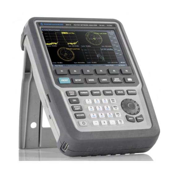
R&S 2 Welcome to the R&S ZNH The R&S ZNH is a new generation Rohde & Schwarz vector network analyzer devel- oped to meet demanding customer requirements. Offering touchscreen input, the ana- lyzer enhances user experience in making measurements fast and easy. -
Page 22: Getting Started
Tour....................... 23 3.1 Preparing for Use 3.1.1 Putting into Operation This chapter describes the basic steps to be taken when setting up the R&S ZNH for the first time. Risk of injury due to disregarding safety information Observe the information on appropriate operating conditions provided in the data sheet to prevent personal injury or damage to the instrument. - Page 23 ® Getting Started R&S Preparing for Use Risk of instrument damage during operation An unsuitable operating site or test setup can cause damage to the instrument and to connected devices. Ensure the following operating conditions before you switch on the instrument: ●...
- Page 24 3.1.1.3 Setting up the R&S ZNH The R&S ZNH is mainly used for diagnostic purpose during the installation of RF feeder cables and antennas for all kinds of radio transmitters. It can also be used to characterize both amplitude and phase measurements on complex test devices and discrete components with its S-parameters measurements.
- Page 25 ● Attach the appropriate adapter to the power supply. Connect the AC adapter to the DC port on the left side of the R&S ZNH (item 1 of Figure 3-1). Make sure to fully insert the AC adapter plug into the DC port.
- Page 26 2 = Power cable The voltage range of the AC power supply is 100 V to 240 V AC. After the R&S ZNH is connected to the power supply, you can turn it on with the [Power] key on the front panel.
- Page 27 HA-Z302, order number 1321.1340.02). You can connect the car adapter to the DC port. With the car adapter, you are able to charge the R&S ZNH via the car's cigarette lighter socket. A replacement battery (R&S HA-Z306, order number 1321.1334.02) with the same capacity and charging time as the battery included in the standard delivery is also available if necessary.
- Page 28 Preparing for Use 3.1.1.6 Battery Maintenance The R&S ZNH comes with a lithium-ion battery. In general, these batteries are easy to handle. When you handle the battery, follow the instruction mentioned in the safety instructions and in the following chapters.
-
Page 29: Switching The Instrument On And Off
18. ► Press [Power] key to switch on the instrument. During booting, the R&S ZNH displays a splash screen to indicate the operable fre- quency range of the instrument. Depending on the frequency upgrade option instal- led, the respective splash screen is loaded. -
Page 30: Instrument Tour
Getting Started R&S Instrument Tour 3.2 Instrument Tour This chapter describes the instrument in different views. 3.2.1 Front View Figure 3-4: Front view of R&S ZNH RF port 1 BNC connector Headphone jack USB ports RF port 2 Touch-sensitive screen area... -
Page 31: Top View
0 dBm, maximum 50 Vdc. Depending on the models, connect a cable or DUT to the RF input with a respective connector. Use a cable to connect the DUT to the R&S ZNH, if necessary. ● With a single RF port, it is possible to generate a stimulus signal and measure the response signal in reflection. - Page 32 The level of the reference signal must be larger than 0 dBm. If there is no reference signal present at the BNC connector, the R&S ZNH displays an appropriate message. Thus, measurements without a valid reference can be avoided.
-
Page 33: Left View
® Getting Started R&S Instrument Tour Risk of instrument damage To avoid damage to the tracking generator output, never apply currents greater than 600 mA or voltages greater than 20 V to the BNC connectors if the BNC connectors are not configured as BIAS output ports. If they are configured as BIAS ports, never apply currents greater than 600 mA or vol- tages greater than 50 V. -
Page 34: Right View
The R&S ZNH is supplied with power by the AC/DC transformer power supply via the DC connector. You can also use the DC connector to charge the battery. Kensington lock slot A Kensington lock can be anchored to the R&S ZNH housing to secure it to a worksta- tion mechanically. 3.2.4 Right View... -
Page 35: Rear View
Instrument Tour 3.2.5 Rear View The micro-SD card slot is located behind the battery compartment of the R&S ZNH. Peel open the micro-SD card protective cap to access to the micro-SD card slot. You can use the micro-SD card to store datasets or screenshots. - Page 36 ® Getting Started R&S Instrument Tour 1 = Title bar 2 = Measurement result view 3 = Measurement trace window 4 = Parameter view 5 = Softkey functions Risk of touchscreen damage during operation ● Never touch the screen with ball point pens or other pointed objects with sharp edges.
-
Page 37: Basic Operation
The following chapters provide an overview on the measurements that you can per- form with the R&S ZNH. ● Screen Layout and Elements.................. 30 ● Configuring the R&S ZNH..................38 ● Connecting the R&S ZNH to a PC................51 ● Managing Options....................58 ● Measuring Transmissions..................61 ●... -
Page 38: Title Bar
® Basic Operation R&S Screen Layout and Elements 11 = Internal DC bias connecting status 12 = Reference position of trace measurement 13 = Selected trace label 14 = Invalid trace indicator 15 = Blue dot implies setting not coupled to another hardware setting 16 = Upper limit line threshold 17 = Trace measurement (up to four can be displayed) 18 = Display line... -
Page 39: Measurement Result View
Chapter 8.4.2, "Using Markers", on page 165. 4.1.4 Measurement Trace Window The measurement trace window is the main user interface window in the R&S ZNH. It displays the trace label, internal DC bias status and measurement traces where mark- ers and limit lines are positioned for measurement. - Page 40 ® Basic Operation R&S Screen Layout and Elements In VNA mode, the R&S ZNH provides up to four measurement traces in the displayed measurement trace windows. Each measurement trace is supported with the following: ● Reference position (index 12 of...
- Page 41 ® Basic Operation R&S Screen Layout and Elements Table 4-2: Measurement trace window combination Types of measurement trace window display "Single" - single display "Dual-Hor" - dual horizontal display "Dual-Vert" - dual vertical display "Triple" - triple display "Quad" - quadrant display User Manual 1334.5985.02 ─...
-
Page 42: Parameter View
® Basic Operation R&S Screen Layout and Elements For more information of trace label, see Chapter 8.2, "Performing Vector Network Analysis Measurements", on page 151 and Chapter 8.1.1, "Calibration States", on page 148. For information of the internal DC bias status, see "Configuring the BIAS output port"... -
Page 43: Configuration Overview
® Basic Operation R&S Screen Layout and Elements Parameter Description "Points" Configure the number of measurement points. Chapter 8.3.4.1, "Changing the Number of Measurement Points", on page 162. "Avg" Toggle the trace parameter to select the different trace mode ("OFF", "ON"). Chapter 8.4.1, "Working with Traces", on page 164. - Page 44 ® Basic Operation R&S Screen Layout and Elements The configuration overview window is divided into six categories: Table 4-3: Corresponding dialog box of configuration overview window "Config Overview" block Corresponding dialog box Description Select "MEAS" to load the availa- ble measurement modes Parameters, Wave, Ratios) to configure the desire trace format...
-
Page 45: Configuring The R&S Znh
Traces", on page 164. 4.2 Configuring the R&S ZNH In the "Instrument Setup" dialog box, the R&S ZNH provides various general settings that are independent of the operating mode of the R&S ZNH. 1. Press [SETUP] key. 2. Select "Instrument Setup" softkey. -
Page 46: Configuring The Hardware
The hardware settings provide settings that control internal and connected hardware. Using auto accessory detection If you are using any accessories while working with the R&S ZNH, the instrument is able to identify the connected hardware. To enable this setting: 1. -
Page 47: Using The Gps Receiver
4. Enter the desired DC bias voltage. 4.2.2 Using the GPS Receiver The R&S ZNH can locate your exact position if you connect the GPS receiver (R&S HA-Z340, order number 1321.1392.02) to the USB connector. User Manual 1334.5985.02 ─ 02... - Page 48 A drop-down menu opens to turn the GPS receiver on or off. 2. Turn the GPS receiver on or off as required. When "GPS" item is turned on, the R&S ZNH is ready to receive GPS data. Displaying GPS information 1.
-
Page 49: Configuring Date And Time
2. Select the coordinate format from the drop-down menu. 4.2.3 Configuring Date and Time The R&S ZNH has an internal clock that can apply a date and timestamp. In the "Instrument Setup" dialog box, you can set both date and time. -
Page 50: Selecting Regional Settings
2. Enter the time you want with the numeric keys. 3. Confirm the entry with the rotary knob. After you have entered the time, the R&S ZNH verifies the validity of the time. If it is not a valid time, it sets to the next valid time. - Page 51 3. Reboot the device to activate the choice of selected language. Setting the date format The R&S ZNH provides two different formats to display the date. 1. In the "Instrument Setup" dialog box, select the "Date Format" item. A drop- down menu opens to select the date format.
-
Page 52: Configuring The Display
2. Select the required date format from the drop-down menu. Setting the length unit The R&S ZNH provides two different formats to configure the cable length unit. 1. In the "Instrument Setup" dialog box, select the "Length Unit" item. A drop- down menu opens to select the length unit. - Page 53 ® Basic Operation R&S Configuring the R&S ZNH The backlight intensity is a percentage from 0% to 100% with 100% being the brightest. 3. Confirm the entry with the rotary knob. Adjusting the display color scheme 1. In the "Instrument Setup" dialog box, select the "Display Color Scheme" item.
-
Page 54: Configuring The Audio Output
The audio settings control the audio output of the system. Setting the key click volume The key click volume sets the volume of the sound that the R&S ZNH produces when you press a key or select a softkey. 1. In the "Instrument Setup" dialog box, select the "Key Click Volume" item. -
Page 55: Configuring Power Supply
3. Confirm the entry with the rotary knob. Activating / Deactivating audio alert for power overload In case the R&S ZNH detects an overload at one of its inputs, you can configure the alert audible 1. In the "Instrument Setup" dialog box, select the "Beep on Power Overload" item. -
Page 56: Configuring Calibration Kit Model
3. Confirm the entry with the rotary knob. Activating / Deactivating audio alert for battery low-level state The R&S ZNH also allows you to turn on an audio signal that indicates that the battery has reached its low-level state. 1. In the "Instrument Setup" dialog box, select the "Battery Low Level Beep" item. -
Page 57: Resetting The R&S Znh
The R&S ZNH opens a file manager dialog to select the calibration kit model. 2. Select the calibration kit model that you require. The R&S ZNH loads the selected calibration kit model which is taken in for consid- eration during the calibration. -
Page 58: Connecting The R&S Znh To A Pc
Resetting the R&S ZNH A "Reset to Factory Settings" resets the R&S ZNH to the factory defaults. During a reset, the R&S ZNH restores the original configuration. It also deletes all cus- tomized datasets (limit lines, standards, channel tables, transducer tables etc.). -
Page 59: Lan Connection
For a direct connection between the PC and R&S ZNH, the DHCP (Dynamic Host Con- figuration Protocol) of the R&S ZNH has to be turned off (which is the default state). 1. In the "Instrument Settings" dialog box, select the "DHCP" item. - Page 60 ® Basic Operation R&S Connecting the R&S ZNH to a PC 2. In the "Instrument Settings" dialog box, select the "Subnet Mask" item. 3. Enter the subnet mask of the PC with the numeric keys. After you have matched the subnet mask, you can define the IP address. When both devices are in the same subnet, the first three digits of the IP address are usually the same.
- Page 61 ® Basic Operation R&S Connecting the R&S ZNH to a PC 4. Enter the IP address of the PC with the numeric keys. Configuring the R&S InstrumentView software package 1. Start the R&S InstrumentView software. 2. Select the "LAN" tab in the screen layout.
- Page 62 ® Basic Operation R&S Connecting the R&S ZNH to a PC 5. Specify a name and the IP address for the new network connection. 6. Select "Local Area Connection" for the "Network Adapter". 7. Confirm the entry with the "OK" button to add the new instrument to the connection manager list.
- Page 63 Connecting the R&S ZNH to a PC Connecting the R&S ZNH in an existing LAN You can either get the R&S ZNH IP address automatically from the DHCP server or manually assign a fixed address. With manual allocation, a fixed IP address and subnet mask must be assigned to the R&S ZNH as described in...
-
Page 64: Usb Connection
1. In the "Instrument Setup" dialog box, select the "DHCP" item. 2. Select "DHCP" to "On" to activate the DHCP. The R&S ZNH is now allocated an IP address and the subnet mask by the DHCP server. This can take several seconds. -
Page 65: Managing Options
Managing Options Figure 4-3: USB connection 4.4 Managing Options For special measurement tasks, you can equip the R&S ZNH with various firmware options. 4.4.1 Enabling Options To enable options, you have to enter a key code. The key code is based on the unique serial number of the R&S ZNH. -
Page 66: Checking Options
In the "Setup" menu, the R&S ZNH shows all options that are currently installed. 1. Press [SETUP] key. 2. Select "Installed Options" softkey. The R&S ZNH shows a list of all available options and the current status of the option: ●... -
Page 67: Managing Options With R&S License Manager
Managing Options 4.4.3 Managing Options with R&S License Manager If you are using the R&S ZNH in a local area network (LAN), you can manage the firm- ware options with a web browser (e.g. Microsoft Internet Explorer or Mozilla Firefox). -
Page 68: Measuring Transmissions
Connect the output of the filter to the RF input (RF port 2). Preset the R&S ZNH Before starting the measurement procedure, preset the R&S ZNH to restore the default configurations and connect the filter between the measurement ports. User Manual 1334.5985.02 ─ 02... - Page 69 The R&S ZNH adjusts the frequency range accordingly. Note that the distance from start to stop frequency has to be equal to the span. The R&S ZNH adjusts the values if you enter a frequency range that is not the same as the span.
-
Page 70: Transmission Measurement
10. Proceed with "Through" to start the normalization calibration from "Port1" to "Port2". After finishing the calibration routine, the R&S ZNH highlights the "Through" in blue. The R&S ZNH is now calibrated and a "(norm)" status is displayed next to the mea- surement format, i.e. . See Chapter 3.2.6, "Display Overview",... -
Page 71: Reflection Measurement
Note on the following differences: ● The basic test setup for reflection measurements involves a single DUT and ana- lyzer port. You connect the input of your DUT to port 1 of the R&S ZNH. ● Using the basic... -
Page 72: Using A Power Sensor
For a list of R&S ZNH supported power sensors, see the datasheet of the R&S ZNH. You can connect the list of supported power sensors to the USB port of the R&S ZNH. This connector allows you to control the power sensor and supplies it with power. For more information, see "USB type A connector"... - Page 73 However, brief power peaks ≤ 10 μs up to 1 W (30 dBm) are permissible. Test setup Connect the power sensor cable to the USB port of R&S ZNH. If the power sensor is having the binder connector (i.e R&S FSH-Z1, R&S FSH-Z18), the FSH-Z101 adaptor cable is needed.
- Page 74 After zeroing, the R&S ZNH displays the message "Power sensor zero done" and again shows the power sensor softkey menu. 5. Connect the DUT to the power sensor. The R&S ZNH shows the measured power level in dBm. For more information, see Chapter 10.1, "Using a Power Sensor", on page 171.
-
Page 75: Measuring Power And Return Loss
Screw the RF connectors tightly. Test setup Connect the power sensor cable to the USB port of R&S ZNH. If the power sensor is having the binder connector (i.e R&S FSH-Z14, R&S FSH-Z44), the FSH-Z144 adaptor cable is needed. Insert the directional power sensor between the source and the load. -
Page 76: Saving And Recalling Results And Settings
Measuring the power 1. Press [MODE] key. 2. Select "Power Meter" softkey. As soon as the R&S ZNH recognizes the power sensor, it displays the type of the directional power sensor that is connected in the title bar. After a few seconds, it also shows the forward power and return loss currently measured at the load. - Page 77 ® Basic Operation R&S Saving and Recalling Results and Settings For more information on saving measurement results and settings, see Chapter 5.8.1, "Saving Datasets", on page 88. For more information on recalling measurement results and settings, see Chap- ter 5.8.2, "Restoring Datasets", on page 90.
-
Page 78: Instrument Functions
Documentation.................... 93 5.1 Touchscreen Gesture Element To enhance greater flexibility and user experience in the user interaction with R&S ZNH, special touchscreen gestures are introduced. The following illustrated the list of special gestures that R&S ZNH provides. ● Change Center Frequency..................71... -
Page 79: Change Reference Level
® Instrument Functions R&S Touchscreen Gesture Element 5.1.2 Change Reference Level Swipe up or down vertically in the trace window to adjust the reference level of the spectrum measurement. Alternatively, select the "REF" softkey in the Parameter View to adjust the reference level or press the [SCALE] / [SCALE/AMPT] key on the front panel to display the "Ref Level"... -
Page 80: Add Marker
® Instrument Functions R&S Touchscreen Gesture Element 5.1.4 Add Marker Double tap in the trace window to create a marker on the spectrum measurement. The marker is placed on the trace where the double tab gesture is performed. Alternatively, press the [MARKER] key on the front panel and select the "New Marker" softkey to create a marker on the spectrum measurement. -
Page 81: Delete All Markers
® Instrument Functions R&S Touchscreen Gesture Element 5.1.6 Delete All Markers Draw an "X" on the trace window to delete all markers from the spectrum measure- ment. Alternatively, press the [MARKER] key on the front panel and select the "Delete Marker"... -
Page 82: Preview Screenshot
® Instrument Functions R&S Touchscreen Gesture Element 5.1.8 Preview Screenshot Swipe horizontally to the left or right direction in the trace window to preview the screenshot. Alternatively, select the "Prev" or "Next" softkey to preview the screenshot. 5.1.9 Skip Wizard Measurement Swipe horizontally to the left direction to skip a wizard measurement. -
Page 83: On-Screen Keyboard
® Instrument Functions R&S On-screen Keyboard 5.2 On-screen Keyboard The on-screen keyboard is an additional means of interacting with the instrument. It provides convenience of usage with the touchscreen input. Accessing the on-screen keyboard is only available for text-based entry, e.g. save or open a filename. -
Page 84: Front Panel Keys
® Instrument Functions R&S Front Panel Keys 5.3 Front Panel Keys The following chapters illustrate the function of the front panel keys. 5.3.1 POWER Key The [POWER] key is located on the lower left of the front panel. It starts up and shuts down the instrument. -
Page 85: Function Keys
[CAL] The [CAL] key provides the following functions: ● Performs calibration on the R&S ZNH. ● Selection of calibration kit models, calibration ports and cal- ibration methods for measurement. ●... - Page 86 ® Instrument Functions R&S Front Panel Keys FUNCTION keys Descriptions [SCALE/AMPT] Mode-dependent button. The [SCALE/AMPT] key provides the following functions: ● Sets the reference level, dynamic range of the reference level and auto scaling of the reference level. ● Sets tracking generator power and receiver attenuation. For more information, see Chapter 8.3.2, "Configuring the Verti- Axis",...
-
Page 87: Keypad
This key provides functionality to select and configure measure- ments in the available measurement modes. For more information, see the corresponding measurement modes in the R&S ZNH user manual. [MARKER] Mode-dependent button. Sets and positions the absolute and relative measurement mark- ers (markers and delta markers). -
Page 88: Navigation Controls
® Instrument Functions R&S Front Panel Keys Type of key Description Unit keys (GHz/- These keys add the selected unit to the entered numeric value and complete the dBm MHz/ dBm, entry. kHz/dB and Hz/dB) In the case of level entries (e.g. in dB) or dimensionless values, all units have the value "1"... -
Page 89: Presetting The R&S Znh
Before you prepare a measurement, it is recommended to preset the R&S ZNH. During a preset, the R&S ZNH resets all settings to their default state. Restoring the default configuration has the advantage that old settings do not affect measurements. -
Page 90: Configuring Measurements
5.5 Configuring Measurements Configuration Overview dialog box provides an overview of the current configura- tion of the R&S ZNH. In addition, you can also change the configuration in this dialog box. 1. Press [SETUP] key. 2. Select "Config Overview" softkey. -
Page 91: Taking Screenshots
The R&S ZNH takes the screenshot. If available, the R&S ZNH stores the screenshot on an external storage device (USB flash drive or micro-SD card). If both are connected, the R&S ZNH uses the USB flash drive. If no external device is available, the R&S ZNH stores the screenshot in its internal memory until the internal memory is full. - Page 92 75. 1. Press [SAVE/RECALL] key. 2. Select "File Manager" softkey. The R&S ZNH opens the file manager to select a screenshot for the preview. 3. Select the screenshot for preview. 4. Select "Preview" softkey to preview the screenshot.
-
Page 93: Managing Datasets
Datasets The R&S ZNH supports various types of datasets. The instructions below primarily describe the management of datasets that you create on the R&S ZNH during mea- surements, for example measurement results and configurations. Note that these data- sets have the file extension .set. - Page 94 R&S InstrumentView software package. Data synchronization The R&S InstrumentView features data synchronization that matches the data availa- ble between the R&S ZNH and the PC. 1. Select "File Transfer" from the "Instrument" menu. The software opens the "File Transfer" dialog box.
-
Page 95: Saving Datasets
● Deleting Datasets....................92 5.8.1 Saving Datasets The R&S ZNH allows you to save the data that is analyzed at any time. 1. Press [SAVE/RECALL] key. 2. Select "Save" softkey. The R&S ZNH opens the "Save Dataset" dialog box. Figure 5-2: Save Dataset dialog box... - Page 96 88. The internal memory provides approximately 20 MB of data, therefore the number of datasets you save on the R&S ZNH is limited. Each dataset needs about 100 kB of memory, but this value can vary. If you are using an external storage device, the number of datasets you can save is limited only by the size of the storage device.
-
Page 97: Restoring Datasets
The R&S ZNH displays a submenu for selection. 5. Select "Rename" menu item to rename the files or file directories. The R&S ZNH opens an input field to change the name of the selected files or file directories. 5.8.2 Restoring Datasets You can preview and load previous saved measurement results with the recall function of the R&S ZNH. - Page 98 The R&S ZNH provides the function to preview datasets. The preview function allows you to take a quick look at the screenshot and its corresponding measurement set- tings. During preview, the R&S ZNH does not yet activate the measurement settings of that dataset.
-
Page 99: Deleting Datasets
If you find a dataset whose settings you need for your current measurement task, you can load it. ► Select "Load" softkey. The R&S ZNH loads the dataset and adjusts its measurement settings according to the dataset. See also Chapter 5.8.2.1, "Previewing a Dataset",... -
Page 100: Updating The Firmware
R&S Device Documentation Before deleting, the R&S ZNH shows a warning message that you need to confirm. 6. Select "Yes" to delete the selected files or file directories. The R&S ZNH deletes the selected files or file directories from its memory. - Page 101 ® Instrument Functions R&S Device Documentation 5. Select "Export" to export documentation from the instrument. The R&S ZNH export the documentation into the selected file location. User Manual 1334.5985.02 ─ 02...
-
Page 102: Working With The Measurement Wizard
Before you can use the measurement wizard, you have to define a measurement set using the "Wizard Set Editor" in the R&S InstrumentView software package. The R&S InstrumentView software package is delivered with the R&S ZNH. The latest version is also available for download on the R&S ZNH website at http://www.rohde-... - Page 103 Working with the Measurement Wizard R&S Performing and Configuring Measurements Load the measurement wizard Now that the measurement set is available on the R&S ZNH, you can perform the measurement wizard. 1. Press [Wizard] key. The R&S ZNH opens the wizard dialog box. See Figure 6-1.
- Page 104 If you reduce the number of measurements, the R&S ZNH omits the last measurement in the sequence. You can edit this field only if you turned on the "Allow Vari- able Number of Sequence Steps" in the "Wizard Set Editor"...
- Page 105 Select "On" to use the predefined cable characteristics or "Off" to redefine the cable model and cable length in R&S ZNH. In the case, if "On" is selected, the parameters below will be locked. Cable Model Cable model that you perform the measurement on. You can define a cable model with the R&S ZNH software, but...
- Page 106 Performing a sequence of measurements Calibration data The R&S ZNH adds the calibration data of each calibration you perform to a calibration data folder available on its internal memory. Each dataset in the calibration data folder is unique for a particular calibration method and a particular measurement configura- tion.
- Page 107 3 = See Table 6-2 1. Select "Start Meas" softkey. If you have not yet calibrated the R&S ZNH for the measurement, it asks you to perform the calibration routine. The stages of the calibration depend on the defined calibration routine. See Chapter 7.1.7, "Calibrating...
- Page 108 – Select "Cancel" softkey if at any time the result does not match your expectation and you want to abort the measurement. The R&S ZNH prompts you to save measurement result and exit the wizard measurement. ● Select "Interrupt" softkey.
- Page 109 This feature is available when you activated the "Prompt User to Change Cable Settings" in the "Wizard Set Editor" of the R&S InstrumentView software. When this function is activated, the R&S ZNH asks you to select new cable charac- teristics during the preparation of a measurement.
- Page 110 Working with the Measurement Wizard R&S Performing and Configuring Measurements Select "Continue" softkey. The R&S ZNH prompts you to save or discard the mea- surement results. Select "Save Result" softkey to save the results on the selected storage device or "Discard Result"...
-
Page 111: Evaluating Results
The syntax is 'site- name_measurement_#'. The R&S ZNH adds numbers in ascending order to the files and directories if you per- form a measurement or measurement set more than once. 6.2 Evaluating Results The R&S InstrumentView software package provides functionality to evaluate results... - Page 112 ® Working with the Measurement Wizard R&S Evaluating Results 3. Select the reporting parameters checkmarks that you want to show in the report, e.g. checkmark to show marker data. 4. Select "Generate" button to create the report. For more information on the report generator function, see the R&S InstrumentView user manual.
-
Page 113: Cable And Antenna Test Mode
Figure 7-1: Typical defects in a transmission system The R&S ZNH provides the necessary functionality to test the system equipment for its characteristics and identify faults when it is being installed or maintained. ●... - Page 114 For more information, see "Configuring the BIAS output port" on page 40. By default, the R&S ZNH is in the VNA mode after you have turned it on. To switch to the CAT mode, proceed as follows. 1. Press [MODE] key.
-
Page 115: Performing Cable And Antenna Measurements
7.1 Performing Cable and Antenna Measurements In order to get an idea about the problems in a transmission system that is as accurate as possible, the R&S ZNH features several measurements. Each measurement shows a different aspect of the cable characteristics. -
Page 116: Reflection Measurements
The R&S ZNH starts the S22 reflection measurement. 5. To change the measurement format, press [FORMAT] key. The R&S ZNH displays the available measurement formats for "Return Loss" mea- surement. 6. Select "db Mag", "SWR", "Phase" or "Smith" softkey. - Page 117 1. Press [MEAS] key. 2. Select "Return Loss" or "Transmission" softkey. The R&S ZNH starts the default measurement format over its entire frequency range. 3. Select "RL + Trans" menu item. The R&S ZNH displays the combine measurements over its entire frequency range.
- Page 118 7.1.1.1 Managing S-Parameters File The R&S ZNH is able to export the reflection measurements trace as S1P and S2P file in Touchstone format 1.1. To export the file, do the following: 1.
-
Page 119: Distance To Fault Measurements
The distance to fault (DTF) measurement determines the exact location of possible faults in a transmission system. If you connect the end of the cable to the R&S ZNH, the DTF measurement shows you the exact distance to the fault (in meter or feet), regardless by what the fault is caused. - Page 120 Because of its sensitivity by first measuring in the frequency domain and subsequent IFFT, the measurement is able to locate faults in a cable accurately. To keep this accu- racy, the R&S ZNH also accounts for any attenuation that occurs over distance in a cable.
- Page 121 The R&S ZNH displays the DTF configuration submenu. 3. Select "Split Screen" softkey. The R&S ZNH displays the DTF measurement in the top screen window and the reflection measurement in the bottom screen window. 4. Tap on the desired trace window to select the screen window.
-
Page 122: 1-Port Cable Loss Measurement
By default, the R&S ZNH evaluates the cable loss over its entire frequency range (full span of the R&S ZNH). When you reduce the span, make sure to define a span that is appropriate for the measurement, especially for high center frequencies, and consider the cable length and the wavelength of the selected center frequency. -
Page 123: Transmission Measurements
1. Press [MEAS] key. 2. Select "Transmission" softkey. By default, the R&S ZNH starts the forward transmission measurement, S21 with default measurement format over its entire frequency range. 3. To perform S12 measurement, select "Port 2" menu item from "Driving Port" soft- key. -
Page 124: Smith Chart
The R&S ZNH starts the reflection measurement with default measurement format over its entire frequency range. 3. Press [FORMAT] key. 4. Select "Smith" menu item. The R&S ZNH shows the reflection of the DUT in smith chart. User Manual 1334.5985.02 ─ 02... - Page 125 Shows the group delay at the current marker position. ► Press [MARKER] key. The R&S ZNH activates a marker and opens the marker softkey menu. Like usual traces, you can move the marker around with the rotary knob or enter a specific marker position.
-
Page 126: Phase Measurement
Cartesian diagram with a linear vertical axis. The horizontal axis repre- sents the measured frequency range. In the default state, the R&S ZNH shows the phase only from -200° to +200°. In that case, the R&S ZNH displays measurement results correctly only if the phase difference between two adjacent test points is less than 180°. -
Page 127: Calibrating Measurements
"Delay Time" - Enable or disable the check box to display cable delay time. 7.1.7 Calibrating Measurements In its default state, the R&S ZNH uses factory calibration. Factory calibration is a full 2- port calibration over the full frequency range (i.e. span) of the R&S ZNH. When the fac- tory calibration is active, no calibration status is shown on the trace label. - Page 128 Calibration also remains valid after turning off the R&S ZNH or changing into another operating mode as calibration data is saved in the internal memory of the R&S ZNH. If you save the measurement in a dataset, calibration data is part of that dataset. When you restore the dataset and perform the same measurement again, you do not have to recalibrate the R&S ZNH.
- Page 129 "Trans Norm P1", "Trans Norm P2" and "Trans Norm Both". User calibration After a user calibration is performed, the R&S ZNH allows you the option to apply user calibration ("cal" or "norm") or resume factory calibration data on the measurement.
-
Page 130: Configuring Cable And Antenna Tests
If you want to test a cable that is not listed, you can also define cable models manually, either directly on the R&S ZNH or with the "Cable Model Editor" of the R&S InstrumentView software package that is delivered with the R&S ZNH. - Page 131 The R&S ZNH opens the file manager to select a cable model. 5. Select the cable model that you are testing. The R&S ZNH loads the selected cable model. Note that the selected cable model is also displayed in the title bar.
- Page 132 The first way is to define a cable model with the "Cable Model Editor" that is part of the R&S InstrumentViewsoftware package. The R&S InstrumentView is delivered with the R&S ZNH. With this software, you can define a cable model on a computer and then transfer it to the instrument.
-
Page 133: Configuring The Horizontal Axis
2. Select "DTF Config" softkey. The R&S ZNH displays the DTF configuration submenu. 3. Select the "DTF List" softkey. The R&S ZNH opens a table that lists the peaks it has found during the measure- ment. 1 = Shows the peak results 2 = Shows the distance from the measurement plane to the peak. - Page 134 Setting the Frequency Range for DTF Measurements In the default settings, the R&S ZNH automatically selects a center frequency of 1 GHz and a distance of 50 m. The R&S ZNH optimizes the settings for the best resolution, if you change the stop distance.
- Page 135 The R&S ZNH adjusts the frequency range according to your settings. Note that the distance from start to stop frequency has to be equal to the span. The R&S ZNH adjusts the values if you enter a frequency range that is not the same as the span.
- Page 136 In auto span mode, the R&S ZNH adjusts the frequency settings in order to get the best display resolution. If you have set the span manually, the R&S ZNH zooms in to the section of the cable you have defined. The results maintain their accuracy in that case.
-
Page 137: Configuring The Vertical Axis
When you change the reference value, the R&S ZNH adjusts the labels of the vertical axis. Changing the reference value results a change in the vertical position of the trace. - Page 138 The "0" value corresponds to the top grid line and the "10" corresponds to the bottom grid line. When you change the reference position, the R&S ZNH also shifts the position of the trace by the magnitude of the reference position change. It has no effect on the refer- ence value itself.
-
Page 139: Configuring The Tracking Generator
The R&S ZNH opens an input field to specify the measurement bandwidth. 3. Enter the measurement bandwidth you require. As an indicator that the "Meas BW" is no longer coupled to the span, the R&S ZNH displays a blue dot in front of the "Meas BW" item in the parameter view. -
Page 140: Setting The Measurement Sweep
Single sweep mode performs the sweep in the defined span once, then the R&S ZNH goes into an idle state. If the trace averaging is set, the R&S ZNH performs the sweep a certain number of times (depending on the number of averages you have set) over the defined span and then stops measuring. -
Page 141: Analyzing Measurement Results
R&S Analyzing Measurement Results 7.2.6.3 Measurements Hold The R&S ZNH provides a hold function that stops the display update and leaves room for further analysis of the measurement results. 1. Press the [SWEEP] key. 2. Select the "Hold" softkey. The R&S ZNH interrupt the display update. - Page 142 7.3.1.3 Working with Memory Traces The R&S ZNH can transfer a trace to the trace memory and also display the current trace and the trace in the trace memory for comparison. The saved trace is always dis- played in a lighter yellow to distinguish it from the current trace. See Figure 7-9.
-
Page 143: Using Markers
7.3.2.1 Using Markers and Deltamarkers The R&S ZNH has six markers, five of which can be used as either markers or delta markers. The markers cannot leave the trace and indicate the horizontal and vertical coordinates of the point they are positioned on. - Page 144 ® Cable and Antenna Test Mode R&S Analyzing Measurement Results the delta marker level unit is always dB. The delta marker frequency is always relative to the main marker – in other words, the delta marker frequency is the frequency differ- ence between the frequency at the point marked by the main marker and the frequency at the point marked by the delta marker.
- Page 145 The R&S ZNH activates a delta marker and positions it on the next maximum level that has been measured. In addition, the delta marker input field opens. The R&S ZNH adds the delta marker to the marker list and shows the marker posi- tion relative to the normal marker (M1).
- Page 146 M2) and its coordinates are now absolute values. Automatic Positioning of Markers The R&S ZNH offers functions that make setting the markers easier or allow to make instrument settings on the basis of the current marker position: 1. Press the [MARKER] key.
- Page 147 3. Select the "Delete All" menu item. The R&S ZNH deletes all markers and delta markers. Using Marker Search Limits The R&S ZNH allows you to use only a limited section of the trace for the marker auto- matic positioning functions. See "Automatic Positioning of Markers"...
- Page 148 7. Confirm the entry with one of the unit keys. If the span is wide enough, the R&S ZNH displays a blue and green line to indicate the limit line for "Search Range 1" and "Search Range 2" respectively. By default, the search limit range is over the whole span.
-
Page 149: Using Display Line
1. Press the [LINES] key. 2. Select the "Display Line" softkey. The R&S ZNH displays the display line as a blue horizontal line. It shows the verti- cal position of the line in a table above the diagram area. When you activate the display line, the R&S ZNH also opens an input field to define the vertical position of the line. - Page 150 Values that define the vertical characteristics are always level values in dB. If the scal- ing of the vertical axis is currently a linear one (units V or W), the R&S ZNH automati- cally switches to a logarithmic scaling after you turn on the limit line.
- Page 151 Before selecting a limit line, you need to decide if you want to use it as an upper or lower limit line. In case of upper limit lines, the R&S ZNH checks if the signal is above the limit line. In case of lower limit lines, the R&S ZNH checks if the signal is below the limit line.
- Page 152 As long as the signal does not violate the limit line, the R&S ZNH shows a "Pass" message in the measurement diagram. When one single value (i.e. one pixel) is outside of the limits, the R&S ZNH displays a "Fail" message in the diagram area and, in addition, sounds a beep.
-
Page 153: Vector Network Analysis
The network analyzer mode provides the functionality to characterize networks with one or two test ports. All R&S ZNH models have a tracking generator and VSWR bridge that are necessary to use the network analyzer. The network analyzer provides measurements to deter- mine the reflection or transmission characteristics in both directions of the device under test (DUT). -
Page 154: Calibrating Measurements
6. Confirm the value with a unit key. 8.1 Calibrating Measurements In its default state, the R&S ZNH uses factory calibration. Factory calibration is a full 2- port calibration over the complete frequency range of the R&S ZNH model. By default, the factory calibration is active, but this can be overwritten by user calibration (see Chapter 8.1.3, "Performing... -
Page 155: Calibration States
Calibration remains valid after turning off the R&S ZNH or changing into another oper- ating mode as calibration data is saved in the internal memory of the R&S ZNH. If you save the measurement in a dataset, calibration data is part of that dataset. When you restore the dataset and perform the same measurement again, you do not have to recalibrate the R&S ZNH. -
Page 156: Calibration Methods
® Vector Network Analysis R&S Calibrating Measurements 8.1.2 Calibration Methods The R&S ZNH provides several calibration methods on one or two test ports for vector measurements. ● Refl Norm Open The reflection normalization calibration routine requires connection of the Open standard to the selected test ports. -
Page 157: Performing Calibration
4. Select the "Ports" ("Port1" and/or "Port2") to define the port assignments between the R&S ZNH and the calibration unit. The R&S ZNH extracts the "Connector" type and "Gender" of the connector from "Calibration Kit" file. 5. Select the calibration "Type" to perform the calibration standard. -
Page 158: Performing Vector Network Analysis Measurements
If you want to change the calibration configuration, select the "Cal Config" to make changes. 9. Select "Start Cal" to proceed the user calibration. The R&S ZNH displays the calibration dialog with respect to the saved calibration configuration. The following illustrates an example of the calibration standards associated to the USOM calibration method saved in the calibration configuration. -
Page 159: S-Parameter Measurements
Simultaneously display of up to four different trace measurements (S-Parameters, Wave, Ratios) and formats (dB Mag, Linear, Phase, Smith, SWR, Polar and Group Delay) are possible via the [TRACE] > "Display" softkey selection. The R&S ZNH can displays a combination of up to four measurement trace windows,... - Page 160 ® Vector Network Analysis R&S Performing Vector Network Analysis Measurements Figure 8-4: 2-port measurement with signal flows = Incident wave at port 1 = Outgoing wave at port 1 = Outgoing wave at port 2 = incident wave at port 2 = Reflection coefficient of DUT, the ratio between b and a in a forward measurement with matched...
-
Page 161: Wave Measurements
Chapter 4.5.2, "Reflection Measurement", on page 64. 8.2.2 Wave Measurements R&S ZNH option R&S ZNH-K66 (order number 1334.6869.02) option is required for the wave measure- ments. See also Chapter 8.2.2, "Wave Measurements", on page 154. A wave quantity measurement provides the power (dBm) of any of the transmitted or received waves. -
Page 162: Ratios Measurements
Vector Network Analysis R&S Performing Vector Network Analysis Measurements 3. Select "Driving Port" to switch signal source on the driving port. The R&S ZNH display a submenu to select "Port 1" or "Port 2" for the signal source. With reference to Figure... - Page 163 The R&S ZNH displays a submenu to select the ratio element. 5. Select "Driving Port" to switch signal source on the driving port. The R&S ZNH displays a submenu to select "Port 1" or "Port 2" for the signal source.
-
Page 164: Configuring Vector Network Analysis
Changing the Reference Value Changing the reference value works like an attenuation or gain in that it moves the trace to another level. The R&S ZNH adjusts the scale of the vertical axis accordingly. For more information, see Chapter 7.2.3.1, "Setting the Reference Value",... - Page 165 131. 8.3.2.3 Defining the Display Range Changing the display range of the R&S ZNH modifies the value of the vertical axis of the measurement diagram of the selected trace. For more information, see Chapter 7.2.3.2, "Defining the Display Range",...
-
Page 166: Selecting The Measurement Format
The R&S ZNH highlights the trace label. 2. Press the [SCALE/AMPT] key. 3. Select the "Couple Traces" softkey. The R&S ZNH aligns the vertical settings of all display traces to the selected trace settings. 8.3.3 Selecting the Measurement Format Different trace formats allow you to express and display the results, depending on what you want to learn from the data. - Page 167 The horizontal axis repre- sents the measured fre- quency range. In the default state, the R&S ZNH shows the phase only from -200° to +200°. In that case, the R&S ZNH displays mea- surement results cor-...
-
Page 168: Setting The Sweep Parameters
DUT. The default formats are activated automatically when the measured quantity changed. 1. Press the [FORMAT] key. The R&S ZNH displays available formats of the measured quantity. 2. Select "More" to display more measured quantity. - Page 169 Hence the measurement time increases roughly linearly with the number of points. 1. Press the "Number of Points" softkey. The R&S ZNH opens an input field to define the measurement points. 2. Key in the required measurement points. 8.3.4.2 Setting the Measurement Bandwidth The measurement bandwidth determines the noise figure of the receiver.
-
Page 170: Analyzing Measurement Results
However, for measurements perform under certain signal conditions, you can use the triggering function. A trigger responds to certain events. If a trigger is active, the R&S ZNH starts to measure if the trigger conditions are met. The trigger can be gener- ated either externally or internally. -
Page 171: Working With Traces
"Delete All": All traces except "Trc1" are deleted from the display measurement trace windows. 3. Delete the required trace. 8.4.1.2 Selecting the Trace Mode The R&S ZNH provides two trace modes to write the trace: "Average On" and "Aver- age Off". For more information, see Chapter 7.3.1.1, "Setting the Trace Mode", on page 134. -
Page 172: Using Markers
1. Press the [MARKER] key. If no marker has been activated, the R&S ZNH automatically activates the main marker and positions it on the maximum level that has been measured. In addition, the marker frequency input field opens. -
Page 173: Using Display Lines
1. Press the [MARKER] key. If no marker has been activated, the R&S ZNH automatically activates the main marker and positions it on the maximum level that has been measured. In addition, the marker frequency input field opens. - Page 174 You can create and edit limit lines with the R&S InstrumentView software and load them into the R&S ZNH via the USB or the LAN interface. The number of limit lines the R&S ZNH can store in its memory depends on the number of other data sets on the R&S ZNH...
-
Page 175: Vector Voltmeter
R&S ZNH-K45 (order number 1334.6852.02) option is required to operate the R&S ZNH in the vector voltmeter mode. Equipped with R&S ZNH-K45, you can use a R&S ZNH with tracking generator and VSWR bridge as a vector voltmeter. A vector voltmeter performs reflection (S11) and transmission measurements (S21). -
Page 176: Calibrating Measurements
Performing Voltmeter Measurements 1. Press the MODE key. 2. Press the "Vector Voltmeter" softkey. The R&S ZNH starts the vector voltmeter mode. It turns on the tracking generator and the zero span mode. 9.1 Calibrating Measurements To get the best and most accurate results, you have to calibrate the measurement. The reflection and transmission measurement of the vector voltmeter each have their own calibration procedures. -
Page 177: Analyzing Measurement Results
3. Set the required power level. 4. Select "Receiver Att" to attenuate the receiving power at the RF input. The R&S ZNH opens an input field to attenuate the receiving power at the RF input of R&S ZNH . 5. Set the required attenuation level. -
Page 178: Power Meter
Sensor................ 176 10.1 Using a Power Sensor The power sensor function turns the R&S ZNH into a wideband power meter. It then always measures the power of the whole signal in the frequency range of the power sensor. In most cases, the signal shape has no effect on the measurement. -
Page 179: Connecting A Power Sensor
10 = Configuration overview icon 11 = Power sensor softkey menu 10.1.1 Connecting a Power Sensor The R&S ZNH controls and powers the power sensors via the USB interface on the top of the instrument. See "USB type A connector"... -
Page 180: Performing And Configuring Measurements
Refer to the documentation of the power sensor for more information on the maximum input power. If the R&S ZNH recognizes a power sensor, it sets up a connection via the interface and after a few seconds shows the measured power. It displays the type of the power sensor in the display header. - Page 181 Do not apply power during the zeroing process, as the power sensor cannot distinguish between external powers and internal offsets. 1. Select "Zero" softkey. 2. The R&S ZNH asks you not to apply any signals to the power sensor during the zeroing process. 3. Disconnect the power sensor from any signal sources.
- Page 182 The R&S ZNH adjusts the result display accordingly. Setting the reference level If you have selected the unit dB Rel, the R&S ZNH opens an input field to set the refer- ence level. The R&S ZNH shows the currently set reference level in the diagram header.
-
Page 183: Using A Directional Power Sensor
The R&S ZNH takes the offset value into account in the power or level display. Activating signal source The R&S ZNH provides the setting to enable or disable the built-in signal source in the power meter mode. Once the signal source is enabled, you can output a signal source of -10 dBm at the designated frequency from the RF output connector. -
Page 184: Connecting A Directional Power Sensor
Connect the power sensor cable via the USB to binder adapter to the USB port of R&S ZNH. The power sensor itself is located between the source and the load of the test setup. -
Page 185: Performing And Configuring Measurements
Risk of skin burns and / or damage to the R&S ZNH Measuring high powers may lead to skin burns and / or damage to the R&S ZNH. You can avoid it by: ●... - Page 186 175. Setting the reference level If you have selected the unit dB Rel for the forward power, the R&S ZNH opens an input field to set the reference level. The R&S ZNH shows the currently set reference level in the diagram header.
- Page 187 The R&S ZNH opens an input field to define the reference offset. 2. Enter the offset you require. The R&S ZNH takes the offset value into account in the power (level) and matching results. If high powers are applied that exceed the maximum input level of the R&S FSH-Z14 or R&S FSH-Z44, a directional coupler or an attenuator has to be connected ahead of...
-
Page 188: Performing Pulse Power Measurements
2. Select "Power Meter" softkey The R&S ZNH activates the mode for power measurements. Connecting the power sensor You can connect the wideband power sensors to the USB port of the R&S ZNH. For more information, see Chapter 10.1.1, "Connecting a Power Sensor",... - Page 189 ® Performing Pulse Power Measurements R&S Figure 11-1: Power vs time display 1 = Connected power sensor model and type of algorithm for power calculation 2 = Numerical results showing the pulse characteristics 3 = Reference for relative power measurements 4 = Video bandwidth 5 = Power offset Configuring the BIAS output port...
- Page 190 ® Performing Pulse Power Measurements R&S Figure 11-2: Graphical representation of pulse characteristic Pulse characteristic Description "Pulse Width" Time that the pulse remains at the top level ("ON"). This is the time between the first positive edge and the subsequent negative edge of the pulse in sec- onds, where the edges occur at crossings of the mid threshold.
-
Page 191: Configuring The Numerical Result Display
Chapter 10.1.2, "Performing and Configuring Measure- ments", on page 173. 11.2 Configuring the Power vs Time Result Display The R&S ZNH allows you to configure several aspects of the power vs time result dis- play and the way the pulse is measured. ● Determining Pulse Characteristics................ -
Page 192: Determining Pulse Characteristics
Using Markers....................... 188 11.2.1 Determining Pulse Characteristics Selecting an algorithm for base and top power calculation The R&S ZNH provides several methods (or algorithms) to calculate the base and top power of a pulse. ● "Histogram" Calculates the top and base power of the pulse by analyzing the histogram of the trace data. -
Page 193: Selecting The Video Bandwidth
® Performing Pulse Power Measurements R&S Configuring the Power vs Time Result Display 1. Press [MEAS] key. 2. Select "Ref Power Config" softkey. 3. Define the reference levels as required. You can always reset the reference levels to their default value with the "Set to Default" menu item. -
Page 194: Triggering Measurements
2. Select the detector you prefer. 11.2.4 Triggering Measurements In its default state, the R&S ZNH starts a measurement on completion of the previous measurement ("Free Run" measurements). However, you can also perform triggered measurements with the power sensor. When you choose to do so, the trigger event (the moment when the actual measurement starts) is either a rising slope in the signal or a falling slope ("Positive"... -
Page 195: Selecting The Result Unit
R&S Configuring the Power vs Time Result Display 11.2.5 Selecting the Result Unit In the pulse measurement application, the R&S R&S ZNH can display measured power in relative units (dBm) or in absolute units (W). 1. Press [SCALE/AMPT] key. 2. Select "Unit" softkey. -
Page 196: Remote Commands
Synchronization......... 205 ● Remote Control - Commands................205 12.1 Interfaces and Protocols The R&S ZNH supports two different interfaces for remote control. ● Interface: The protocol is based on TCP/IP and supports the VXI-11 standard ● USB Interface The connectors are located at the side of the instrument and permit a connection to a controller for remote control via a local area network (LAN) or directly via USB. -
Page 197: Lan Interface
The modulesVISA32.BAS and VPPTYPE.BAS can be found in the following location: <VXIpnpPath>\WinNT\Include (typically C:\VXIpnp\WinNt\Include). Resetting the R&S ZNH Manual operation is designed for maximum possible operating convenience. In con- trast, the priority of remote control is the "predictability" of the device status. Therefore, control programs should always define an initial device status (e.g. -
Page 198: Protocols
® Remote Commands R&S Interfaces and Protocols 12.1.3 Protocols VXI-11 Basics The VXI-11 standard is based on the ONC-RPC protocol which in turn relies on TCP/IP as the network/transport layer. The TCP/IP network protocol and the associated net- work services are preconfigured. TCP/IP ensures connection-oriented communication, where the order of the exchanged messages is adhered to and interrupted links are identified. -
Page 199: Setting Up The Remote Control Connection
SETUP – Instrument Setup Menu. In case of USB connection, the IP address is fixed to 172.16.10.10. Refer Chapter 4.3, "Connecting the R&S ZNH to a PC", on page 51 for instructions on how to change the IP address. -
Page 200: Instrument Model And Command Processing
USB (fixed IP address). If the factory-set remote control address does not fit in the network environment, it can be changed. Refer Chapter 4.3, "Connecting the R&S ZNH to a PC", on page 51 for instructions on how to change the IP address. -
Page 201: Input Unit
® Remote Commands R&S Instrument Model and Command Processing Figure 12-4: Instrument model in the case of remote control ● Input Unit.......................194 ● Command Recognition..................194 ● Data Base and Instrument Hardware..............195 ● Status Reporting System..................195 ● Output Unit......................195 12.3.1 Input Unit The input unit receives commands character by character from the controller and col- lects them in the input buffer. -
Page 202: Data Base And Instrument Hardware
® Remote Commands R&S Instrument Model and Command Processing ple GET (Group Execute Trigger) is only executed after the commands received before. Each recognized command is immediately transferred to the internal instrument settings data base but not executed immediately. The command recognition detects syntax errors in the commands and transfers them to the status reporting system. -
Page 203: Scpi Command Structure And Syntax
® Remote Commands R&S SCPI Command Structure and Syntax "Query UNTERMINATED" to the status reporting system. No data are sent to the con- troller, the controller waits until it has reached its time limit. This behavior is defined by IEEE 488.2 and SCPI. 12.4 SCPI Command Structure and Syntax SCPI describes a standard command set for programming instruments, irrespective of the type of instrument or manufacturer. -
Page 204: Hierarchy
® Remote Commands R&S SCPI Command Structure and Syntax Table 12-1: Examples Command Operation Description *RST RESET Resets the device. *ESE 253 EVENT STATUS ENABLE Sets the bits of the EVENT STA- TUS ENABLE register. *ESR? EVENT STATUS QUERY Queries the contents of the EVENT STATUS register. -
Page 205: Multiple Keywords
® Remote Commands R&S SCPI Command Structure and Syntax Multiple keywords Some key words occur in several levels within one command system. Their effect depends on the structure of the command, i.e. at which position in the header of a command they are inserted. -
Page 206: Parameter
® Remote Commands R&S SCPI Command Structure and Syntax Example: STATus:QUEStionable:ENABle 1 is equivalent to STAT:QUES:ENAB 1 Upper and lower case notation of commands Upper-case and lower-case notation only serves to distinguish the two forms in the manual, the instrument itself does not distinguish upper-case and lower-case letters. Parameter The parameter must be separated from the header by a "white space". -
Page 207: Numeric Suffix
® Remote Commands R&S SCPI Command Structure and Syntax Example – [SENSe:]BANDwidth|BWIDth[:RESolution] or SENS:BAND:RES is equivalent to BAND Parameters in square brackets can be incorporated optionally in the command or omitted as well – MMEMory:NETWork:MAP<string>,<string>[,<string>,<string>, <boolean>] Entries in square brackets are optional or can be omitted. ●... -
Page 208: Parameters
® Remote Commands R&S SCPI Command Structure and Syntax Syntax Element Description The colon separates the key words of a command. In a program message, the separating semicolon marks the uppermost command level. The semicolon separates two commands within a program message. - Page 209 ® Remote Commands R&S SCPI Command Structure and Syntax 12.4.2.2 Special Numeric Values The texts MINimum, MAXimum, DEFault, UP and DOWN are interpreted as special numeric values. In case of a query, the numeric value is returned. ● MIN/MAX MINimum and MAXimum denote the minimum and maximum value. ●...
-
Page 210: Structure Of A Program Message
® Remote Commands R&S SCPI Command Structure and Syntax Example: Setting command: INPut:COUPling GROund Query: INPut:COUPling? Response: GRO 12.4.2.5 Strings Strings must always be entered in quotation marks (' or "). Example: SYSTem:LANGuage "SCPI" or SYSTem:LANGuage 'SCPI' 12.4.2.6 Block Data Block data are a transmission format which is suitable for the transmission of large amounts of data. -
Page 211: Responses To Queries
® Remote Commands R&S SCPI Command Structure and Syntax Example: CALL InstrWrite(analyzer, "SENSe:FREQuency:STARt 1E6;:SENSe: FREQuency:STOP 1E9") This program message is represented in its full length and contains two commands separated from each other by the semicolon. Both commands are part of the SENSe command system, subsystem FREQuency, i.e. -
Page 212: Command Sequence And Command Synchronization
Set to single sweep CALC:MARK:FUNC:xx? All Marker function queries 12.6 Remote Control - Commands The following chapters provide a detailed description of all the remote control com- mands currently available for the R&S ZNH and its firmware options. User Manual 1334.5985.02 ─ 02... - Page 213 Each section is subdivided into various tasks required to perform measurements with the R&S ZNH, also based on the structure of the R&S ZNH user manual. Some com- mands like those for controlling markers or configuring the frequency axis are available for all operating modes.
-
Page 214: Common Commands
® Remote Commands R&S Remote Control - Commands 12.6.1 Common Commands The common commands are taken from the IEEE 488.2 (IEC 625-2) standard. A par- ticular command has the same effect on different devices. The headers of these com- mands consist of an asterisk "*" followed by three letters. Some of the common com- mands refer to the Chapter 12.6.9, "Status Reporting System",... - Page 215 ® Remote Commands R&S Remote Control - Commands Usage: Query only *IDN? Identification Returns the instrument identification. Return values: <ID> "Rohde&Schwarz,<device type>,<part number>/<serial num- ber>,<firmware version>" Usage: Query only *IST? Individual status query Returns the contents of the IST flag in decimal form. The IST flag is the status bit which is sent during a parallel poll.
- Page 216 ® Remote Commands R&S Remote Control - Commands Usage: Setting only *SRE <Contents> Service request enable Sets the service request enable register to the indicated value. This command deter- mines under which conditions a service request is triggered. Parameters: <Contents> Contents of the service request enable register in decimal form.
-
Page 217: Remote Commands Of The Vector Network Analyzer
® Remote Commands R&S Remote Control - Commands Prevents servicing of the subsequent commands until all preceding commands have been executed and all signals have settled (see also command synchronization and *OPC). Usage: Event 12.6.2 Remote Commands of the Vector Network Analyzer This section provides a detailed description of all remote control commands required to configure and perform measurements in Vector Network Analyzer (VNA) mode. - Page 218 ® Remote Commands R&S Remote Control - Commands 12.6.2.2 Configuring the Vertical Axis Commands independent of the operating mode Note that some of the commands for configuring the vertical axis are also valid for other operating modes. If a command is available in another mode, it is indicated by the list in the respective section.
- Page 219 ® Remote Commands R&S Remote Control - Commands ● on page 217 INPut:ATTenuation<1...2> ● on page 247 SOURce:TG:ATTenuation ● on page 217 UNIT<1...2>:POWer For a detailed description of the commands not described below, see Configuring the Vertical Axis in CAT mode. DISPlay<1...2>:GDELay:REFerence <RefLevel>...
- Page 220 Numeric value in the range from 10 ns to 100000 ns. The number you enter is rounded up to the next possible display range. For example, if you enter 9, the R&S ZNH automatically sets the display range to 10.
- Page 221 Parameters: <DisplayRange> Numeric value of the display range. The number you enter is rounded up to the next possible display range. For example, if you enter 9, the R&S ZNH automatically sets the display range to 10. *RST: 100 dB...
- Page 222 Parameters: <DisplayRange> Numeric value of the display range. The number you enter is rounded up to the next possible display range. For example, if you enter 9, the R&S ZNH automatically sets the display range to 10. *RST: 100 dB...
- Page 223 Parameters: <DisplayRange> Numeric value of the display range. The number you enter is rounded up to the next possible display range. For example, if you enter 9, the R&S ZNH automatically sets the display range to 10. *RST: 100 dB...
- Page 224 The attenuation is coupled to the reference level. If you set the attenuation independ- ently, the R&S ZNH turns off this coupling. The R&S ZNH adjusts the reference level if it cannot be set for the current RF attenua- tion.
- Page 225 UNIT:POW DBM Sets the power unit to dBm. 12.6.2.3 Setting the Bandwidth The following commands configure the filter bandwidths of the R&S ZNH. Note that both groups of commands (BANDwidth and BWIDth) are the same. List of commands ● [SENSe:]BANDwidth|BWIDth[:RESolution] <MeasBW>...
- Page 226 [SENSe:]SWEep:COUNt <#ofSweeps> This command defines the number of sweeps included in a single sweep. It also defines the number of sweeps the R&S ZNH uses to average traces or calculate maxi- mum values. The R&S ZNH performs one sweep for sweep count 0 or 1.
- Page 227 Returns the number of sweep points. [SENSe:]SWEep:TIME <SweepTime> This command defines the sweep time. If you set a sweep time with this command, the R&S ZNH decouples the sweep time from the span and the resolution and video bandwidths. Parameters: <SweepTime>...
- Page 228 ® Remote Commands R&S Remote Control - Commands Parameters: <TriggerDelay> Range: 0 s to 100 s *RST: Default unit: s Example: TRIG:HOLD 500us Sets the trigger delay to 500 µs. TRIGger[:SEQuence]:SLOPe <TriggerSlope> This command selects the slope of the trigger signal. The trigger slope applies to all trigger sources.
- Page 229 ® Remote Commands R&S Remote Control - Commands ● DISPlay<1...2>[:WINDow]:TRACe<1...2>:MEMory<1...3>[:STATe] on page 249 ● on page 250 DISPlay<1...2>[:WINDow]:TRACe<1...2>:MODE ● on page 222 [SENSe:]DETector<1...2>[:FUNCtion] ● on page 223 [SENSe:]DETector<1...2>[:FUNCtion]:AUTO ● on page 250 FORMat[:DATA] ● on page 251 FORMat:BORDer ● on page 251 MEASurement<1...2>:ISUP ●...
- Page 230 ® Remote Commands R&S Remote Control - Commands Parameters: <Detector> POSitive | NEGative | SAMPle | RMS | AVERage | APEak *RST: For more information, see chapter "Detectors". Example: DET POS Sets the primary detector to "positive peak". [SENSe:]DETector<1...2>[:FUNCtion]:AUTO <State> This command couples and decouples the detector to the trace mode.
- Page 231 ® Remote Commands R&S Remote Control - Commands ● CALCulate<1...2>:MARKer<1...6>:X:SLIMits<1...2>[:STATe] on page 260 ● CALCulate<1...2>:MARKer<1...6>:X:SLIMits<1...2>:LEFT on page 260 ● CALCulate<1...2>:MARKer<1...6>:X:SLIMits<1...2>:RIGHt on page 261 ● on page 261 CALCulate<1...2>:MARKer<1...6>:Y? For a detailed description of the commands not described below, see "Marker and Del- tamarkers"...
- Page 232 ® Remote Commands R&S Remote Control - Commands It also deals with configuring the Vector Voltmeter (Option R&S ZNH-K45). To perform the actual measurement, use the commands described in Chapter 12.6.2.4, "Performing and Triggering the Measurements", on page 218. Commands independent of the operating mode Note that some of the commands for configuring the vertical axis are also valid for other operating modes.
- Page 233 ® Remote Commands R&S Remote Control - Commands The numeric suffix at MEASurement is irrelevant for this command. Suffix: <1...2> 1...2 Parameters: <MeasMode> VECTor | VVMeter | DTFault | REFLection | SPECtrum | TRANsmission | LOSS VECTor Selects the vector network analyzer measurement. VVMeter Selects the vector voltmeter measurement.
- Page 234 Usage: Query only CALibration<1...2>:STATus? This command queries if the R&S ZNH is fully calibrated for the current measurement. The numeric suffix at CALibration is irrelevant for this command. This command is a query and therefore has no *RST value. Suffix: <1...2>...
- Page 235 ® Remote Commands R&S Remote Control - Commands Suffix: <1...2> 1...2 Parameters: <CalibrationType> S11Cal | S22Cal | S12Norm | S21Norm | F2PCal | T2PNorm | S11easy | S11Opennorm | S22Opennorm | F2POpennorm | S11Shortnorm | S22Shortnorm | F2PShortnorm | TOSMcal | UOSMcal S11Cal Refl OSM calibration type on port 1.
- Page 236 ® Remote Commands R&S Remote Control - Commands [SENSe:]CORRection:CDATa? <ErrorTerm>, <SourcePort>, <LoadPort> This command reads system error correction data for calibration method and port com- bination <SourcePort>, <LoadPort>. Calibration type Calibration method Available error terms One-port normalization (reflection) "Refl Norm Open" and "Refl Norm "REFLtrack"...
- Page 237 ® Remote Commands R&S Remote Control - Commands MEASurement<1...2>:FUNCtion:SELect <Function>[, <Denominator>] This command selects the result display for S-Paramerters, wave measurement and ratios measurement. The <Denominator> is only applicable for ratios measurement. The numeric suffix at MEASurement is irrelevant for this command. Suffix: <1...2>...
- Page 238 ® Remote Commands R&S Remote Control - Commands The numeric suffix at CALCulate is irrelevant for this command. Suffix: <1...2> 1...2 Parameters: <State> ON | OFF Turns on the display of the maximum and average VSWR. Turns off the display of the maximum and average VSWR. *RST: Example: CALC:TRAC:VSWR:MAX:STAT ON...
- Page 239 ® Remote Commands R&S Remote Control - Commands REFLection Selects the reflection coefficient measurement format. SMITh Selects the smith chart measurement format. LOSS Selects the cable loss measurement format. GDELay Selects the group delay loss measurement format. VVMeter Selects the voltmeter measurement format. MLINear Selects the linear magnitude measurement format.
- Page 240 ® Remote Commands R&S Remote Control - Commands Turns off the display of the maximum and average VSWR. *RST: Example: CALC:TRAC:VSWR:MAX:STAT ON Displays the VSWR results. DISPlay<1...2>:GDELay:APERture:STEP <ApertureStep> This command sets the aperture steps for the group delay measurement format. The numeric suffix at DISPlay is irrelevant for this command.
- Page 241 The chapter provides information on remote commands that configure and perform vector voltmeter measurements. Availability of remote commands for vector voltmeter Note that the listed remote commads take effect only if R&S ZNH-K45 is installed on the R&S ZNH. List of commands ............
- Page 242 ® Remote Commands R&S Remote Control - Commands Usage: Query only CALCulate<1...2>:VVMeter:MAGNitude:RESult? This command queries the magnitude of the measurement results. The numeric suffix at CALCulate is irrelevant for this command. Suffix: <1...2> 1...2 Example: CALC:VVM:MAGN:RES? Queries the current return loss of the DUT. Usage: Query only CALCulate<1...2>:VVMeter:PHASe:REFerence?
- Page 243 ® Remote Commands R&S Remote Control - Commands Parameters: <State> ON | OFF Example: CALC:VVM:REF ON Activates the reference values. CALCulate<1...2>:VVMeter:REFLection:REFerence? This command queries the reference value for the reflection measurement. To get a result, you first have to turn on the reference value with CALCulate<1...2>:VVMeter:REFerence[:STATe].
-
Page 244: Remote Commands Of The Cable And Antenna Analyzer
® Remote Commands R&S Remote Control - Commands CALCulate<1...2>:VVMeter:VSWR:RESult? This command queries the VSWR of the DUT. The numeric suffix at CALCulate is irrelevant for this command. Suffix: <1...2> 1...2 Example: CALC:VVM:VSWR:RES? Queries the VSWR result of the DUT. Usage: Query only 12.6.3 Remote Commands of the Cable and Antenna Analyzer This section provides a detailed description of all remote control commands required to... - Page 245 Remote Commands R&S Remote Control - Commands [SENSe:]FREQuency:CENTer <CenterFrequency> This command defines the center frequency of the R&S ZNH. In spectrum analyzer mode, the command also defines the measuring frequency for time domain measurements (span = 0). Parameters: <CenterFrequency> Range: Depends on the operating mode and is specified in the data sheet.
- Page 246 ® Remote Commands R&S Remote Control - Commands If you set a span of 0 Hz, the R&S ZNH starts a measurement in the time domain. Parameters: <FrequencySpan> Range: Specified in the data sheet. *RST: fmax with fmax = maximum frequency...
-
Page 247: Calculate<1
® Remote Commands R&S Remote Control - Commands Parameters: <StopFrequency> Range: Depends on the operating mode and is specified in the datasheet. *RST: fmax Default unit: GHz Example: FREQ:STOP 2000MHz Defines a stop frequency of 2 GHz. [SENSe:]FREQuency:SETTings:COUPling:ENABle <State> This command couples or decouples the frequency settings of the DTF measurement to the other Cable and Analyzer measurements. -
Page 248: Configuring The Vertical Axis
® Remote Commands R&S Remote Control - Commands The numeric suffix at CALCulate is irrelevant for this command. Suffix: <1...2> 1...2 Parameters: <DtfDistanceStop> Numeric value in the range from 3 m (10 ft) to 1500 m (4921 ft) The unit is either meter or feet, depending on your selection. *RST: 1500 m (4921 ft) Default unit: m... - Page 249 ® Remote Commands R&S Remote Control - Commands Example: DISP:TRAC:Y:ADJ Adjusts the y-axis. Usage: Event DISPlay<1...2>:IMPedance:REFerence:POSition <RefPosition> This command sets the reference impedance for the smith chart measurement format. The impedance can be between 1mΩ and 10 kΩ. The numeric suffix at DISPlay selects the measurement screen in dual trace mode and is in the range <1...2>.
- Page 250 ® Remote Commands R&S Remote Control - Commands Parameters: <RefPosition> Numeric value in the range from 0 to 10. *RST: Example: DISP:LOSS:REF:POS 5 Moves the reference to the fifth grid line from the bottom. DISPlay<1...2>:LOSS:Y:SCALe <DisplayRange> This command defines the display range of the vertical axis for the cable loss mea- surement format.
- Page 251 Numeric value in the range from 1 dB to 150 dB. The number you enter is rounded up to the next possible display range. For example, if you enter 9, the R&S ZNH automatically sets the display range to 10.
- Page 252 ® Remote Commands R&S Remote Control - Commands DISPlay<1...2>:PHASe:REFerence <RefLevel> This command sets the reference value for the phase measurement format. The numeric suffix at DISPlay is irrelevant for this command. Suffix: <1...2> 1...2 Parameters: <RefLevel> Numeric value in the range from -100000° to 100000°. *RST: 0 dB Example:...
- Page 253 ® Remote Commands R&S Remote Control - Commands DISPlay<1...2>:PHASe:UNWRap <State> This command removes the restriction limiting the value range to +/- 180°. The numeric suffix at DISPlay is irrelevant for this command. Suffix: <1...2> 1...2 Parameters: <State> ON | OFF *RST: Example: DISP:PHAS:UNWR ON...
-
Page 254: Setting The Bandwidth
Sets the attenuation to 40 dB and therefore an output level of – 40 dBm 12.6.3.3 Setting the Bandwidth The following commands configure the filter bandwidths of the R&S ZNH. Note that both groups of commands (BANDwidth and BWIDth) are the same. List of commands ..................247 [SENSe:]BWIDth[:RESolution] ................... -
Page 255: Performing Measurements
® Remote Commands R&S Remote Control - Commands [SENSe:]BWIDth[:RESolution]:AUTO <State> [SENSe:]BANDwidth[:RESolution]:AUTO <State> This command couples and decouples the resolution bandwidth to the span. Parameters: <State> ON | OFF *RST: Example: BAND:AUTO OFF Decouples the resolution bandwidth from the span. 12.6.3.4 Performing Measurements The following commands control the actual measurement process. - Page 256 TRACe<1...2>[:DATA]? CALCulate<1...2>:MATH<1...2>:COPY:MEMory<1...3> [<MemorySlot>] This command stores the selected trace into the memory trace of the R&S ZNH. This command is an event and therefore has no query and no *RST value. The numeric suffix at CALCulate and MEMory are irrelevant for this command.
- Page 257 This command selects the data format that is used for transmission of trace data from the R&S ZNH to the controlling computer. Note that the command has no effect for data that you send to the R&S ZNH. The R&S ZNH automatically recognizes the data it receives, regardless of the format.
- Page 258 #4 - representing the number of digits of the following number of data bytes (= 4 in this example); 2524 - representing the number of following data bytes (2524, corresponds to the 711 sweep points of the R&S ZNH. <value> - representing 4-byte floating point value. Example: FORM ASC Selects the ASCii data format.
- Page 259 ® Remote Commands R&S Remote Control - Commands The numeric suffix at MEASurement is irrelevant for this command. Suffix: <1...2> 1...2 Parameters: <ApertureStep> Numeric value that defines the aperture. *RST: Example: MEAS:ISUP:APER 0.8 Sets an aperture size of 0.8. MEASurement<1...2>:ISUP:APER:AUTO <State> This aperture size is set auto for interference suppression.
-
Page 260: Using Markers And Deltamarkers
Queries the raw FSK/ASK data in the analog demodulation mode measurement. The R&S ZNH returns 711 values. Each value corresponds to one pixel of a trace. The unit depends on the measurement and the unit you have set with UNIT<1...2>:POWer. - Page 261 This command turns delta markers on and off. If you set the suffix at DELTamarker to 1, or use no suffix, the R&S ZNH interprets this as delta marker 2 because the first marker has to be a normal marker. If more than one normal marker (2 to 6) is already active, the command turns these markers into delta markers.
- Page 262 ® Remote Commands R&S Remote Control - Commands If necessary, the corresponding delta marker is activated first. This command is an event and therefore has no *RST value and no query. The numeric suffix at CALCulate is irrelevant for this command. The numeric suffix at DELTamarker selects the deltamarker.
- Page 263 ® Remote Commands R&S Remote Control - Commands Parameters: <FrequencyOrTime> Numeric value that indicates the coordinate on the horizontal axis. Range: Maximum span. Default unit: GHz Example: CALC:DELT:MOD REL Delta marker positions are relative to marker 1. CALC:DELT2:X 10.7MHz Positions delta marker 2 10.7 MHz to the right of marker 1. CALC:DELT2:X? CALC:DELT2:X:REL? Queries the absolute and relative position of delta marker 2.
- Page 264 ® Remote Commands R&S Remote Control - Commands The numeric suffix at CALCulate is irrelevant for this command. The numeric suffix at DELTamarker selects the deltamarker. Parameters: <MarkerPosition> INIT:CONT OFF Example: CALC:DELT2 ON Turns on single sweep mode and delta marker 2. INIT;*WAI Starts a sweep and waits for its end.
- Page 265 ® Remote Commands R&S Remote Control - Commands Suffix: <1...2> 1...2 <1...6> 1...6 Parameters: <State> ON | OFF | 1 | 0 *RST: Example: CALC:MARK:FUNC:STR ON Turn on marker tracking. CALCulate<1...2>:MARKer<1...6>:MAXimum[:PEAK] This command positions a marker on the current trace maximum. If necessary, the corresponding marker is activated first.
- Page 266 ® Remote Commands R&S Remote Control - Commands Usage: Event CALCulate<1...2>:MARKer<1...6>:MODE <MarkerFormat> This command selects the type of information a marker shows. The numeric suffix at CALCulate and MARKer are irrelevant for this command. Suffix: <1...2> 1...2 <1...6> 1...6 Parameters: <MarkerFormat>...
- Page 267 ® Remote Commands R&S Remote Control - Commands Parameters: <FrequencyOrTime> Indicates the coordinate on the horizontal axis. The unit in spectrum analyzer mode depends on the measure- ment, e.g. Hz for measurements in the frequency domain and seconds for measurements in the time domain. Range: Maximum span.
- Page 268 ® Remote Commands R&S Remote Control - Commands Parameters: <SearchLimit> Sets the left marker search limit. The unit in the spectrum analyzer mode depends on the mea- surement, e.g. Hz for measurements in the frequency domain and seconds for measurements in the time domain. Range: Maximum span.
- Page 269 ® Remote Commands R&S Remote Control - Commands The numeric suffix at CALCulate is irrelevant for this command. The numeric suffix at MARKer selects the marker. Parameters: <MarkerPosition> Numeric value of the marker position. INIT:CONF OFF Example: CALC:MARK2 ON Turns on single sweep mode and marker 2. INIT;*WAI Starts a sweep and waits for the end.
- Page 270 ® Remote Commands R&S Remote Control - Commands Suffix: <1...2> 1...2 Parameters: <State> ON | OFF *RST: Example: DISP:ZOOM:AREA ON Activates the marker zoom function. DISPlay<1...2>:ZOOM:FACTor <ZoomFactor> This command sets the zoom factor of the marker zoom function in a Smith chart. The numeric suffix at DISPlay selects the measurement screen in dual trace mode and is in the range <1...2>.
-
Page 271: Configuring And Using Measurement Functions
® Remote Commands R&S Remote Control - Commands Suffix: <1...2> 1...2 Parameters: <YShiftFactor> Numeric value in the range from -50 % to 50 %. *RST: Example: DISP:ZOOM:Y -25 Shifts the zoom window 25% down. 12.6.3.7 Configuring and Using Measurement Functions This chapter provides information on how to configure two-port measurements with the tracking generator. - Page 272 ® Remote Commands R&S Remote Control - Commands List of commands ................265 CALCulate<1...2>:DTF:CABLe:LENGth ................265 CALCulate<1...2>:DTF:CABLe:PRESet CALCulate<1...2>:DTF:CABLe:LENGth <CableLength> This command sets the cable length. Suffix: <1...2> 1...2 Parameters for setting and query: <CableLength> Numeric value in the range from 3 m to 1500 m. *RST: 20 m Default unit: M...
- Page 273 ® Remote Commands R&S Remote Control - Commands VECTor Selects the vector network analyzer measurement. VVMeter Selects the vector voltmeter measurement. DTFault Selects the distance-to-fault measurement. REFLection Selects the reflection measurement (S11, S22) depending on on page 225. MEASurement<1...2>:PORT SPECtrum Selects the spectrum measurement.
- Page 274 ® Remote Commands R&S Remote Control - Commands Suffix: <1...2> 1...2 Parameters: <State> ON | OFF Turns on the display of the maximum and average VSWR. Turns off the display of the maximum and average VSWR. *RST: Example: CALC:TRAC:VSWR:MAX:STAT ON Displays the VSWR results.
- Page 275 ® Remote Commands R&S Remote Control - Commands REAL Selects the real part of complex measurement format. IMAGinary Selects the imaginary part of complex measurement format. POLar Selects the polar measurement format. *RST: MAGNitdue Example: MEAS:FORM SMIT Displays the reflection in a Smith Chart. CALCulate<1...2>:TRACe:CABLe:LENGth:RESult? This command queries the results of the electrical cable length.
- Page 276 ® Remote Commands R&S Remote Control - Commands Suffix: <1...2> 1...2 Parameters: <Return values> Cable loss in dB. CALC:TRAC:CABL:LOSS:RES? Example: Returns the cable loss in dB. Usage: Query only CALCulate<1...2>:TRACe:LIMit:VSWR:FAIL? This command queries the results of the limit check for the VSWR measurement for- mat.
- Page 277 ® Remote Commands R&S Remote Control - Commands CALCulate<1...2>:TRACe:VSWR:MAX:RESult? This command queries the maximum VSWR measurement result. The command is available when the calculation of the VSWR has been turned on with on page 230. CALCulate<1...2>:TRACe:VSWR:MAX[:STATe] The numeric suffix at CALCulate is irrelevant for this command. Suffix: <1...2>...
- Page 278 Approximate calibration (caused by a change of attenuation, for example): measurement uncertainty must be anticipated Example: CAL:ATT:STAT? Queries the calibration status of the R&S ZNH. Usage: Query only CALibration<1...2>:CONTinue? This command resumes calibration after a calibration standard has been connected.
- Page 279 ® Remote Commands R&S Remote Control - Commands Example: CAL:MODE? If current calibration state is not calibrated, a '0' is returned. Usage: Query only CALibration<1...2>:STARt? <CalibrationType> This command selects a calibration method and initiates calibration. After the command has been sent, it returns instructions on what to do to continue the calibration process and finish it successfully.
- Page 280 Usage: Query only CALibration<1...2>:STATus? This command queries if the R&S ZNH is fully calibrated for the current measurement. The numeric suffix at CALibration is irrelevant for this command. This command is a query and therefore has no *RST value. Suffix: <1...2>...
- Page 281 ® Remote Commands R&S Remote Control - Commands CALCulate<1...2>:MARKer<1...6>:FUNCtion:DTF:PEAK:RESult? This command queries the DTF peak result on the marker position. The numeric suffix at CALCulate is irrelevant for this command. The numeric suffix at MARKer define the marker position. Suffix: <1...2>...
- Page 282 ® Remote Commands R&S Remote Control - Commands Example: CALC:TRAN:DTF:PEAK:RES2? Reads out the second result in the DTF peak list. Usage: Query only CALCulate<1...2>:TRANsform:DTFault:PEAK[:STATe] <State> This command turns the display of the DTF list on and off. The numeric suffix at CALibration is irrelevant for this command. Suffix: <1...2>...
-
Page 283: Remote Commands Of The Power Meter
® Remote Commands R&S Remote Control - Commands <1...6> 1...6 Parameters: <ThresholdLevel> Numeric value that sets the threshold level. The unit depends on the measurement format. CALC:TRAN:DTF:PEAK:THR -20 Example: Sets the threshold to -20 dB. 12.6.4 Remote Commands of the Power Meter The chapter provides information on remote commands that configure and perform power measurements with the power sensor. -
Page 284: Setting The Wavelength
® Remote Commands R&S Remote Control - Commands 12.6.4.2 Setting the Wavelength The following chapter describes commands necessary to define the wavelength set- tings for the operation of optic power sensor. List of commands ..................277 [SENSe:]PMETer:WAVelength [SENSe:]PMETer:WAVelength <Wavelength> This command sets the wavelength when the optical power sensor is connected. See the respective optic power sensor specification for the supported wavelength. - Page 285 ® Remote Commands R&S Remote Control - Commands Parameters: <ONCE> ONCE Example: CALC:PMET:REL ONCE CALCulate<1...2>:PMETer:RELative[:MAGNitude]:OFFSet <RefLvlOffset> This command sets an offset for the reference value. The numeric suffix at CALCulate is irrelevant for this command. Parameters: <RefLvlOffset> Default unit: dB Example: CALC:PMET:REL -10 UNIT<1...2>:PMETer:POWer <Unit>...
-
Page 286: Defining The Measurement Time
® Remote Commands R&S Remote Control - Commands 12.6.4.4 Defining the Measurement Time The following chapter describes commands to define the measurement time of the power sensor. List of commands ....................279 [SENSe:]PMETer:MTIMe [SENSe:]PMETer:MTIMe <MeasTime> This command sets the duration of measurements. Available for measurements with a power sensor. -
Page 287: Defining The Video Bandwidth
® Remote Commands R&S Remote Control - Commands [SENSe:]PMETer:DETector[:FUNCtion] <Detector> This command selects the forward power display of the power sensor. Parameters: <Detector> AVERage | PENVelope AVERage Displays the average power. PENVelope Displays the peak envelope power. *RST: Example: PMET:DET AVER Selects the Average weighting mode. -
Page 288: Selecting A Telecommunication Standard
® Remote Commands R&S Remote Control - Commands FETCh<1...2>:PMETer This command queries the results of measurements with the power sensor. The numeric suffix at FETCh is irrelevant for this command. Parameters: <Return values> The return values depend on the power sensor in use and the selected suffix at FETCh. -
Page 289: File Management
® Remote Commands R&S Remote Control - Commands Example: CALC:PMET:PRES:SEL GSM Selects the GSM standard for power sensor measurements. 12.6.5 File Management The following commands perform various tasks in the context of file management. These commands are independent from the operating mode. List of commands .......................282 MMEMory:CATalog? -
Page 290: Mmemory:cdirectory
® Remote Commands R&S Remote Control - Commands Example: MMEM:CDIR '\Public' Opens directory \Public. MMEM:CAT:DIR? Returns all directories in the \Public directory. Usage: Query only MMEMory:CDIRectory <PathName> This command changes the current directory. Parameters: <PathName> String containing the path to another directory. Example: MMEM:CDIR '\Public' Opens directory \Public. -
Page 291: Mmemory:delete
® Remote Commands R&S Remote Control - Commands <data> binary data with the indicated number of bytes MMEM:NAME '\Public\User\Testfile.txt' Example: Creates a new file called 'Testfile.txt'. MMEM:DATA '\Public\User\Testfile.txt',#220Contents of the file The parameters mean: - '\Public\...' selects the target file - #2: hash sign and length of the length information (20 bytes = 2 digits) - 20: indicates the number of subsequent binary data bytes... -
Page 292: Mmemory:file:time
® Remote Commands R&S Remote Control - Commands Example: MMEM:FILE:DATE '\Public\Screen Shots\Screen0001.png',2006,04,01 Sets the date to April, 1st, 2006. MMEM:FILE:DATE? '\Public\Screen Shots\Screen0001.png' Returns the modification date of the file Screen0001.png. MMEMory:FILE:TIME <FileName>[, <Hour>, <Minutes>, <Seconds>] This command sets the time of a file. The sequence of entry is hour, minute, second. Parameters: <FileName>... -
Page 293: Mmemory:mdirectory
® Remote Commands R&S Remote Control - Commands MMEMory:MDIRectory <DirectoryName> This command creates a new directory. This command is an event and therefore has no *RST value and no query. Parameters: <DirectoryName> String containing the path and new directory name. Example: MMEM:MDIR '\Public\USER' Creates a directory called 'User'. -
Page 294: Making And Storing Screenshots
MMEMory:NAME DISPlay<1...2>[:WINDow]:STORe <TargetFile> This command makes a screenshot of the current display content in png or jpg format and stores it on the R&S ZNH internal memory. You can select a filename for the screenshot in png format with MMEMory:NAME... - Page 295 Makes and stores a screenshot of the current screen in a file 'Test.png'. Usage: Event MMEMory:NAME <FileName> This command defines the path and filename that the R&S ZNH uses for storing screenshots (see on page 288). The path and filename comply HCOPy[:IMMediate] with DOS conventions.
-
Page 296: Configuring Data Capture
*RST: Example: SYST:CAPT:DAT ON Includes datasets into the data capture. SYSTem:CAPTure:MODE <CaptureMode> This command selects the data types that the R&S ZNH saves when you capture the current measurement data. Parameters: <CaptureMode> SCReen | DATaset | BOTH User Manual 1334.5985.02 ─ 02... -
Page 297: Configuring The Instrument
● Setting up a Network Connection................296 ● System Settings....................298 12.6.8.1 Mode Selection This chapter describes all commands that select the operating mode of the R&S ZNH. List of commands ......................291 INSTrument[:SELect] ..................... 291 INSTrument:NSELect User Manual 1334.5985.02 ─ 02... - Page 298 ® Remote Commands R&S Remote Control - Commands INSTrument[:SELect] <OperatingMode> This command selects the operating mode. Parameters: <OperatingMode> SANalyzer | PM | ADEModulation | DDEMod | RECeiver | MAPS | ACT | VNA | VVM SANalyzer Spectrum analyzer Power meter ADEModulation Analog modulation DDEMod...
- Page 299 Example: SYST:POS:ALT? Return value would be, for example, 554.1. Usage: Query only SYSTem:POSition:GPS:CONNected? This command queries if the R&S ZNH is currently connected to the GPS receiver. Example: SYST:POS:GPS:CONN? Usage: Query only SYSTem:POSition:GPS:CORRection:FREQuency? This command queries the frequency correction factor.
- Page 300 Usage: Query only SYSTem:POSition:GPS[:STATe] <State> This command turns the GPS receiver on and off. Note that the GPS receiver only works if a connection between the R&S ZNH and a GPS signal transmitter is established. Parameters: <State> ON | OFF...
- Page 301 R&S Remote Control - Commands Example: SYST:POS:VAL? Usage: Query only 12.6.8.3 Display Configuration This chapter describes commands to set up the display of the R&S ZNH via remote control. List of commands .................... 294 DISPlay<1...2>:BRIGhtness ....................294 DISPlay<1...2>:CMAP ..................295 DISPlay<1...2>:CMAP:DEFault ..................
- Page 302 1...2 Parameters: <DateFormat> DDMMyyyy | MMDDyyyy *RST: DDMMyyyy Example: DISP:DATE:FORM DDMMyyyy 12.6.8.4 Audio Settings This chapter describes all commands to control the audio functions of the R&S ZNH. List of commands ....................295 SYSTem:AUDio:VOLume ................296 SYSTem:BEEPer:POVerload[:STATe] ....................296 SYSTem:BEEPer:VOLume ..................296 SYSTem:BEEPer:KEY:VOLume SYSTem:AUDio:VOLume <Volume>...
- Page 303 Example: SYST:BEEP:KEY:VOL 0.10 Sets of keyboard clicking volume to 10%. 12.6.8.5 Setting up a Network Connection This chapter describes all commands that are used if the R&S ZNH is part of a net- work. List of commands ................296 SYSTem:COMMunicate:LAN:ETHernet ................
- Page 304 SYSTem:COMMunicate:LAN:GATeway <Gateway> This command sets the gateway in the LAN. Parameters: <Gateway> String containing the identifier of the gateway. SYSTem:COMMunicate:LAN:SUBMask <Submask> This command sets the subnet mask of the R&S ZNH Parameters: <Submask> String containing the subnet mask ('x.x.x.x'). *RST: 255.255.255.0 Example: SYST:COMM:LAN:SUBM '255.255.255.0'...
-
Page 305: Input:impedance:pad
SYSTem:REBoot ........................ 304 SYSTem:SET ...................... 304 SYSTem:SHUTdown ....................... 304 SYSTem:TIME ......................304 SYSTem:TZONee ......................305 SYSTem:VERSion? INPut:IMPedance:PAD <PadType> This command selects the matching pad connected to the R&S ZNH. Parameters: <PadType> RAM | RAZ | HZTE User Manual 1334.5985.02 ─ 02... -
Page 306: [Sense:]Roscillator:source
Activates external source as reference signal. SYSTem:ACCessory <Accessory> This command queries the type of measurement accessory, if one is connected to the R&S ZNH (for example a power sensor). Parameters: <Accessory> Z1 | Z2 | Z3 | Z14 | Z18 | Z44 | TS_emf | ZN_Z103 | NONE | UNKNown Name of the accessory. -
Page 307: System:date
® Remote Commands R&S Remote Control - Commands REFerence Input for external reference signal. TRIGger Input for external trigger. BIAS BIAS port. *RST: TRIGger Example: SYST:BNC:MODE BIAS Sets the BNC socket to bias. SYSTem:DATE <Year>, <Month>, <Day> This command sets the date for the internal calendar. Parameters: <Year>... -
Page 308: System:error:code:all
SYST:ERR:COUN? Usage: Query only SYSTem:FORMat:IDENt <Format> This command sets the response format to the *IDN? query. This function is intended for re-use of existing control programs together with the R&S ZNH. Parameters: <Format> LEGacy | NEW LEGacy Format that is compatible to the older R&S ZNH version. -
Page 309: System:language
This command is a query and therefore no *RST value. Example: SYST:LANG:CAT? Usage: Query only SYSTem:POWer:SOURce? This command queries the current R&S ZNH power source. This command is a query and therefore has no *RST value. Example: SYST:POW:SOUR? Usage: Query only SYSTem:POWer:STATus? This command queries the remaining power of the battery. -
Page 310: System:preset
Remote Commands R&S Remote Control - Commands SYSTem:PRESet Resets the R&S ZNH to its default state or a state defined by the user, depending on SYSTem:PRESet:MODE. This command is an event and therefore has no *RST value and no query. Example:... -
Page 311: System:set
SYST:COMM:GPIB:RTER EOI). Parameters: <arg0> <block_data> Example: SYST:SET SYSTem:SHUTdown This command turns the R&S ZNH off. This command is an event and therefore has no *RST value and no query. Example: SYST:SHUT Turns the R&S ZNH off. Usage: Event SYSTem:TIME <Hour>, <Minutes>, <Seconds>... -
Page 312: Status Reporting System
0 of the STATus:OPERation register is assigned to the calibration status of the R&S ZNH. Bit 15 (the most significant bit) is set to zero for all parts. Thus the contents of the register parts can be processed by the controller as positive integer. - Page 313 ® Remote Commands R&S Remote Control - Commands Figure 12-6: The status-register model CONDition part The CONDition part is directly written into by the hardware or the sum bit of the next lower register. Its contents reflects the current instrument status. This register part can only be read, but not written into or cleared.
- Page 314 ENABle part of the STB if the STB is structured according to SCPI. By analogy, the ESE can be taken as the ENABle part of the ESR. 12.6.9.2 Overview of the Status Register The following figure shows the status registers used by the R&S ZNH. User Manual 1334.5985.02 ─ 02...
- Page 315 ® Remote Commands R&S Remote Control - Commands Figure 12-7: Overview of the status registers 12.6.9.3 Status Byte (STB) & Service Request Enable Register (SRE) The STB is already defined in IEEE 488.2. It provides a rough overview of the instru- ment status by collecting the pieces of information of the lower registers.
- Page 316 ® Remote Commands R&S Remote Control - Commands Table 12-6: Meaning of the bits used in the Status Byte Bit No. Meaning 0 to 1 Not used Error Queue not empty The bit is set when an entry is made in the error queue. If this bit is enabled by the SRE, each entry of the error queue generates a service request.
- Page 317 ® Remote Commands R&S Remote Control - Commands Bit No. Meaning Query Error This bit is set if either the controller wants to read data from the instrument without having sent a query, or if it does not fetch requested data and sends new instructions to the instrument instead.
- Page 318 ® Remote Commands R&S Remote Control - Commands Table 12-9: Meaning of bits in STATus:QUEStionable register Bit No. Meaning 0 to 1 These bits are not used BATTERY LOW If the instrument is running without any external power supply and the charging level of the inter- nal battery is approximately lower than 5%, this bit is set to indicate that the system is shut down automatically in approximately 5 minutes.
- Page 319 ® Remote Commands R&S Remote Control - Commands Table 12-11: Meaning of bits in STATus:QUEStionable:LIMit register Bit No. Meaning LIMit 1 FAIL This bit is set if limit line 1 is violated. LIMit 2 FAIL This bit is set if limit line 2 is violated. 2 to 14 Not used This bit is always 0.
- Page 320 ® Remote Commands R&S Remote Control - Commands ter initiate an SRQ. In order to make use of the possibilities of the service request effectively, all bits should be set to "1" in enable registers SRE and ESE. Example: Use of the command *OPC to generate an SRQ at the end of a sweep ●...
- Page 321 ® Remote Commands R&S Remote Control - Commands larly since faulty commands from the controller to the instrument are recorded there as well. 12.6.9.6 Reset Values of the Status Reporting System Table 12-13 contains the different commands and events causing the status reporting system to be reset.
-
Page 322: Status:preset
® Remote Commands R&S Remote Control - Commands The OPERation status register contains information about the calibration status of the instrument. The QUEStionable status register contains information about the status of the refer- ence and local oscillator, possible overloads of the instrument and the status of limit checks and limit margins. -
Page 323: Status:queue[:Next]
® Remote Commands R&S Remote Control - Commands STATus:QUEue[:NEXT]? This command returns the earliest entry to the error queue and deletes it. Positive error numbers indicate device-specific errors, negative error numbers are error messages defined by SCPI. If the error queue is empty, the error number 0, "no error", is returned. -
Page 324: Status:operation:ptransition
® Remote Commands R&S Remote Control - Commands STATus:OPERation:PTRansition <DecimalValue> This command controls the Positive TRansition part of the OPERation register. Setting a bit causes a 0 to 1 transition in the corresponding bit of the associated regis- ter. The transition also writes a 1 into the associated bit of the corresponding EVENt register. -
Page 325: Status:questionable:frequency:condition
® Remote Commands R&S Remote Control - Commands STATus:QUEStionable:FREQuency:CONDition? This command reads out the CONDition section of the QUEStionable register. The command does not delete the contents of the EVENt section. Usage: Query only STATus:QUEStionable:LIMit:CONDition? This command reads out the CONDition section of the QUEStionable register. The command does not delete the contents of the EVENt section. -
Page 326: Status:questionable:power:enable
® Remote Commands R&S Remote Control - Commands The ENABle part allows true conditions in the EVENt part of the status register to be reported in the summary bit. If a bit is 1 in the enable register and its associated event bit transitions to true, a positive transition will occur in the summary bit reported to the next higher level. -
Page 327: Status:questionable:power:ntransition
® Remote Commands R&S Remote Control - Commands Parameters: <DecimalValue> Range: 0 to 65535 Example: STAT:QUES:NTR 65535 STATus:QUEStionable:POWer:NTRansition <DecimalValue> This command controls the Negative TRansition part of the QUEStionable register. Setting a bit causes a 1 to 0 transition in the corresponding bit of the associated regis- ter. -
Page 328: Status:questionable:power:ptransition
® Remote Commands R&S Remote Control - Commands STATus:QUEStionable:POWer:PTRansition <DecimalValue> This command control the Positive TRansition part of the QUEStionable register. Setting a bit causes a 0 to 1 transition in the corresponding bit of the associated regis- ter. The transition also writes a 1 into the associated bit of the corresponding EVENt register. -
Page 329: Menu And Softkey Overview
R&S ZNH-K45 only available with R&S ZNH-K66 The [SETUP] key opens the setup menu that contains functionality to set up the R&S ZNH in general and functionality to set up the measurement. Softkey Menu or Dialog items... - Page 330 ® Menu and Softkey Overview R&S General Functions Softkey Menu or Dialog items Parameters Parameters selection Transmission RL + Trans Stimulus Start Freq Stop Freq Center Freq Span Span Mode Auto Manual Cable Cable Model Mark Edit Preview Load Refresh Exit User Model Frequency...
- Page 331 ® Menu and Softkey Overview R&S General Functions Softkey Menu or Dialog items Parameters Parameters selection Stop Dist Length Unit Meter Feet Config Overview Mode MEAS S-Parameters (S11, S21,S12, S22) (VNA mode) Ratios (b1/a1(P1), b2/ a1(P1), b1/a2(P2), b2/ a2(P2) Wave (a1(P1), b1(P1), b2(P1), a2(P2), b2(P2), b1(P2)) DISPLAY...
- Page 332 ® Menu and Softkey Overview R&S General Functions Softkey Menu or Dialog items Parameters Parameters selection Trace Trace1, Trace2, Trace3, Trace4 Reference level Scale Coupled Traces Config Overview Mode Trace VVM mode) Stimulus Center Freq Span Amplitude Port Power Attenuation Analysis Avg Count Instrument Setup...
- Page 333 ® Menu and Softkey Overview R&S General Functions Softkey Menu or Dialog items Parameters Parameters selection Gateway Date and Time Set Date Set Time Time Zone Regional Language English, French, German, Spanish, Italian, Portu- guese, Japanese, Chi- nese, Korean, Russian, Hungarian, Traditional Chinese Date Format...
- Page 334 ® Menu and Softkey Overview R&S General Functions Softkey Menu or Dialog items Parameters Parameters selection Default Calibration Perform Default Calibra- tion Last Calibration Date Last Calibration Fre- quency Last Calibration Cal Kit Calibration Kit Calibration Kit Reset Reset Factory Settings Factory Reset User Preference Site Name...
-
Page 335: File Management
® Menu and Softkey Overview R&S General Functions Softkey Menu or Dialog items Parameters Parameters selection Cable & Antenna Dedicated DTF Fre- quency Documentation Export Documentation Export HW/SW info Hardware Instrument Model Instrument Serial Num- Mainboard Part Number Mainboard Revision Mainboard Serial Num- Frontboard Part Number Frontboard Revision... -
Page 336: Operating Mode Selection
Exit 13.1.3 Operating Mode Selection only available with R&S ZNH-K45 Available only if R&S ZNH-K9 is installed. The [MODE] key opens the mode menu that contains functionality to select the operat- ing mode of the R&S ZNH. User Manual 1334.5985.02 ─ 02... -
Page 337: Functions Of The Power Meter
Marker Parameters....................336 13.2.1 Power Meter Measurements The power meter is available only if you have installed option R&S ZNH-K9. The [MEAS] key opens a menu that contains the functionality to configure measure- ments with the power meter. Power Meter... - Page 338 Frequency Parameters) is set to "Channel", the softkey displays "Channel". Directional Power Meter with R&S FSH-Z14 & R&S FZH-Z44 The directional power meter is available only if you have installed option R&S ZNH-K9. Softkey Menu or Dialog items Parameters Parameters selection...
- Page 339 Wavelength Unit dBµV dB Rel To Ref Pulse Power Measurement The pulse power measurement is available only if you have installed option R&S ZNH- K29. Table 13-1: Pulse power measurement with numeric mode Softkey Menu or Dialog items Parameters Parameters selection...
-
Page 340: Frequency Parameters
® Menu and Softkey Overview R&S Functions of the Power Meter Table 13-2: Pulse power measurement with trace mode Softkey Menu or Dialog items Parameters Parameters selection Meas Mode Average Pwr vs Time Freq Unit Zero Algorithm Histogram Integration Peak Ref Power Config Low Ref Power 0 - 100 %... -
Page 341: Scale Parameters
® Menu and Softkey Overview R&S Functions of the Power Meter Softkey Menu or Dialog items Parameters Parameters selection Set to Downlink Set to Uplink If "Freq Mode" is set to "Channel", the softkey displays "Channel". If "Freq Mode" is previously configured to "Channnel", the menu item displays "Fre- quency". -
Page 342: Sweep Configuration
® Menu and Softkey Overview R&S Functions of the Power Meter Softkey Menu or Dialog items Parameters Parameters selection 50 dB (0.5dB/Div) Unit Offset 13.2.4 Sweep Configuration The [SWEEP] key opens a menu that contains functionality to configure the sweep. Table 13-7: Power Meter, Directional Power Meter Softkey Menu or Dialog items... -
Page 343: Trace Parameters
® Menu and Softkey Overview R&S Functions of the Power Meter Softkey Menu or Dialog items Parameters Parameters selection Lower Limit Set Threshold Remove Auto Beep 13.2.6 Trace Parameters The [TRACE] key opens a menu that contains functionality to configure the trace. Table 13-10: Pulse Power Measurement Softkey Menu or Dialog items... -
Page 344: Functions Of The Wizard
® Menu and Softkey Overview R&S Functions of the Wizard Softkey Menu or Dialog items Parameters Parameters selection Center=Marker Freq Ref Level=Marker Level 13.3 Functions of the Wizard This section contains all softkeys and menus that are available in the measurement WIZARD. - Page 345 ® Menu and Softkey Overview R&S Functions of the Wizard Softkey Menu or Dialog items Parameters Parameters selection Resume Sequence Cancel Skip Continue Next Meas Repeat Meas Interrupt Finish Wizard Cancel Interrupt Leave Menu Resume Sequence Cancel Skip Continue Interrupt Skip Finish Wizard Cancel...
-
Page 346: Functions Of The Cable & Antenna
® Menu and Softkey Overview R&S Functions of the Cable & Antenna Softkey Menu or Dialog items Parameters Parameters selection Refresh Exit Clear Cable Model Clear Cable length Cable Settings Default Calibration Use Stored Calibrations Meas Spec Meas Results Mark Edit Rename Copy... -
Page 347: Cable & Antenna Measurements
® Menu and Softkey Overview R&S Functions of the Cable & Antenna 13.4.1 Cable & Antenna Measurements The [MEAS] key opens a menu that contains the functionality to configure the cable & antenna measurements. Softkey Menu or Dialog items Parameters Parameters selection Return Loss RL + Trans... -
Page 348: Scale Parameters
® Menu and Softkey Overview R&S Functions of the Cable & Antenna Softkey Menu or Dialog items Parameters Parameters selection DTF Span Coupled Auto Manual DTF Start Freq DTF Stop Freq Softkey Menu or Dialog items Parameters Parameters selection Start Stop Center Span... -
Page 349: Sweep Parameters
® Menu and Softkey Overview R&S Functions of the Cable & Antenna Softkey Menu or Dialog items Parameters Parameters selection Ref Value Ref Pos Port Config Port Power Range Leveled Range Maximum Rcv Attn Port 1 Rcv Attn Port 2 Rf Off 13.4.4 SWEEP Parameters The [SWEEP] key opens a menu that contains the functionality to set the sweep. -
Page 350: Limits Line Parameters
® Menu and Softkey Overview R&S Functions of the Cable & Antenna Softkey Menu or Dialog items Parameters Parameters selection Trace Mode Average Off Average On Smoothing Smoothing Off Smoothing On Aperture Auto Aperture Manual Show Memory Trace▶Memory Select Trace Trace Math Trace - Memory Memory / Trace... -
Page 351: Marker Parameters
® Menu and Softkey Overview R&S Functions of the Cable & Antenna 13.4.8 MARKER Parameters The [MARKER] key opens a menu that contains the functionality to set the marker. Softkey Menu or Dialog items Parameters Parameters selection New Marker Clear/Write Average Marker Type Delete Marker... -
Page 352: Cal Parameters
® Menu and Softkey Overview R&S Functions of the Vector Network Analyzer Softkey Menu or Dialog items Parameters Parameters selection Set To Minimum All Marker To Peak 13.4.9 CAL Parameters The [CAL] key opens a menu that contains the functionality to calibrate the instrument. Softkey Menu or Dialog items Parameters... -
Page 353: Freq/Dist Parameters
Wave Driving Port Port 1 Port 2 Back Back Available only with R&S ZNH-K66 13.5.2 FREQ/DIST Parameters The [FREQ/DIST] key opens a menu that contains the functionality to set the fre- quency and signal standard. Softkey Menu or Dialog items... -
Page 354: Scale Parameters
® Menu and Softkey Overview R&S Functions of the Vector Network Analyzer Softkey Menu or Dialog items Parameters Parameters selection Preview Load Refresh Exit Select Uplink Mark Edit Preview Load Refresh Exit Set to Downlink Set to Uplink Set to Uplink + Downlink 13.5.3 SCALE Parameters The [SCALE / AMPT] key opens a menu that contains the functionality to set the verti- cal axis of the measurement diagram. -
Page 355: Format Parameters
® Menu and Softkey Overview R&S Functions of the Vector Network Analyzer Softkey Menu or Dialog items Parameters Parameters selection Number of Points Meas BW Frequency Sweep Auto Manual Trigger Free Run External Rise External Fail Trigger Delay Single Sweep Continuous Sweep 13.5.5 FORMAT Parameters The [FORMAT] key opens a menu that contains the functionality to set the measure-... -
Page 356: Limits Line Parameters
® Menu and Softkey Overview R&S Functions of the Vector Network Analyzer Softkey Menu or Dialog items Parameters Parameters selection New Trace Add Trace Add Trace + Disp Delete Trace Delete Selected Delete All Trace Mode Average Off Average On Smoothing Smoothing Off Smoothing On... -
Page 357: Marker Parameters
® Menu and Softkey Overview R&S Functions of the Vector Network Analyzer Softkey Menu or Dialog items Parameters Parameters selection Load From File (X) Stimulus (Y) Response Remove Lower Limit Set Threshold Load From File (X) Stimulus (Y) Response Remove Select Trace Auto Beep 13.5.8 MARKER Parameters... -
Page 358: Cal Parameters
® Menu and Softkey Overview R&S Functions of the Vector Voltmeter Softkey Menu or Dialog items Parameters Parameters selection Search Range Search Range 1 Lower Limit Upper Limit Search Range 2 Lower Limit Upper Limit Selected Marker Search Range Off Search Range 1 Search Range 2 All Markers... -
Page 359: Vector Voltmenter Measurements
® Menu and Softkey Overview R&S Functions of the Vector Voltmeter ● Vector Voltmenter Measurements................. 352 ● FREQ/DIST Parameters..................352 ● SCALE Parameters....................352 ● SWEEP Parameters....................352 ● TRACE Parameters....................353 ● Parameters....................353 13.6.1 Vector Voltmenter Measurements The [MEAS] key opens a menu that contains the functionality to configure the vector voltmeter measurements. -
Page 360: Trace Parameters
® Menu and Softkey Overview R&S Functions of the Vector Voltmeter Softkey Menu or Dialog items Parameters Parameters selection Trigger Free Run External Rise External Fail Trigger Delay Single Sweep Continuous Sweep 13.6.5 TRACE Parameters The [TRACE] key opens a menu that contains the functionality to set the trace. Softkey Menu or Dialog items Parameters... -
Page 361: List Of Commands
® List of commands R&S List of commands [SENSe:]BANDwidth[:RESolution].........................247 [SENSe:]BANDwidth[:RESolution]:AUTO......................248 [SENSe:]BWIDth[:RESolution]........................247 [SENSe:]BWIDth[:RESolution]:AUTO......................248 [SENSe:]CORRection:CDATa?........................229 [SENSe:]DETector<1...2>[:FUNCtion]......................222 [SENSe:]DETector<1...2>[:FUNCtion]:AUTO....................223 [SENSe:]FREQuency:CENTer........................238 [SENSe:]FREQuency:CENTer:STEP......................238 [SENSe:]FREQuency:CENTer:STEP:LINK....................238 [SENSe:]FREQuency:SETTings:COUPling:ENABle..................240 [SENSe:]FREQuency:SPAN.......................... 238 [SENSe:]FREQuency:SPAN:AUTO....................... 239 [SENSe:]FREQuency:SPAN:FULL........................ 239 [SENSe:]FREQuency:STARt......................... 239 [SENSe:]FREQuency:STOP..........................239 [SENSe:]PMETer:DETector[:FUNCtion]......................280 [SENSe:]PMETer:FREQuency........................276 [SENSe:]PMETer:MTIMe..........................279 [SENSe:]PMETer:WAVelength........................277 [SENSe:]ROSCillator:SOURce........................299 [SENSe:]SWEep:COUNt.......................... - Page 362 ® List of commands R&S CALCulate<1...2>:DELTamarker<1...6>[:STATe]................... 254 CALCulate<1...2>:DTF:CABLe:LENGth......................265 CALCulate<1...2>:DTF:CABLe:PRESet......................265 CALCulate<1...2>:DTF:DISTance:STARt...................... 240 CALCulate<1...2>:DTF:DISTance:STOP....................... 240 CALCulate<1...2>:MARKer<1...6>:AOFF...................... 257 CALCulate<1...2>:MARKer<1...6>:COUPled[:STATe]................... 224 CALCulate<1...2>:MARKer<1...6>:FUNCtion:DTF:PEAK:RESult?............... 274 CALCulate<1...2>:MARKer<1...6>:FUNCtion:DTF:PEAK:THReshold............275 CALCulate<1...2>:MARKer<1...6>:FUNCtion:STRack[:STATe]..............257 CALCulate<1...2>:MARKer<1...6>:MAXimum:NEXT..................258 CALCulate<1...2>:MARKer<1...6>:MAXimum[:PEAK].................. 258 CALCulate<1...2>:MARKer<1...6>:MINimum[:PEAK]..................258 CALCulate<1...2>:MARKer<1...6>:MODE.....................259 CALCulate<1...2>:MARKer<1...6>:X......................259 CALCulate<1...2>:MARKer<1...6>:X:SLIMits<1...2>:LEFT................260 CALCulate<1...2>:MARKer<1...6>:X:SLIMits<1...2>:RIGHt................261 CALCulate<1...2>:MARKer<1...6>:X:SLIMits<1...2>[:STATe]................260 CALCulate<1...2>:MARKer<1...6>:Y?......................261 CALCulate<1...2>:MARKer<1...6>[:STATe]....................257 CALCulate<1...2>:MATH<1...2>:COPY:MEMory<1...3>................249 CALCulate<1...2>:PMETer:PRESet:BANDwidth:VIDeo................
- Page 363 ® List of commands R&S CALibration<1...2>:ATTenuation:STATus?.....................270 CALibration<1...2>:CONTinue?........................271 CALibration<1...2>:MODE?........................... 226 CALibration<1...2>:MODE?........................... 271 CALibration<1...2>:PMETer:ZERO:AUTO..................... 279 CALibration<1...2>:STARt?..........................227 CALibration<1...2>:STARt?..........................272 CALibration<1...2>:STATus?..........................227 CALibration<1...2>:STATus?..........................273 DISPlay:LAYout..............................222 DISPlay<1...2>:BRIGhtness.......................... 294 DISPlay<1...2>:CMAP........................... 294 DISPlay<1...2>:CMAP:DEFault........................295 DISPlay<1...2>:DATE:FORMat........................295 DISPlay<1...2>:GDELay:APERture:STEP.....................231 DISPlay<1...2>:GDELay:APERture:STEP.....................233 DISPlay<1...2>:GDELay:REFerence......................212 DISPlay<1...2>:GDELay:REFerence:POSition....................212 DISPlay<1...2>:GDELay:Y:SCALe.........................212 DISPlay<1...2>:IMAGinary:REFerence......................213 DISPlay<1...2>:IMAGinary:REFerence:POSition..................213 DISPlay<1...2>:IMAGinary:Y:SCALe......................213 DISPlay<1...2>:IMPedance:REFerence:POSition..................242 DISPlay<1...2>:IMPedance:REFerence:POSition..................262 DISPlay<1...2>:LOSS:REFerence.........................
- Page 364 ® List of commands R&S DISPlay<1...2>[:WINDow]:STORe.........................287 DISPlay<1...2>[:WINDow]:TRACe<1...2>:MEMory<1...3>[:STATe]...............249 DISPlay<1...2>[:WINDow]:TRACe<1...2>:MODE..................250 DISPlay<1...2>[:WINDow]:TRACe<1...2>:Y[:SCALe]:ADJust............... 241 FETCh<1...2>:PMETer...........................281 FORMat:BORDer............................251 FORMat[:DATA]............................. 250 HCOPy:DEVice:LANGuage........................... 288 HCOPy[:IMMediate]............................288 INITiate:CONTinuous.............................219 INITiate:CONTinuous.............................248 INITiate[:IMMediate]............................219 INPut:ATTenuation<1...2>..........................217 INPut:IMPedance:PAD...........................298 INSTrument:NSELect............................ 291 INSTrument[:SELect]............................. 291 MEASurement<1...2>:FORMat........................231 MEASurement<1...2>:FORMat........................233 MEASurement<1...2>:FORMat........................267 MEASurement<1...2>:FUNCtion:SELect....................... 230 MEASurement<1...2>:ISUP...........................251 MEASurement<1...2>:ISUP:APER........................ 251 MEASurement<1...2>:ISUP:APER:AUTO..................... 252 MEASurement<1...2>:MODE.........................225 MEASurement<1...2>:MODE.........................265 MEASurement<1...2>:PORT......................... 225 MEASurement<1...2>:PORT.........................
- Page 365 ® List of commands R&S STATus:QUEStionable:CONDition?.......................317 STATus:QUEStionable:ENABle........................318 STATus:QUEStionable:FREQuency:CONDition?..................318 STATus:QUEStionable:FREQuency:ENABle....................318 STATus:QUEStionable:FREQuency:NTRansition..................319 STATus:QUEStionable:FREQuency:PTRansition..................320 STATus:QUEStionable:FREQuency[:EVENt]?....................317 STATus:QUEStionable:LIMit:CONDition?......................318 STATus:QUEStionable:LIMit:ENABle......................318 STATus:QUEStionable:LIMit:NTRansition..................... 319 STATus:QUEStionable:LIMit:PTRansition..................... 320 STATus:QUEStionable:LIMit[:EVENt]?......................317 STATus:QUEStionable:NTRansition......................319 STATus:QUEStionable:POWer:CONDition?....................318 STATus:QUEStionable:POWer:ENABle......................319 STATus:QUEStionable:POWer:NTRansition....................320 STATus:QUEStionable:POWer:PTRansition....................321 STATus:QUEStionable:POWer[:EVENt]?...................... 317 STATus:QUEStionable:PTRansition......................320 STATus:QUEStionable[:EVENt]?........................317 STATus:QUEue[:NEXT]?..........................
- Page 366 ® List of commands R&S SYSTem:POSition:GPS:CONNected?......................292 SYSTem:POSition:GPS:CORRection:FREQuency?..................292 SYSTem:POSition:GPS:QUALity?.........................293 SYSTem:POSition:GPS:SATellites?.......................293 SYSTem:POSition:GPS[:STATe]........................293 SYSTem:POSition:LATitude?.........................293 SYSTem:POSition:LONGitude?........................293 SYSTem:POSition:VALid?..........................293 SYSTem:POWer:SOURce?........................... 302 SYSTem:POWer:STATus?..........................302 SYSTem:PRESet............................303 SYSTem:PRESet:FACTory..........................303 SYSTem:PRESet:MODE..........................303 SYSTem:PRESet:USER..........................303 SYSTem:REBoot............................303 SYSTem:SET..............................304 SYSTem:SET:LOCK............................287 SYSTem:SET:UNLock............................287 SYSTem:SHUTdown............................304 SYSTem:TIME............................... 304 SYSTem:TZONee............................304 SYSTem:VERSion?............................305 TRACe<1...2>[:DATA]?..........................252 TRIGger[:SEQuence]:HOLDoff[:TIME]......................220 TRIGger[:SEQuence]:SLOPe........................
-
Page 367: Index
® Index R&S Index Configuring Cable and antenna tests ......123 Configuring the horizontal axis ......... 123 AC adapter ................ 18 Configuring the vertical axis ........123 Accessory detection ............39 Selecting the cable mode ......... 123 Analyzing measurement ..........134 Setting and triggering the sweep ...... - Page 368 Power meter ............171, 181 Keypad ................80 FREQ ................ 333 LINE ................335 MARKER ..............336 MEAS ................ 330 LAN connection with R&S ZNH ......... 52 SCALE ..............334 Languages ................ 43 SWEEP ..............335 Length unit ................ 43 TRACE ..............336 Limit check ..............
- Page 369 Restore dataset ..............90 Unit Power sensor ............ 175, 178 Unpacking and checking the instrument ......16 USB connection with R&S ZNH ........57 Safety instructions ............. 11 User interface ..............30 Save on event ..............88 User manual ..............11 SCPI Command Structure and Syntax ......
Need help?
Do you have a question about the ZNH and is the answer not in the manual?
Questions and answers