Table of Contents
Advertisement
Quick Links
Download this manual
See also:
User Manual
Advertisement
Table of Contents

Related Manuals for R&S ZNLE Series


Summary of Contents for R&S ZNLE Series
-
Page 1: Getting Started
® R&S ZNLE Vector Network Analyzer Getting Started (=GL×2) 1323287302... - Page 2 ® This manual applies to the following R&S ZNLE models with firmware version 1.10 and higher: ● R&S ® ZNLE3, 1 MHz to 3 GHz, 2 ports, N(f) connectors, order no. 1323.0012.53 ● R&S ® ZNLE6, 1 MHz to 6 GHz, 2 ports, N(f) connectors, order no. 1323.0012.56 ©...
-
Page 3: Table Of Contents
® Contents R&S ZNLE Contents 1 Safety Information..............5 2 Preface..................6 2.1 Conventions Used in the Documentation...........6 3 Documentation Overview............8 3.1 Getting Started Manual.................8 3.2 User Manuals and Help................ 8 3.3 Service Manual..................8 3.4 Instrument Security Procedures............9 3.5 Basic Safety Instructions..............9 3.6 Data Sheets and Brochures.............. - Page 4 ® Contents R&S ZNLE 6.1 Performing Measurements..............46 6.2 Zooming into the Display..............56 6.3 Saving Settings................... 57 6.4 Printing and Saving Results.............. 59 7 Operating the Instrument............61 7.1 Understanding the Display Information..........61 7.2 Accessing the Functionality.............. 63 7.3 Entering Data..................66 7.4 Touchscreen Gestures...............
-
Page 5: Safety Information
® Safety Information R&S ZNLE Safety Information The product documentation helps you use the R&S ZNLE safely and efficiently. Follow the instructions provided here and in the printed "Basic Safety Instruc- tions". Keep the product documentation nearby and offer it to other users. Intended use The R&S ZNLE is intended for the development, production and verification of electronic components and devices in industrial, administrative, and laboratory... -
Page 6: Preface
® Preface R&S ZNLE Conventions Used in the Documentation Preface This chapter provides safety-related information, an overview of the user docu- mentation and the conventions used in the documentation. Conventions Used in the Documentation 2.1.1 Typographical Conventions The following text markers are used throughout this documentation: Convention Description "Graphical user interface... - Page 7 ® Preface R&S ZNLE Conventions Used in the Documentation 2.1.3 Notes on Screenshots When describing the functions of the product, we use sample screenshots. These screenshots are meant to illustrate as many as possible of the provided functions and possible interdependencies between parameters. The shown values may not represent realistic usage scenarios.
-
Page 8: Documentation Overview
® Documentation Overview R&S ZNLE Service Manual Documentation Overview This section provides an overview of the R&S ZNLE user documentation. Unless specified otherwise, you find the documents on the R&S ZNLE product page at: www.rohde-schwarz.com/manual/ZNLE Getting Started Manual Introduces the R&S ZNLE and describes how to set up and start working with the product. -
Page 9: Instrument Security Procedures
® Documentation Overview R&S ZNLE Release Notes and Open Source Acknowledgment (OSA) The service manual is available for registered users on the global Rohde & Schwarz information system (GLORIS): https://gloris.rohde-schwarz.com/irj/portal/SearchDetailView?downloadContai- nerID=454954 Instrument Security Procedures Deals with security issues when working with the R&S ZNLE in secure areas. It is available for download on the Internet. -
Page 10: Application Notes, Application Cards, White Papers, Etc
® Documentation Overview R&S ZNLE Calibration Certificate www.rohde-schwarz.com/firmware/ZNLE Application Notes, Application Cards, White Papers, etc. These documents deal with special applications or background information on particular topics. www.rohde-schwarz.com/application/ZNLE Calibration Certificate The document is available on https://gloris.rohde-schwarz.com/calcert. You need the device ID of your instrument, which you can find on a label on the rear panel. Getting Started 1323.2873.02 ─... -
Page 11: Preparing For Use
® Preparing for Use R&S ZNLE Putting into Operation Preparing for Use ● Putting into Operation..................11 ● Windows Operating System................17 ● Connecting USB Devices................22 ● Connecting an External Monitor..............24 ● Setting Up a Network (LAN) Connection............26 ● Configuring the Initial Instrument Settings............ - Page 12 ® Preparing for Use R&S ZNLE Putting into Operation Instrument damage caused by electrostatic discharge Electrostatic discharge (ESD) can damage the electronic components of the instrument and the device under test (DUT). Electrostatic discharge is most likely to occur when you connect or disconnect a DUT or test fixture to the instrument's test ports.
- Page 13 ® Preparing for Use R&S ZNLE Putting into Operation EMI impact on measurement results Electromagnetic interference (EMI) may affect the measurement results. To suppress generated electromagnetic interference (EMI): ● Use suitable shielded cables of high quality. For example, use double- shielded RF and LAN cables.
- Page 14 ® Preparing for Use R&S ZNLE Putting into Operation Risk of instrument damage during transportation and shipment Insufficient protection against mechanical and electrostatic effects during transportation and shipment can damage the instrument. ● Always make sure that sufficient mechanical and electrostatic protection is provided.
- Page 15 ® Preparing for Use R&S ZNLE Putting into Operation Risk of injury if feet are folded out The feet can fold in if they are not folded out completely or if the instrument is shifted. This can cause damage or injury. ●...
- Page 16 ® Preparing for Use R&S ZNLE Putting into Operation Risk of instrument damage due to insufficient airflow in a rack If you mount several instruments in a rack, you need an efficient ventilation concept to ensure that the instruments do not overheat. Insufficient airflow for a longer period can disturb the operation and even cause damage.
-
Page 17: Windows Operating System
® Preparing for Use R&S ZNLE Windows Operating System Switching off the instrument 1. Press the [Power] key on the front panel. The R&S ZNLE switches to standby mode (not in battery operation). 2. For AC power operation, set the AC power switch on the rear panel to position "O". - Page 18 ® Preparing for Use R&S ZNLE Windows Operating System You can install additional software on the instrument, however, additional soft- ware can impair instrument function. Thus, run only programs that Rohde & Schwarz has tested for compatibility with the instrument software. The following program packages have been tested: ●...
- Page 19 ® Preparing for Use R&S ZNLE Windows Operating System ● "Administrator": an administrator account with unrestricted access to the computer/domain Some administrative tasks require administrator rights (e.g. the configuration of a LAN network). Refer to the description of the basic instrument setup ([SETUP] menu) to find out which functions are affected.
- Page 20 ® Preparing for Use R&S ZNLE Windows Operating System Switching users when using the automatic login function Which user account is used is defined during login. If automatic login is active, the login window is not displayed. However, you can also switch the user account to be used when the automatic login function is active.
- Page 21 ® Preparing for Use R&S ZNLE Windows Operating System Adapting the automatic login function to a new password If you change the "Instrument" user's password, which is used during automatic login, this function no longer works. Adapt the settings for the command that acti- vates the auto login function first.
-
Page 22: Connecting Usb Devices
® Preparing for Use R&S ZNLE Connecting USB Devices To open the "Start" menu: ► Select the "Windows" icon in the toolbar, or press the "Windows" key or the [CTRL + ESC] key combination on the (external) keyboard. All necessary system settings can be defined in the "Start > Settings" menu. (For required settings refer to the Windows documentation and to the hardware description). - Page 23 ® Preparing for Use R&S ZNLE Connecting USB Devices b) Specify a directory that contains the driver software. To disconnect a USB device ► Remove the device from the USB interface of the R&S ZNLE. Windows immediately detects the change in hardware configuration and deac- tivates the corresponding driver.
-
Page 24: Connecting An External Monitor
® Preparing for Use R&S ZNLE Connecting an External Monitor Connecting an External Monitor You can connect an external monitor (or projector) to the "DVI" connector on the rear panel of the R&S ZNLE (see also Chapter 5.2.5, "DVI", on page 45). Screen resolution and format The touchscreen of the R&S ZNLE is calibrated for a 16:10 format. - Page 25 ® Preparing for Use R&S ZNLE Connecting an External Monitor 5. If necessary, change the screen resolution to be used. Consider the informa- tion in the note above. 6. Select the instrument to be used for display: ● "Display 1": internal monitor only ●...
-
Page 26: Setting Up A Network (Lan) Connection
® Preparing for Use R&S ZNLE Setting Up a Network (LAN) Connection To fix the mapping between touchscreen and display, connect an external monitor to the R&S ZNLE and proceed as follows: 1. Select [Setup] > "Display" > "Configure Monitor" > "Display Switch" to bring up the Windows 10 "PROJECT"... - Page 27 ® Preparing for Use R&S ZNLE Setting Up a Network (LAN) Connection ● To transfer data between a controlling device and the test device, e.g. to run a remote control program. See chapter "Remote Control" in the R&S ZNLE user manual. ●...
- Page 28 ® Preparing for Use R&S ZNLE Setting Up a Network (LAN) Connection Risk of network failure Consult your network administrator before performing the following tasks: ● Connecting the instrument to the network ● Configuring the network ● Changing IP addresses Errors can affect the entire network.
- Page 29 ® Preparing for Use R&S ZNLE Setting Up a Network (LAN) Connection Risk of network errors Connection errors can affect the entire network. If your network does not support DHCP, or if you choose to disable dynamic TCP/IP configuration, you must assign valid address information before connecting the instrument to the LAN.
- Page 30 ® Preparing for Use R&S ZNLE Setting Up a Network (LAN) Connection If you have entered an invalid IP address or subnet mask, the message "out of range" is displayed in the status line. If the settings are correct, the configura- tion is saved, and you are prompted to restart the instrument.
- Page 31 ® Preparing for Use R&S ZNLE Setting Up a Network (LAN) Connection 5. Tap the entry named "Internet Protocol Version 4 (TCP/IPv4)" to highlight it. 6. Select the "Properties" button. 7. On the "General" tab, select "Use the following DNS server addresses" and enter your own DNS addresses.
- Page 32 ® Preparing for Use R&S ZNLE Setting Up a Network (LAN) Connection Each instrument is delivered with an assigned computer name, but this name can be changed. The default instrument name is a non-case-sensitive string with the following syn- tax: <Type><variant>-<serial_number>...
-
Page 33: Configuring The Initial Instrument Settings
® Preparing for Use R&S ZNLE Configuring the Initial Instrument Settings Configuring the Initial Instrument Settings This section describes how to set up the R&S ZNLE initially. For further basic instrument settings, see the R&S ZNLE User Manual. ● Setting the User Interface Language.............. - Page 34 ® Preparing for Use R&S ZNLE Configuring the Initial Instrument Settings 5. If necessary, toggle the "Date and Time Format" between German (DE) and After you have changed the setting and closed the dialog box, the instrument adopts the new date and time. Getting Started 1323.2873.02 ─...
-
Page 35: Instrument Tour
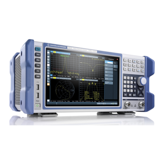
® Instrument Tour R&S ZNLE Front Panel View Instrument Tour Front Panel View This chapter describes the front panel, including all function keys and connectors. Figure 5-1: Front panel view 1 = Power key 2 = USB (2.0) connectors 3 = System keys 4 = Touchscreen 5 = Function keys 6 = Keypad... - Page 36 ® Instrument Tour R&S ZNLE Front Panel View Instrument damage caused by cleaning agents Cleaning agents contain substances such as solvents (thinners, acetone, etc.), acids, bases, or other substances. Solvents can damage the front panel labeling, plastic parts, or screens, for example. Never use cleaning agents to clean the outside of the instrument.
- Page 37 ® Instrument Tour R&S ZNLE Front Panel View 1 = Toolbar with standard application functions, e.g. print, save/open file etc. 2 = Tabs for individual channel setups 3 = Softtool panel (a.k.a. softkey bar) 4 = Window title bar with diagram-specific (trace) information 5 = Measurement results (diagram) area 6 = Channel list 7 = Diagram footer with diagram-specific information...
- Page 38 ® Instrument Tour R&S ZNLE Front Panel View 5.1.3 The front panel provides two female USB connectors (USB-A, 2.0 standard) to connect devices like a keyboard or a mouse. A memory stick can be connected to store and reload instrument settings and measurement data. The rear panel provides further USB connectors (standard 3.0), see Chap- ter 5.2.7,...
- Page 39 ® Instrument Tour R&S ZNLE Front Panel View 5.1.5 Function Keys Function keys provide access to the most common measurement settings and functions. A detailed description of the corresponding functions is provided in the User Man- ual. The labels indicated in italics (blue font color on the instrument) are not rel- evant for the R&S ZNLE.
- Page 40 ® Instrument Tour R&S ZNLE Front Panel View Function key Assigned functions [Display Lines] Configures display lines and limit lines. [Cal] Provides all functions related to system error calibration. [Single] [Channel] Creates and deletes channel setups and optimize the measure- ment process.
- Page 41 ® Instrument Tour R&S ZNLE Front Panel View Type of key Description If an alphanumeric entry has already been started, this key dele- tes the character to the left of the cursor. (BACKSPACE) ● [ENTER] Concludes the entry of dimensionless entries. The new value is accepted.
- Page 42 ® Instrument Tour R&S ZNLE Front Panel View 5.1.7.2 Navigation Keys The navigation keys can be used alternatively to the rotary knob to navigate through dialog boxes, diagrams or tables. Arrow Up/Arrow Down Keys The <arrow up> or <arrow down> keys do the following: ●...
-
Page 43: Rear Panel View
® Instrument Tour R&S ZNLE Rear Panel View Maximum input levels The maximum input levels at all test ports according to the front panel label- ing or the data sheet must not be exceeded. In addition, the maximum input voltages of the other input connectors at the rear panel must not be exceeded. - Page 44 ® Instrument Tour R&S ZNLE Rear Panel View 5 = "DVI" connector for external display 6 = "LAN" connector 7 = "USB" (3.0) connectors 5.2.1 AC Power Supply Connection and Main Power Switch An AC power supply connector and main power switch are located in a unit on the rear panel of the instrument.
- Page 45 ® Instrument Tour R&S ZNLE Rear Panel View 5.2.4 Trigger In Use the female Trigger In connector to input an external trigger or gate data. Thus, you can control the measurement using an external signal. The voltage level is 1.4 V. The typical input impedance is 10 kΩ. 5.2.5 You can connect an external monitor or other display device to the R&S ZNLE via the DVI (Digital visual interface) connector to provide an enlarged display.
-
Page 46: Trying Out The Instrument
® Trying Out the Instrument R&S ZNLE Performing Measurements Trying Out the Instrument This chapter introduces the most important functions and settings of the R&S ZNLE step by step. The complete description of the functionality and its usage is given in the R&S ZNLE User Manual. Basic instrument operation is described in Chapter 7, "Operating the Instrument",... - Page 47 ® Trying Out the Instrument R&S ZNLE Performing Measurements Measurement stages in the wizard The individual dialogs of the "S-Parameter Wizard" correspond to the typical stages of any measurement: 1. Select the test setup. 2. Define port impedances. 3. Select the measurement parameters and the diagrams. 4.
- Page 48 ® Trying Out the Instrument R&S ZNLE Performing Measurements 1. Connect the DUT between test ports 1 and 2 of the network analyzer as shown above. 2. Switch on the instrument and start the VNA application. Proceed as described in Chapter 4.1.5, "Switching the Instrument On and Off", on page 16.
- Page 49 ® Trying Out the Instrument R&S ZNLE Performing Measurements the forward transmission coefficient of the DUT. It is defined as the ratio of the transmitted wave at the DUT's output port (port no. 2) to the incident wave at the DUT's input port (port no.
- Page 50 ® Trying Out the Instrument R&S ZNLE Performing Measurements 6.1.1.3 Calibrating the Instrument Calibration (system error correction) is the process of eliminating systematic, reproducible errors from the measurement results. E.g., in the current test setup, the connecting cables between the analyzer ports and the DUT introduce an attenuation and a phase shift of the waves.
- Page 51 ® Trying Out the Instrument R&S ZNLE Performing Measurements 4. Select "Next" to proceed to the next page of the "Calibration Setting" wizard. 5. Select the test port connector type and gender (here: N 50 Ω, female, corre- sponding to a male Through standard) and the calibration kit (here: R&S ZV- Z121), then click "Start".
- Page 52 ® Trying Out the Instrument R&S ZNLE Performing Measurements 6. The "Calibration" dock widget indicates the standard measurements that make up a "Trans Norm" calibration. Select "Through (mm)" to initiate the measurement of the connected Through standard. Measuring the isolation between ports 1 and 2 is optional. Skip it for now.
- Page 53 ® Trying Out the Instrument R&S ZNLE Performing Measurements 6.1.1.4 Evaluating Data The analyzer provides various tools to optimize the display and analyze the mea- surement data. For instance, you can use markers to determine maxima and min- ima on the trace, and change the display format to obtain information about the group delay of the transmitted wave.
- Page 54 ® Trying Out the Instrument R&S ZNLE Performing Measurements Refer to section "Trace Formats" in the help system or in the user manual to learn more about the diagram properties. 6.1.2 Reflection S-Parameter Measurement In a reflection measurement, the analyzer transmits a stimulus signal to the input port of the device under test (DUT) and measures the reflected wave.
- Page 55 ® Trying Out the Instrument R&S ZNLE Performing Measurements You can also use the basic transmission test setup, e.g. if you want to mea- sure reflection and transmission parameters in parallel. ● The analyzer provides special calibration types for reflection measurements. Use the calibration wizard and select an appropriate type.
-
Page 56: Zooming Into The Display
® Trying Out the Instrument R&S ZNLE Zooming into the Display Zooming into the Display To analyze the areas around the peak levels in more detail, we will zoom into a peak. 1. Tap the "Multiple Zoom" icon in the toolbar. The icon is highlighted to indicate that zoom mode is active. -
Page 57: Saving Settings
® Trying Out the Instrument R&S ZNLE Saving Settings Figure 6-2: Zoomed display around a peak Saving Settings To restore the results of our measurements later, we will store the instrument set- tings to a file. To save the instrument settings to a file 1. - Page 58 ® Trying Out the Instrument R&S ZNLE Saving Settings Keep the default "File Type" setting "Instrument with all Channel Setups" to store the configuration of all channel setups. Figure 6-3: Saving the instrument settings to a file 4. Tap the "Save" button. The file MyMultiViewSetup.dfl is stored in the default directory C:\Users\Public\Documents\Rohde-Schwarz\ZNL\user.
-
Page 59: Printing And Saving Results
® Trying Out the Instrument R&S ZNLE Printing and Saving Results 2. Tap the "Load" icon in the toolbar. 3. In the "Load" dialog box, select the MyMultiViewSetup.dfl file in the default directory C:\Users\Public\Documents\Rohde-Schwarz\ZNL\user. 4. Tap the "Load" button. All instrument settings are restored and the display should resemble the instrument display right before the settings were stored. - Page 60 ® Trying Out the Instrument R&S ZNLE Printing and Saving Results The screenshot is stored to MyMultiViewDisplay.png. Getting Started 1323.2873.02 ─ 07...
-
Page 61: Operating The Instrument
® Operating the Instrument R&S ZNLE Understanding the Display Information Operating the Instrument This chapter provides an overview on how to work with the R&S ZNLE. Risk of touchscreen damage Inappropriate tools or excessive force can damage the touchscreen. Observe the following instructions when operating the touchscreen: ●... - Page 62 ® Operating the Instrument R&S ZNLE Understanding the Display Information 1 = Window title bar with measurement-specific (trace) information 2 = Diagram area with marker information 3 = Diagram footer with diagram-specific information Window title bar For each parameter diagram, a window is displayed with the following information in the title bar: 1 = Trace name 2 = Measured parameter...
-
Page 63: Accessing The Functionality
® Operating the Instrument R&S ZNLE Accessing the Functionality Diagram footer For each parameter diagram, a window is displayed with the following information in the footer: 1 = Channel 2 = Center frequency 3 = Power level 4 = Measurement bandwidth 5 = Span Accessing the Functionality All tasks necessary to operate the instrument can be performed using this user... - Page 64 ® Operating the Instrument R&S ZNLE Accessing the Functionality 7.2.1 Toolbar Standard functions can be performed via the icons in the toolbar on the left side of the screen. You can hide the toolbar display, e.g. when using remote control, to enlarge the display area for the measurement results ("Setup"...
- Page 65 ® Operating the Instrument R&S ZNLE Accessing the Functionality The softtools are displayed in the softkey bar of the instrument. The title area of the softkey bar displays the name of the currently opened softtool. If you close the softkey bar using its close icon, it is automatically reopened the next time a function key is pressed.
-
Page 66: Entering Data
® Operating the Instrument R&S ZNLE Entering Data 7.2.4 On-screen Keyboard The on-screen keyboard is an additional means of interacting with the instrument without having to connect an external keyboard. The on-screen keyboard display can be switched on and off as desired using the "On-Screen Keyboard"... - Page 67 ® Operating the Instrument R&S ZNLE Entering Data Transparent dialog boxes You can change the transparency of the dialog boxes to see the results in the windows behind the dialog box. Thus, you can see the effects that the changes you make to the settings have on the results immediately. To change the transparency, select the transparency icon at the top of the dialog box.
-
Page 68: Touchscreen Gestures
® Operating the Instrument R&S ZNLE Touchscreen Gestures Correcting an entry 1. Using the arrow keys, move the cursor to the right of the entry you want to delete. 2. Press the [BACKSPACE] key. The entry to the left of the cursor is deleted. 3. - Page 69 ® Operating the Instrument R&S ZNLE Touchscreen Gestures Double-tapping Tap the screen twice, in quick succession. Double-tap a diagram or the window title bar to maximize a window in the display, or to restore the original size. Dragging Move your finger from one position to another on the display, keeping your finger on the display the whole time.
- Page 70 ® Operating the Instrument R&S ZNLE Touchscreen Gestures Figure 7-4: Pinching Figure 7-5: Spreading Touch gestures in diagrams change measurement settings When you change the display using touch gestures, the corresponding measurement settings are adapted. This is different to selecting an area on the screen in zoom mode, where merely the resolution of the displayed trace points is changed temporarily (graphical zoom).
-
Page 71: Getting Help
® Operating the Instrument R&S ZNLE Getting Help Mouse operation Touch operation Drag-&-drop (= click and hold, then drag and Touch, then drag and release release) Mouse wheel to scroll up or down Swipe Dragging scrollbars to scroll up or down, left or Swipe right In (graphical) Zoom mode only: dragging the... - Page 72 ® Operating the Instrument R&S ZNLE Getting Help The "Help" dialog box "View" tab is displayed. A topic containing information about the focused screen element is displayed. If no context-specific help topic is available, a more general topic or the "Con- tent"...
- Page 73 ® Operating the Instrument R&S ZNLE Getting Help To navigate the Help, use the touchscreen. Alternatively, you can also use the navigation keys on the front panel. To search for a topic in the index The index is sorted alphabetically. You can browse the list, or search for entries in the list.
-
Page 74: Remote Control
® Operating the Instrument R&S ZNLE Remote Control Remote Control In addition to working with the R&S ZNLE interactively, located directly at the instrument, it is also possible to operate and control it from a remote PC. Various methods for remote control are supported: ●... - Page 75 ® Operating the Instrument R&S ZNLE Remote Control 7.6.2 Remote Desktop Connection Remote Desktop is a Windows application which can be used to access and con- trol the instrument from a remote computer through a LAN connection. While the instrument is in operation, the instrument screen contents are displayed on the remote computer.
-
Page 76: Collecting Information For Support
® Collecting Information for Support R&S ZNLE Collecting Information for Support If problems occur, the instrument generates error messages which in most cases will be sufficient for you to detect the cause of an error and find a remedy. Error messages are described in the "Troubleshooting" section of the user man- uals. - Page 77 ® Collecting Information for Support R&S ZNLE The file is stored as C:\Program Files\Rohde-Schwarz\Vector Network Analyzer\ZNL\ user\<inst_model>_<serial-no>_<date_and_time>.zip For example C:\Program Files\Rohde-Schwarz\Vector Network Analyzer\ZNL\ user\ZNLE3__20160803_145113.zip To create Windows event log files 1. Select the "Windows Start Button" in the bottom left corner. 2.
- Page 78 ® Collecting Information for Support R&S ZNLE Collect the error information and attach it to an email in which you describe the problem. Send the email to the customer support address for your region as listed on the Internet (http://www.customersupport.rohde-schwarz.com). Getting Started 1323.2873.02 ─...
-
Page 79: Index
® Index R&S ZNLE Index Entering data ........... 66 Error log ...........76 Alphanumeric parameters ....... 67 ESD ............12 Application cards ........10 Evaluation of data ........53 Application notes ........10 External monitor Arrow keys ..........42 Connectors ......... 45 Basic Measurement Examples Firmware updates see User Manual ........6 see User Manual ......... - Page 80 ® Index R&S ZNLE Keyboard Power supply On-screen ........... 66 Connector ........... 44 Keypad Printer configuration Overview ..........40 see user Manual ......... 11 Printer setup see User Manual .........33 Printing Trying out ..........59 Configuration ........26 Configuration - see user Manual ..11 Connector ...........
- Page 81 ® Index R&S ZNLE Time Setting ..........33 Toolbar Overview ..........64 Touchscreen Overview ..........36 Transmission measurement (example) ... 47 Trigger In Connector ........... 45 Trying out Prerequisites ........46 Connector ........... 45 Connectors ......... 38 Virus protection ........18 White papers ...........
Need help?
Do you have a question about the ZNLE Series and is the answer not in the manual?
Questions and answers