R&S ZNA26 Getting Started
Vector network analyzers
Hide thumbs
Also See for ZNA26:
- Getting started (75 pages) ,
- User manual (1605 pages) ,
- User manual (1709 pages)
Table of Contents
Advertisement
Quick Links
Advertisement
Table of Contents

Related Manuals for R&S ZNA26


Summary of Contents for R&S ZNA26
- Page 1 ® R&S Vector Network Analyzers Getting Started (;ÜÎÆ2) 1178645602 Version 18...
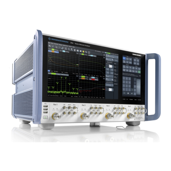
- Page 2 ZNA vector network analyzer models: ● ® R&S ZNA26, 10 MHz to 26.5 GHz, 2 test ports, 3.5 mm (m) connectors, order no. 1332.4500K22 ● ® R&S ZNA26, 10 MHz to 26.5 GHz, 4 test ports, 3.5 mm (m) connectors, order no. 1332.4500K24 ●...
-
Page 3: Table Of Contents
® Contents R&S Contents 1 Safety and regulatory information............7 Safety instructions......................7 Warning messages in the documentation..............10 Korea certification class A..................10 2 Documentation overview..............11 Getting started manual....................11 User manual and help....................11 Service manual......................11 Instrument security procedures................12 Printed safety instructions..................12 Data sheets and brochures.................. - Page 4 ® Contents R&S 3.11.5 Connecting a LAN cable....................23 3.11.6 Connecting a USB cable for remote control..............23 4 Instrument tour..................24 Front panel........................24 4.1.1 Touchscreen........................25 4.1.2 Status LEDs........................28 4.1.3 Standby key........................28 4.1.4 Front panel connectors....................29 Rear panel........................31 5 Operating the instrument..............33 Manual operation......................
- Page 5 ® Contents R&S 5.7.2 Setting the sweep range....................57 5.7.3 Reference value and position..................58 5.7.4 Auto scale........................58 5.7.5 Circular diagrams......................59 5.7.6 Set by marker........................59 5.7.7 Enlarging a diagram...................... 60 6 Performing measurements..............62 Transmission S-parameter measurement..............62 6.1.1 Connecting the instrument for transmission measurements......... 62 6.1.2 Selecting the sweep range and other parameters............
- Page 6 ® Contents R&S Getting Started 1178.6456.02 ─ 18...
-
Page 7: Safety And Regulatory Information
® Safety and regulatory information R&S Safety instructions 1 Safety and regulatory information The product documentation helps you use the product safely and efficiently. Follow the instructions provided here and in the following chapters. Intended use The product is intended for the development, production and verification of electronic components and devices in industrial, administrative, and laboratory environments. - Page 8 ® Safety and regulatory information R&S Safety instructions move or carry the product. Do not lift by the accessories mounted on the product. Accessories are not designed to carry the weight of the product. To move the product safely, you can use lifting or transporting equipment such as lift trucks and forklifts.
- Page 9 ® Safety and regulatory information R&S Safety instructions ● Only use the power cable delivered with the product. It complies with country-spe- cific safety requirements. Only insert the plug into an outlet with protective conduc- tor terminal. ● Only use intact cables and route them carefully so that they cannot be damaged. Check the power cables regularly to ensure that they are undamaged.
-
Page 10: Warning Messages In The Documentation
® Safety and regulatory information R&S Korea certification class A 1.2 Warning messages in the documentation A warning message points out a risk or danger that you need to be aware of. The sig- nal word indicates the severity of the safety hazard and how likely it will occur if you do not follow the safety precautions. -
Page 11: Documentation Overview
® Documentation overview R&S Service manual 2 Documentation overview This section provides an overview of the R&S ZNA user documentation. Unless speci- fied otherwise, you find the documents on the R&S ZNA product page at: https://www.rohde-schwarz.com/manual/ZNA 2.1 Getting started manual Introduces the R&S ZNA and describes how to set up and start working with the prod- uct. -
Page 12: Instrument Security Procedures
® Documentation overview R&S Application notes, application cards, white papers, etc. 2.4 Instrument security procedures Deals with security issues when working with the R&S ZNA in secure areas. It is avail- able for download on the Internet. 2.5 Printed safety instructions Provides safety information in many languages. -
Page 13: Preparing For Use
® Preparing for use R&S Choosing the operating site 3 Preparing for use Here, you can find basic information about setting up the product for the first time. 3.1 Lifting and carrying The carrying handles are designed to lift or carry the instrument. Do not apply exces- sive external force to the handles. -
Page 14: Setting Up The Product
® Preparing for use R&S Setting up the product If class A equipment causes radio disturbances, take appropriate measures to eliminate them. 3.4 Setting up the product See also: ● "Setting up the product" on page 8 ● "Intended use" on page 7 3.4.1 Placing the product on a bench top To place the product on a bench top... -
Page 15: Mounting The Product In A Rack
® Preparing for use R&S Considerations for test setup ● Do not place the product next to heat-generating equipment such as radiators or other products. 3.4.2 Mounting the product in a rack To prepare the rack 1. Observe the requirements and instructions in "Setting up the product"... -
Page 16: Connecting The Analyzer To The Ac Supply
® Preparing for use R&S Connecting the analyzer to the AC supply Regarding length and quality, the following requirements have to be met for cable that are directly connected to the R&S ZNA: Table 3-1: Cable Requirements Cable Type (Connector) Requirement RF cables (PORT 1, ..., PORT N) Double shielded... -
Page 17: Switching The Instrument On And Off
® Preparing for use R&S Switching the instrument on and off The network analyzer is automatically adapted to the AC supply voltage, which must be in the range of 100 V to 240 V at 50 Hz to 60 Hz. A line frequency of 400 Hz is also supported. -
Page 18: Standby And Ready State
® Preparing for use R&S Windows operating system 2. If desired, set the AC power switch to position O (Off). To disconnect from power The R&S ZNA is in standby state. 1. NOTICE! Risk of data loss. If you disconnect the product from power when it is in the ready state, you can lose settings and data. - Page 19 ® Preparing for use R&S Windows operating system Modifications of the operating system The operating system is adapted to the network analyzer. To avoid impairment of instrument functions, only change the settings described in this manual. Existing soft- ware must be modified only with update software released by Rohde & Schwarz. Like- wise, only programs authorized by Rohde &...
-
Page 20: Minimizing The Vna Application
® Preparing for use R&S Minimizing the VNA application background ("on-access" mode) on Windows-based instruments, due to potentially degrading instrument performance. However, Rohde & Schwarz does recommend run- ning it during non-critical hours. For details and recommendations, see the following Rohde & Schwarz white paper: ●... -
Page 21: Connecting External Accessories
® Preparing for use R&S Connecting external accessories 3.11 Connecting external accessories The analyzer's standard PC interfaces (Monitor, USB, LAN) can be used to connect various accessories: ● An external monitor displays the Windows ® desktop plus the vector network ana- lyzer (VNA) application windows. -
Page 22: Connecting A Mouse
® Preparing for use R&S Connecting external accessories ® To access Windows , use the button in the toolbar of the application window. 3.11.3 Connecting a mouse A USB mouse can be connected to any of the USB connectors. After being auto-detec- ted by the operating system, it can safely be disconnected and reconnected even dur- ing measurements. -
Page 23: Connecting A Lan Cable
® Preparing for use R&S Connecting external accessories Printer configuration Use the "Printer Setup" dialog of the firmware (System – [File Print] > "Print" > ® "Print...") or the Windows printer management to configure the printer properties and printing preferences. 3.11.5 Connecting a LAN cable A LAN cable can be connected to the LAN connector on the rear panel of the analyzer. -
Page 24: Instrument Tour
® Instrument tour R&S Front panel 4 Instrument tour This chapter gives an overview of the control elements and connectors of the R&S ZNA and gives all information that is necessary to put the instrument into opera- tion and connect external devices. 4.1 Front panel The front panel of a R&S ZNA consists of a large-scale capacitive touchscreen and the test port area below it. -
Page 25: Touchscreen
® Instrument tour R&S Front panel 4.1.1 Touchscreen The touchscreen is split into two parts: the application window with diagrams and soft- tools on the left, and the control window with its (virtual) function keys and data entry controls on the right. User interaction is touch-only, i.e. all hardkeys commonly used in Rohde &... - Page 26 ® Instrument tour R&S Front panel ● Refer to the description of the "Display" softtool (System – [Display]) in the user manual or help system to learn how to customize the screen. 4.1.1.2 Control window: function keys Most of the (virtual) keys in the upper part of the control window call up a related soft- tool of the analyzer GUI.
- Page 27 ® Instrument tour R&S Front panel – Choose the measurements to be performed on a selected DUT. The analyzer firmware then helps you to set up the channels accordingly. ● [Applic]: external software tools and optional extensions of the analyzer firmware. ●...
-
Page 28: Status Leds
® Instrument tour R&S Front panel 4.1.2 Status LEDs Multi-color LEDs, indicating various HW and FW states: ● Ext. Ref. Indicates whether an external reference clock is used. – Off: the internal reference clock is used – Green: the R&S ZNA is synchronized to an external reference clock –... -
Page 29: Front Panel Connectors
The test ports and three USB connectors are located on the front panel of the R&S ZNA. 4.1.4.1 Test ports Numbered connectors: ● 3.5 mm male for R&S ZNA26 ● 2.92 mm (K) or 2.4 mm male for R&S ZNA43 ● 2.4 mm male for R&S ZNA50 ●... - Page 30 ® Instrument tour R&S Front panel 4.1.4.2 Direct generator and receiver access Hardware options R&S ZNA<frequency>-B16 "Direct Generator/Receiver Access", provide 3 pairs of SMA connectors for each test port, where <frequency> corresponds to the network analyzer type. For detailed ordering information, refer to the product brochure.
-
Page 31: Rear Panel
® Instrument tour R&S Rear panel 4.2 Rear panel This section gives an overview of the rear panel elements of the network analyzer. Table 4-1: Rear panel elements available on all instruments Index Label Description System Drive Removable system drive of the R&S ZNA, containing all software (including the operating system and the VNA application) and data. - Page 32 ® Instrument tour R&S Rear panel Index Label Description External Handler IO Used to connect an external Handler I/O (option R&S ZNBT-Z14), providing a Centronics 36 input/output connector. Not yet supported. External Data Logger Digital interface for data streaming. Requires "Data Streaming Memory" option R&S ZNA-B7 (not yet available). SMA connector for external reference clock input or output.
-
Page 33: Operating The Instrument
® Operating the instrument R&S Manual operation 5 Operating the instrument The following sections describe the basics of manual operation, i.e. how to access instrument functions and settings via the analyzer GUI. Manual operation is particularly useful for getting to know the instrument and for trouble shooting. Manual and remote control of the instrument Manual control of the R&S ZNA is possible either via its touchscreen (without using a mouse and/or keyboard), via locally connected monitor + mouse + keyboard (see... - Page 34 ® Operating the instrument R&S Manual operation Customizing the screen The contents of the screen and the size and position of many display and control ele- ments are not fixed. You can display or hide most elements. You can also drag and drop traces and info fields.
- Page 35 ® Operating the instrument R&S Manual operation 4. Select a control element, e.g. "a1 Src Port 1". The diagram immediately reflects your selection. The active trace shows the mea- surement results for the selected measured quantity. A control element with three dots (e.g. System – [Setup] > "Setup" > "System Con- fig...") opens a dialog, containing a group of related settings, a wizard or additional information.
- Page 36 ® Operating the instrument R&S Manual operation Using the menu bar The menu bar at the bottom of the application screen provides alternative access to all instrument functions. To repeat the measured quantity selection described above, ► Select Trace – [Meas] > "S-Params" > "Wave" > "a1 Src Port 1". The diagram immediately reflects your selection.
-
Page 37: Control Elements Of The Application Window
® Operating the instrument R&S Control elements of the application window 2. Select "a1 Src Port 2". 5.2 Control elements of the application window The application window of the analyzer provides all control elements for the measure- ments and contains the diagrams for the results. There are several alternative ways for accessing an instrument function: ●... -
Page 38: Title Bar
® Operating the instrument R&S Control elements of the application window These methods are described in more detail in the following sections. 5.2.1 Title bar By default, the analyzer GUI is shown in full screen mode, covering the whole screen and hiding the Windows taskbar. -
Page 39: Softtools
® Operating the instrument R&S Control elements of the application window These icons represent the undo and redo actions that are also available via the menu bar items "System" > "Undo" / "Redo". Undo reverses the last action, redo reverses the last undo action (if possi- ble). -
Page 40: Menu Bar
® Operating the instrument R&S Control elements of the application window Figure 5-2: Scale softtool A softtool is a tabbed panel with a close icon. When the softtool is closed, the close icon is replaced by a "hamburger" icon. The latter allows you to reopen the softtool. Some controls on the softtool tabs allow you to read and modify settings (e.g. -
Page 41: Menu Structure
® Operating the instrument R&S Control elements of the application window ● The "Channel" menu provides all channel settings and activates, modifies or stores different channels. ● The "Display" menu provides all display settings and the functions for activating, modifying and arranging different diagrams. ●... -
Page 42: Hardkey Panel
® Operating the instrument R&S Control elements of the application window Example: "Max" sets the active marker to the maximum of the active trace. 5.2.6 Hardkey panel The (virtual) "Hard Key" panel displays the control window's function keys inside the main application window. -
Page 43: Status Bar
® Operating the instrument R&S Touchscreen gestures 5.2.7 Status bar The status bar shows ● the active channel ● the current channel's sweep averaging counter (e.g. "Ch<i>: Avg 9/10"), or "Ch<i>: Avg None" if averaging is disabled ● the progress of the sweep The progress bar also shows when the R&S ZNA prepares a sweep with new channel settings ●... - Page 44 ® Operating the instrument R&S Touchscreen gestures Double-tap a diagram to maximize it or to restore its original size. Dragging Move your finger from one position to another on the display, keeping your finger on the display the whole time. By dragging your finger over a table or diagram you can pan the displayed area of the table or diagram to show results that were previously out of view.
-
Page 45: Working With Dialogs
® Operating the instrument R&S Working with dialogs ● In stimulus zoom mode, spreading and pinging is disabled by default. Only while "Stim. Zoom Select" is active (toolbar icon or softtool button is toggled on), you can use spreading and pinching to modify the sweep area and/or the vertical scaling. Mouse vs. -
Page 46: Handling Diagrams, Traces, And Markers
® Operating the instrument R&S Handling diagrams, traces, and markers All dialogs are operated in a similar way. ● To open a dialog, select a softtool button with three dots appearing in its label (e.g. "Start... (Manual)"). ● The title bar of each dialog contains some convenience functions: –... -
Page 47: Adding New Traces And Diagrams
® Operating the instrument R&S Handling diagrams, traces, and markers trace. The following section presents some of the graphical tools the R&S ZNA pro- vides for trace and marker handling. For further reference Refer to chapter "Concepts and Features" in the R&S ZNA Help or in the User Manual to learn more about traces, channels, and screen elements. - Page 48 ® Operating the instrument R&S Handling diagrams, traces, and markers 3. In the dialog box that is opened when you release the "New Trace" icon, select the S-parameter to be measured. For a four-port analyzer: The R&S ZNA generates a new trace for the selected S-parameter. Getting Started 1178.6456.02 ─...
-
Page 49: Adding New Markers
® Operating the instrument R&S Handling diagrams, traces, and markers Alternative control elements To measure a different quantity, select Trace – [Meas]. Drag and drop a softkey repre- senting a measured quantity to create a trace. Or simply select another softkey to change the measured quantity of the active trace. -
Page 50: Deleting Display Elements
® Operating the instrument R&S Handling diagrams, traces, and markers Active trace, alternative control elements The trace line of the active trace in the upper part of the diagram is highlighted. If the diagram contains several traces, first activate the target trace, then add the marker. The Trace –... -
Page 51: Entering Data
® Operating the instrument R&S Entering data Table 5-2: Drag and drop functionality for various screen elements Screen element Action Drag and drop... Diagram Create Chapter 5.5.1, "Adding new traces and diagrams", on page 47 Resize Separator between adjacent diagrams Delete Chapter 5.5.3, "Deleting display elements",... -
Page 52: Using The Numeric Editor
® Operating the instrument R&S Entering data Chapter 4.1.1.3, "Control window: data entry panel", on page 27. In single-window mode (System – [Display] > "Config" > "Single Window Mode") only the application window is shown, with its virtual Hardkey panel enabled. -
Page 53: Using The Analyzer's On-Screen Keyboard
® Operating the instrument R&S Entering data 2. Use the buttons in the numeric keypad to compose the numeric input value. 3. If desired, select a "Step Size" and use the cursor up/down buttons to increment/ decrement the current value. If a marker is active, you can also set the numeric value to the current marker value ("Set to Marker"). -
Page 54: Using The Windows ® On-Screen Keyboard
® Operating the instrument R&S Entering data For the following procedure, we assume single-window mode. 1. Activate a character data input field in a softtool or a dialog. 2. Double-tap/click the input field to open the on-screen keyboard. 3. Select character buttons to compose the input string. 4. -
Page 55: Scaling Diagrams
® Operating the instrument R&S Scaling diagrams 2. Select "External Tools" 3. Select "Screen Keyboard". 5.7 Scaling diagrams The analyzer provides various tools for customizing the diagrams and for setting the sweep range. Choose the method that is most convenient for you. 5.7.1 Using the graphical zoom The graphical zoom function magnifies a rectangular portion of the diagram (zoom win- dow) to fill the entire diagram area. - Page 56 ® Operating the instrument R&S Scaling diagrams The zoomed view shows the selected rectangle, scaled in both horizontal and verti- cal direction. In general, the zoom window covers only a part of the sweep range; the horizontal distance between the sweep points increases. The reduced display range is indicated in an additional zoom line in the channel info area.
-
Page 57: Setting The Sweep Range
® Operating the instrument R&S Scaling diagrams Alternative settings ● The Trace – [Scale] > "Zoom" softtool tab allows you to define the displayed zoom range numerically. It can also be opened from the menu of the "Zoom Config" toolbar icon. ●... -
Page 58: Reference Value And Position
® Operating the instrument R&S Scaling diagrams To change the sweep range of the active channel, use one of the following methods: ● Use the [Start], [Stop], [Center], and [Span] function keys from the Stimulus sec- tion. ● Double-tap (with a mouse: double-click) the "Start" or "Stop" label in the channel list. -
Page 59: Circular Diagrams
® Operating the instrument R&S Scaling diagrams ● Select "Auto Scale Trace" or "Auto Scale Diagram" from the "Trace" > "Scale" menu. 5.7.5 Circular diagrams The radial scale of a circular diagram ("Polar", "Smith" or "Inverted Smith") can be changed with a single linear parameter, the "Ref Value". The reference value defines the radius of the outer circumference. -
Page 60: Enlarging A Diagram
® Operating the instrument R&S Scaling diagrams Set "Start" and "Stop" values in the diagram: 1. Create two normal markers, e.g. the markers "Mkr 1" (default label "M1") and "Mkr 2" (default label "M2"). Chapter 5.5.2, "Adding new markers", on page 49. 2. - Page 61 ® Operating the instrument R&S Scaling diagrams Use the context menu of the diagram, the System – [Display] key or the "Display" menu to access the display settings. Getting Started 1178.6456.02 ─ 18...
-
Page 62: Performing Measurements
® Performing measurements R&S Transmission S-parameter measurement 6 Performing measurements This chapter takes you through a sample session with a R&S ZNA network analyzer and describes basic operation tasks. Prerequisite The instrument is set up, connected to the mains system, and started up as described Chapter 3, "Preparing for use", on page 13. -
Page 63: Selecting The Sweep Range And Other Parameters
® Performing measurements R&S Transmission S-parameter measurement 1. Connect the DUT between test ports 1 and 2 of the network analyzer as shown above. 2. Use the [Preset] key to restore a well-defined instrument state. The analyzer is now set to its default state. The default measured quantity is the transmission S-parameter S Select Trace –... -
Page 64: Calibrating The Instrument
® Performing measurements R&S Transmission S-parameter measurement The R&S ZNA automatically adjusts its internal source and receiver to the selected measured quantities: For an S measurement, a stimulus signal (termed a ) is trans- mitted at the analyzer port no. 1; the transmitted wave (termed b ) is measured at port 2. - Page 65 ® Performing measurements R&S Transmission S-parameter measurement Due to the R&S ZNA's calibration wizard, calibration is a straightforward, guided proc- ess. 1. Replace the DUT by the Through standard of your calibration kit. Make sure to dis- connect all calibration units. 2.
- Page 66 ® Performing measurements R&S Transmission S-parameter measurement 8. Tap "Start Cal". 9. The calibration dock widget indicates the standard measurements that make up a "Trans Norm" calibration. Select "Through (mm)" to initiate the measurement of the connected Through stan- dard. Measuring the isolation between ports 1 and 2 is optional. Skip it for now. The analyzer performs a calibration sweep for the measured quantity S .
-
Page 67: Evaluating Data
® Performing measurements R&S Transmission S-parameter measurement To proceed with the measurement, remove the Through standard and connect the DUT again. 6.1.4 Evaluating data The analyzer provides various tools to optimize the display and analyze the measure- ment data. For instance, you can use markers to determine maxima and minima on the trace, and change the display format to obtain information about the group delay of the transmitted wave. -
Page 68: Saving And Printing Data
® Performing measurements R&S Transmission S-parameter measurement Refer to the information on trace formats in the help system or in the user manual to learn more about the diagram properties. 6.1.5 Saving and printing data The analyzer provides standard functions for saving measurement settings and for saving or printing the results. -
Page 69: Reflection S-Parameter Measurement
® Performing measurements R&S Reflection S-parameter measurement 7. In the "Save" dialog: a) Select a file location ("Look in:"). b) Enter a name for the recall set file ("File name:"). c) Select "Save". The analyzer saves the active recall set, containing channel, stimulus and trace settings, to a znxml file. - Page 70 ® Performing measurements R&S Reflection S-parameter measurement ● Some of the trace formats are particularly suited for reflection measurements. For instance, you can display the measured reflection coefficient S in a Smith chart to obtain the complex input impedance at port 1. Proceed as described in Chapter 3.7, "Switching the instrument on and off",...
-
Page 71: Administrative Tasks
® Administrative tasks R&S Firmware installation 7 Administrative tasks This chapter describes some topics that are only needed occasionally, or if a special instrument configuration is required. 7.1 Firmware installation Upgrade versions of the analyzer firmware are supplied as single executable setup files (*.exe). -
Page 72: Remote Operation In A Lan
® Administrative tasks R&S Remote operation in a LAN 7.2 Remote operation in a LAN A LAN connection is used to integrate the analyzer into a home/company network. LAN connectivity offers several applications, e.g.: ● Transfer data between a controller and the analyzer, e.g. to run a remote control program. - Page 73 ® Administrative tasks R&S Remote operation in a LAN 2. Use the Windows icon in the toolbar (or the Windows key on an external keyboard) ® to access Windows 3. Open the "Control Panel" > "Network and Sharing Center" > "Change adapter set- tings"...
-
Page 74: Using Computer Names
® Administrative tasks R&S Remote operation in a LAN 7.2.2 Using computer names In a LAN that uses a DNS server (Domain Name System server), each PC or instru- ment connected in the LAN can be accessed via an unambiguous computer name instead of the IP address. -
Page 75: Remote Desktop Connection
® Administrative tasks R&S Remote operation in a LAN 7.2.3 Remote Desktop connection ® Remote Desktop is a Windows application which you can use to access and control the analyzer from a remote computer through a LAN connection. While the measure- ment is running, the analyzer screen contents are displayed on the remote computer, and Remote Desktop provides access to all applications, files, and network resources of the analyzer. - Page 76 ® Administrative tasks R&S Remote operation in a LAN ● Select "Turn Windows Firewall on or off" to enable or disable the firewall. Confirm the user account control message to allow the desired changes (see Fig- ® 7-1). For detailed information about the firewall, refer to the Windows Help.
-
Page 77: Contacting Customer Support
® Contacting customer support R&S 8 Contacting customer support Technical support – where and when you need it For quick, expert help with any Rohde & Schwarz product, contact our customer sup- port center. A team of highly qualified engineers provides support and works with you to find a solution to your query on any aspect of the operation, programming or applica- tions of Rohde &... -
Page 78: Index
® Index R&S Index Function keys ..............26 Channel section ............26 AC supply ................16 Stimulus section ............26 Accessories (connect) ............21 System section ............26 Administrative tasks ............71 Trace section .............. 26 Application cards ............... 12 Application notes ............... - Page 79 ® Index R&S Option Toolbar ................38 R&S ZNA-B4 ............... 18 Touchscreen ..............25 R&S ZNA-B7 ............... 31 Trace ................. 46 Trace keys ................. 26 R&S ZNA-B15 (RFFE GPIO Interface) ....... 32 Transmission measurement (example) ......62 R&S ZNA-B19 ............. 31 Trigger In R&S ZNA-B26 (Direct IF Access) .......
Need help?
Do you have a question about the ZNA26 and is the answer not in the manual?
Questions and answers