Table of Contents
Advertisement
Quick Links
Advertisement
Chapters
Table of Contents

Related Manuals for R&S ZNL Series


Summary of Contents for R&S ZNL Series
- Page 1 ® R&S ZNL/ZNLE Vector Network Analyzers User Manual (;ÜÉÐ2) 1178596602...
- Page 2 This manual applies to the following vector network analyzer models: ● ® R&S ZNL3, 5 kHz to 3 GHz, 2 ports, N(f) connectors, order no. 1323.0012.03 ● ® R&S ZNL6, 5 kHz to 6 GHz, 2 ports, N(f) connectors, order no. 1323.0012.06 ●...
- Page 3 Basic Safety Instructions Always read through and comply with the following safety instructions! All plants and locations of the Rohde & Schwarz group of companies make every effort to keep the safety standards of our products up to date and to offer our customers the highest possible degree of safety. Our products and the auxiliary equipment they require are designed, built and tested in accordance with the safety standards that apply in each case.
- Page 4 Basic Safety Instructions Symbol Meaning Symbol Meaning Caution ! Hot surface Alternating current (AC) Protective conductor terminal Direct/alternating current (DC/AC) To identify any terminal which is intended for connection to an external conductor for protection against electric shock in case of a fault, or the terminal of a protective earth Earth (Ground) Class II Equipment...
- Page 5 Basic Safety Instructions Operating states and operating positions The product may be operated only under the operating conditions and in the positions specified by the manufacturer, without the product's ventilation being obstructed. If the manufacturer's specifications are not observed, this can result in electric shock, fire and/or serious personal injury or death. Applicable local or national safety regulations and rules for the prevention of accidents must be observed in all work performed.
- Page 6 Basic Safety Instructions 6. The product may be operated only from TN/TT supply networks fuse-protected with max. 16 A (higher fuse only after consulting with the Rohde & Schwarz group of companies). 7. Do not insert the plug into sockets that are dusty or dirty. Insert the plug firmly and all the way into the socket provided for this purpose.
- Page 7 Basic Safety Instructions 2. Before you move or transport the product, read and observe the section titled "Transport". 3. As with all industrially manufactured goods, the use of substances that induce an allergic reaction (allergens) such as nickel cannot be generally excluded. If you develop an allergic reaction (such as a skin rash, frequent sneezing, red eyes or respiratory difficulties) when using a Rohde &...
- Page 8 Basic Safety Instructions 2. Adjustments, replacement of parts, maintenance and repair may be performed only by electrical experts authorized by Rohde & Schwarz. Only original parts may be used for replacing parts relevant to safety (e.g. power switches, power transformers, fuses). A safety test must always be performed after parts relevant to safety have been replaced (visual inspection, protective conductor test, insulation resistance measurement, leakage current measurement, functional test).
- Page 9 Instrucciones de seguridad elementales 3. If you use the product in a vehicle, it is the sole responsibility of the driver to drive the vehicle safely and properly. The manufacturer assumes no responsibility for accidents or collisions. Never use the product in a moving vehicle if doing so could distract the driver of the vehicle.
- Page 10 Instrucciones de seguridad elementales Además queda en la responsabilidad del usuario utilizar el producto en la forma debida. Este producto está destinado exclusivamente al uso en la industria y el laboratorio o, si ha sido expresamente autorizado, para aplicaciones de campo y de ninguna manera deberá ser utilizado de modo que alguna persona/cosa pueda sufrir daño.
- Page 11 Instrucciones de seguridad elementales Símbolo Significado Símbolo Significado Conexión a tierra El aparato está protegido en su totalidad por un aislamiento doble (reforzado) Conexión a masa Distintivo de la UE para baterías y acumuladores Más información en la sección "Eliminación/protección del medio ambiente", punto 1.
- Page 12 Instrucciones de seguridad elementales Estados operativos y posiciones de funcionamiento El producto solamente debe ser utilizado según lo indicado por el fabricante respecto a los estados operativos y posiciones de funcionamiento sin que se obstruya la ventilación. Si no se siguen las indicaciones del fabricante, pueden producirse choques eléctricos, incendios y/o lesiones graves con posible consecuencia de muerte.
- Page 13 Instrucciones de seguridad elementales integran productos sin interruptor en bastidores o instalaciones, se deberá colocar el interruptor en el nivel de la instalación. 5. No utilice nunca el producto si está dañado el cable de conexión a red. Compruebe regularmente el correcto estado de los cables de conexión a red.
- Page 14 Instrucciones de seguridad elementales 17. No utilice el producto en condiciones en las que pueda producirse o ya se hayan producido condensaciones sobre el producto o en el interior de éste, como p. ej. al desplazarlo de un lugar frío a otro caliente.
- Page 15 Instrucciones de seguridad elementales pueden causar perturbaciones radioeléctricas en entornos residenciales debido a posibles perturbaciones guiadas o radiadas. En este caso, se le podrá solicitar al operador que tome las medidas adecuadas para eliminar estas perturbaciones. Aparato de clase B: Aparato adecuado para su uso en entornos residenciales, así...
- Page 16 Instrucciones de seguridad elementales 8. En caso de devolver baterías de litio a las filiales de Rohde & Schwarz, debe cumplirse las normativas sobre los modos de transporte (IATA-DGR, código IMDG, ADR, RID). Transporte 1. El producto puede tener un peso elevado. Por eso es necesario desplazarlo o transportarlo con precaución y, si es necesario, usando un sistema de elevación adecuado (p.
-
Page 17: Grundlegende Sicherheitshinweise
Grundlegende Sicherheitshinweise Lesen und beachten Sie unbedingt die nachfolgenden Anweisungen und Sicherheitshinweise! Alle Werke und Standorte der Rohde & Schwarz Firmengruppe sind ständig bemüht, den Sicherheitsstandard unserer Produkte auf dem aktuellsten Stand zu halten und unseren Kunden ein höchstmögliches Maß an Sicherheit zu bieten. Unsere Produkte und die dafür erforderlichen Zusatzgeräte werden entsprechend der jeweils gültigen Sicherheitsvorschriften gebaut und geprüft. - Page 18 Grundlegende Sicherheitshinweise Symbole und Sicherheitskennzeichnungen Symbol Bedeutung Symbol Bedeutung Achtung, allgemeine Gefahrenstelle EIN-/AUS (Versorgung) Produktdokumentation beachten Vorsicht beim Umgang mit Geräten mit hohem Stand-by-Anzeige Gewicht Gefahr vor elektrischem Schlag Gleichstrom (DC) Warnung vor heißer Oberfläche Wechselstrom (AC) Schutzleiteranschluss Gleichstrom/Wechselstrom (DC/AC) Erdungsanschluss Gerät entspricht den Sicherheits- anforderungen an die Schutzklasse II...
- Page 19 Grundlegende Sicherheitshinweise Signalworte und ihre Bedeutung Die folgenden Signalworte werden in der Produktdokumentation verwendet, um vor Risiken und Gefahren zu warnen. kennzeichnet eine unmittelbare Gefährdung mit hohem Risiko, die Tod oder schwere Körperverletzung zur Folge haben wird, wenn sie nicht vermieden wird.
- Page 20 Grundlegende Sicherheitshinweise Elektrische Sicherheit Werden die Hinweise zur elektrischen Sicherheit nicht oder unzureichend beachtet, kann dies elektrischen Schlag, Brand und/oder schwere Verletzungen von Personen, unter Umständen mit Todesfolge, verursachen. 1. Vor jedem Einschalten des Produkts ist sicherzustellen, dass die am Produkt eingestellte Nennspannung und die Netznennspannung des Versorgungsnetzes übereinstimmen.
- Page 21 Grundlegende Sicherheitshinweise 12. Wird ein Produkt ortsfest angeschlossen, ist die Verbindung zwischen dem Schutzleiteranschluss vor Ort und dem Geräteschutzleiter vor jeglicher anderer Verbindung herzustellen. Aufstellung und Anschluss darf nur durch eine Elektrofachkraft erfolgen. 13. Bei ortsfesten Geräten ohne eingebaute Sicherung, Selbstschalter oder ähnliche Schutzeinrichtung muss der Versorgungskreis so abgesichert sein, dass alle Personen, die Zugang zum Produkt haben, sowie das Produkt selbst ausreichend vor Schäden geschützt sind.
- Page 22 Grundlegende Sicherheitshinweise 5. Bei bestimmten Produkten, z.B. HF-Funkanlagen, können funktionsbedingt erhöhte elektromag- netische Strahlungen auftreten. Unter Berücksichtigung der erhöhten Schutzwürdigkeit des unge- borenen Lebens müssen Schwangere durch geeignete Maßnahmen geschützt werden. Auch Träger von Herzschrittmachern können durch elektromagnetische Strahlungen gefährdet sein. Der Arbeitgeber/Betreiber ist verpflichtet, Arbeitsstätten, bei denen ein besonderes Risiko einer Strahlen- exposition besteht, zu beurteilen und zu kennzeichnen und mögliche Gefahren abzuwenden.
- Page 23 Grundlegende Sicherheitshinweise 3. Zellen oder Batterien dürfen nicht kurzgeschlossen werden. Zellen oder Batterien dürfen nicht gefahrbringend in einer Schachtel oder in einem Schubfach gelagert werden, wo sie sich gegenseitig kurzschließen oder durch andere leitende Werkstoffe kurzgeschlossen werden können. Eine Zelle oder Batterie darf erst aus ihrer Originalverpackung entnommen werden, wenn sie verwendet werden soll.
- Page 24 Grundlegende Sicherheitshinweise 3. Werden Produkte oder ihre Bestandteile über den bestimmungsgemäßen Betrieb hinaus mechanisch und/oder thermisch bearbeitet, können ggf. gefährliche Stoffe (schwermetallhaltiger Staub wie z.B. Blei, Beryllium, Nickel) freigesetzt werden. Die Zerlegung des Produkts darf daher nur von speziell geschultem Fachpersonal erfolgen. Unsachgemäßes Zerlegen kann Gesundheitsschäden hervorrufen.
- Page 25 Consignes de sécurité fondamentales Lisez et respectez impérativement les instructions et consignes de sécurité suivantes Les usines et sites du groupe Rohde & Schwarz veillent à la conformité des produits du groupe avec les normes de sécurité en vigueur dans un souci constant de garantir aux clients le plus haut niveau de sécurité...
- Page 26 Consignes de sécurité fondamentales Symboles et marquages de sécurité Symbole Signification Symbole Signification Avis, source générale de danger MARCHE / ARRET (tension d’alimentation) Se référer à la documentation produit Attention lors de la manipulation d’appareils Indicateur de veille ayant un poids élevé Risque de choc électrique Courant continu (CC) Avertissement, surface chaude...
- Page 27 Consignes de sécurité fondamentales Mots d’alerte et significations Les mots d’alerte suivants sont utilisés dans la documentation produit pour avertir des risques et dangers. Indique une situation dangereuse immédiate qui, si elle n’est pas évitée, comporte un risque élevé de blessures graves ou mortelles.
- Page 28 Consignes de sécurité fondamentales Sécurité électrique Si les consignes relatives à la sécurité électrique ne sont pas ou sont insuffisamment respectées, il peut s’ensuivre des chocs électriques, des incendies et/ou des blessures graves pouvant éventuellement entraîner la mort. 1. Avant chaque mise sous tension du produit, il faut s’assurer que la tension nominale réglée sur le produit correspond à...
- Page 29 Consignes de sécurité fondamentales 12. Si un produit est connecté de façon stationnaire, établir avant toute autre connexion le raccordement du conducteur de protection local et du conducteur de protection du produit. L’installation et le raccordement ne peuvent être effectués que par un électricien ou électronicien qualifié. 13.
- Page 30 Consignes de sécurité fondamentales 5. Selon les fonctions, certains produits, tels que des systèmes de radiocommunication RF, peuvent produire des niveaux élevés de rayonnement électromagnétique. Étant donné la vulnérabilité de l’enfant à naître, les femmes enceintes doivent être protégées par des mesures appropriées. Les porteurs de stimulateurs cardiaques peuvent également être menacés par les rayonnements électromagnétiques.
- Page 31 Consignes de sécurité fondamentales Batteries et accumulateurs/cellules Si les instructions concernant les batteries et accumulateurs/cellules ne sont pas ou sont insuffisamment respectées, cela peut provoquer des explosions, des incendies et/ou des blessures graves pouvant entraîner la mort. La manipulation de batteries et accumulateurs contenant des électrolytes alcalins (par exemple cellules de lithium) doit être conforme à...
- Page 32 Consignes de sécurité fondamentales Élimination des déchets 1. Au terme de leur durée de vie, les batteries ou accumulateurs qui ne peuvent pas être éliminés avec les déchets ménagers peuvent uniquement être éliminés par des points de collecte appropriés ou par un centre de service après-vente Rohde &...
- Page 33 Customer Support Technical support – where and when you need it For quick, expert help with any Rohde & Schwarz equipment, contact one of our Customer Support Centers. A team of highly qualified engineers provides telephone support and will work with you to find a solution to your query on any aspect of the operation, programming or applications of Rohde &...
-
Page 34: Table Of Contents
® Contents R&S ZNL/ZNLE Contents 1 Preface....................11 For Your Safety......................11 Conventions Used in the Documentation..............11 1.2.1 Typographical Conventions................... 11 1.2.2 Conventions for Procedure Descriptions...............12 1.2.3 Notes on Screenshots....................12 2 Documentation Overview..............13 Getting Started Manual....................13 User Manuals and Help....................13 Service Manual...................... - Page 35 ® Contents R&S ZNL/ZNLE 4.3.1 Performing Measurements....................54 4.3.2 Zooming into the Display....................61 4.3.3 Saving Settings......................62 4.3.4 Printing and Saving Results..................64 4.3.5 Activating Additional Channel Setups................65 4.3.6 Trying Out Spectrum Mode................... 67 4.3.7 Performing Sequential Measurements................73 Operating the Instrument................... 74 4.4.1 Understanding the Display Information (VNA Mode)............
- Page 36 ® Contents R&S ZNL/ZNLE 6.3.4 System Configuration Settings..................131 6.3.5 Service Functions......................137 6.3.6 VNA Setup........................142 Network and Remote Settings................. 148 6.4.1 Remote Control Interfaces and Protocols..............148 6.4.2 SCPI (Standard Commands for Programmable Instruments)........155 6.4.3 VISA Libraries......................156 6.4.4 Network and Remote Control Settings................156 6.4.5 How to Set Up a Network and Remote Control............166 7 VNA Concepts and Features.............186...
- Page 37 ® Contents R&S ZNL/ZNLE 7.5.2 Calibration Standards and Calibration Kits..............244 7.5.3 Calibration Pool......................250 7.5.4 Calibration Labels....................... 250 7.5.5 Automatic Calibration....................251 7.5.6 Parallel Calibration of Multiple Channels..............256 Offset Parameters and Embedding................. 256 7.6.1 Offset Parameters....................... 257 7.6.2 Embedding and Deembedding..................262 Optional Extensions and Accessories..............272 7.7.1 Time Domain Analysis....................272...
- Page 38 ® Contents R&S ZNL/ZNLE 8.4.2 Bandwidth Tab......................298 8.4.3 Average Tab........................ 299 Sweep Softtool......................300 8.5.1 Sweep Params Tab..................... 300 8.5.2 Sweep Type Tab......................303 8.5.3 Trigger Tab........................313 8.5.4 Sweep Control Tab......................318 Trace Softtool......................320 8.6.1 Traces Tab........................320 8.6.2 Mem Math Tab......................324 8.6.3 All Mem All Data Tab....................330 8.6.4...
- Page 39 ® Contents R&S ZNL/ZNLE 8.9.6 Circle Test Tab......................408 8.9.7 Display Circle Tab......................411 8.9.8 Horiz. Line Tab......................412 8.10 Marker Settings Softtool...................413 8.10.1 Markers Tab........................ 413 8.10.2 Marker Props Tab......................416 8.10.3 Set by Marker Tab....................... 418 8.10.4 Info Field Tab.......................420 8.11 Marker Search Softtool.....................420 8.11.1 Peak Tab........................
- Page 40 ® Contents R&S ZNL/ZNLE Common Instrument Commands................504 9.3.1 Commands for Remote Instrument Operation............504 9.3.2 Selecting the Operating Mode and Application............505 9.3.3 Managing Settings and Results.................. 513 9.3.4 Configuring the R&S ZNL/ZNLE................. 538 VNA Remote Control Basics..................555 9.4.1 Block Data Format......................
- Page 41 ® Contents R&S ZNL/ZNLE User Manual 1178.5966.02 ─ 06...
-
Page 42: Preface
® Preface R&S ZNL/ZNLE Conventions Used in the Documentation 1 Preface This chapter provides safety-related information, an overview of the user documenta- tion and the conventions used in the documentation. 1.1 For Your Safety The R&S ZNL/ZNLE is designated for use in industrial, administrative, and laboratory environments. -
Page 43: Conventions For Procedure Descriptions
® Preface R&S ZNL/ZNLE Conventions Used in the Documentation Convention Description Links Links that you can click are displayed in blue font. "References" References to other parts of the documentation are enclosed by quota- tion marks. 1.2.2 Conventions for Procedure Descriptions When operating the instrument, several alternative methods may be available to per- form the same task. -
Page 44: Documentation Overview
® Documentation Overview R&S ZNL/ZNLE Service Manual 2 Documentation Overview This section provides an overview of the R&S ZNL/ZNLE user documentation. Unless specified otherwise, you find the documents on the R&S ZNL/ZNLE product page at: www.rohde-schwarz.com/manual/ZNL or www.rohde-schwarz.com/manual/ZNLE. 2.1 Getting Started Manual Introduces the R&S ZNL/ZNLE and describes how to set up and start working with the product. -
Page 45: Instrument Security Procedures
® Documentation Overview R&S ZNL/ZNLE Release Notes and Open Source Acknowledgment (OSA) https://gloris.rohde-schwarz.com/irj/portal/SearchDetailView?downloadContai- nerID=484937 ZNL service manual, ZNLE service manual 2.4 Instrument Security Procedures Deals with security issues when working with the R&S ZNL/ZNLE in secure areas. It is available for download on the Internet. 2.5 Basic Safety Instructions Contains safety instructions, operating conditions and further important information. -
Page 46: Application Notes, Application Cards, White Papers, Etc
® Documentation Overview R&S ZNL/ZNLE Application Notes, Application Cards, White Papers, etc. 2.8 Application Notes, Application Cards, White Papers, etc. These documents deal with special applications or background information on particu- lar topics. www.rohde-schwarz.com/application/ZNL www.rohde-schwarz.com/application/ ZNLE. User Manual 1178.5966.02 ─ 06... -
Page 47: Release Notes For Firmware V1.22
® Release Notes for Firmware V1.22 R&S ZNL/ZNLE Changes in Firmware V1.22 3 Release Notes for Firmware V1.22 3.1 Known Issues in Firmware V1.22 The following table lists the known issues and indicates since which version the issue could be observed: since FW affected applications / Function... - Page 48 ® Release Notes for Firmware V1.22 R&S ZNL/ZNLE Changes in Firmware V1.22 Modified Functionality ● Double-tapping a VNA diagram no longer adds a marker to the diagram's active trace, but maximizes the diagram or restores its original size. New remote control features ●...
- Page 49 ® Release Notes for Firmware V1.22 R&S ZNL/ZNLE Changes in Firmware V1.22 Spectrum analysis changes (R&S ZNL only) The spectrum analysis function of the R&S ZNL (with hardware option B1) and its addi- tional software options are based on firmware 1.20 of the Rohde & Schwarz spectrum analyzer R&S FPL1000.
-
Page 50: Getting Started
® Getting Started R&S ZNL/ZNLE Preparing for Use 4 Getting Started 4.1 Preparing for Use ● Putting into Operation..................... 19 ● Windows Operating System..................27 ● Connecting USB Devices..................31 ● Connecting an External Monitor................32 ● Setting Up a Network (LAN) Connection..............34 ●... -
Page 51: Instrument
® Getting Started R&S ZNL/ZNLE Preparing for Use Risk of instrument damage due to inappropriate operating conditions An unsuitable operating site or test setup can damage the instrument and connected devices. Before switching on the instrument, observe the information on appropriate operating conditions provided in the data sheet. -
Page 52: Accessory List
® Getting Started R&S ZNL/ZNLE Preparing for Use Risk of instrument damage during transportation and shipment Insufficient protection against mechanical and electrostatic effects during transportation and shipment can damage the instrument. ● Always make sure that sufficient mechanical and electrostatic protection is provi- ded. - Page 53 ® Getting Started R&S ZNL/ZNLE Preparing for Use Risk of injury if feet are folded out The feet can fold in if they are not folded out completely or if the instrument is shifted. This can cause damage or injury. ●...
-
Page 54: Connecting The Ac Power
® Getting Started R&S ZNL/ZNLE Preparing for Use Risk of instrument damage due to insufficient airflow in a rack If the instrument is run with insufficient airflow for a longer period, the instrument over- heats, which can disturb the operation and even cause damage. Make sure that all fan openings are unobstructed, that the airflow perforations are unimpeded, and that the minimum distance from the wall is 10 cm. -
Page 55: Changing The Ac Supply Fuse
® Getting Started R&S ZNL/ZNLE Preparing for Use it. Refer to the datasheet for the requirements of voltage and frequency. The AC power connector is located on the rear panel of the instrument. For details on the connector, refer to Chapter 4.2.2.2, "AC Power Supply Connection and Main Power Switch",... -
Page 56: Connecting An Optional Battery Pack (R&Sfpl1-B31)
® Getting Started R&S ZNL/ZNLE Preparing for Use Risk of electric shock Insufficient insulation and exceeding the current limitation of external power supplies for safety extra-low DC voltage (SELV) can lead to electric shock. Be sure to meet the requirements for reinforced/double insulation in accordance with DIN/EN/IEC 61010 (UL 3111, CSA C22.2 No. -
Page 57: Switching The Instrument On And Off
® Getting Started R&S ZNL/ZNLE Preparing for Use The battery pack is not charged in the factory. The battery pack must be charged before it is used the first time. A new battery pack or a battery pack which has not been used for a longer time attains full capacity after several charge/ discharge cycles. -
Page 58: Windows Operating System
® Getting Started R&S ZNL/ZNLE Preparing for Use Risk of losing data If you switch off the running instrument using the rear panel switch or by disconnecting the power cord, and no (charged) battery is available, the instrument loses its current settings. - Page 59 ® Getting Started R&S ZNL/ZNLE Preparing for Use The following program packages have been tested: ● Symantec Endpoint Security – virus-protection software ● FileShredder - for reliable deletion of files on the hard disk 4.1.2.1 Virus Protection Take appropriate steps to protect your instruments from infection. Use strong firewall settings and scan any removable storage device used with a Rohde &...
- Page 60 ® Getting Started R&S ZNL/ZNLE Preparing for Use Passwords For all default user accounts, the initial password is 894129. Note that this password is very weak, and it is recommended that you change the password for both users after initial login. An administrator can change the password in Windows for any user at any time via "Start >...
- Page 61 ® Getting Started R&S ZNL/ZNLE Preparing for Use This command deactivates the automatic login function. The next time you switch on the instrument, the operating system prompts you to enter your user name and password before it starts the firmware. Adapting the automatic login function to a new password If you change the "Instrument"...
-
Page 62: Connecting Usb Devices
® Getting Started R&S ZNL/ZNLE Preparing for Use All necessary system settings can be defined in the "Start > Settings" menu (for required settings refer to the Windows documentation and to the hardware descrip- tion). 4.1.2.5 Accessing the Windows Taskbar The Windows taskbar also provides quick access to commonly used programs, for example Paint or WordPad. -
Page 63: Connecting An External Monitor
® Getting Started R&S ZNL/ZNLE Preparing for Use Connecting a keyboard The keyboard is detected automatically when it is connected. The default input lan- guage is English – US. However, you can also connect foreign language keyboards; currently the following languages are supported for the R&S ZNL/ZNLE: ●... - Page 64 ® Getting Started R&S ZNL/ZNLE Preparing for Use Screen resolution and format The touchscreen of the R&S ZNL/ZNLE is calibrated for a 16:10 format. If you connect a monitor or projector using a different format (e.g. 4:3), the calibration will not be cor- rect and the screen will not react to your touch actions properly.
-
Page 65: Setting Up A Network (Lan) Connection
® Getting Started R&S ZNL/ZNLE Preparing for Use particularly inconvenient in extended display mode, where touch gestures on the instrument screen actually operate on the external screen. In duplicate monitor mode, touch screen operation also malfunctions if the resolutions of the internal and external display do not match. - Page 66 ® Getting Started R&S ZNL/ZNLE Preparing for Use ● To access or control the measurement from a remote computer using the "Remote Desktop" application (or a similar tool) ● To connect external network devices (e.g. printers) ● To transfer data from a remote computer and back, e.g. using network folders This section describes how to configure the LAN interface.
- Page 67 ® Getting Started R&S ZNL/ZNLE Preparing for Use ► To establish a non-dedicated network connection, connect a commercial RJ-45 cable to one of the LAN ports. To establish a dedicated connection, connect a (crossover) RJ-45 cable between the instrument and a single PC. If the instrument is connected to the LAN, Windows automatically detects the network connection and activates the required drivers.
- Page 68 ® Getting Started R&S ZNL/ZNLE Preparing for Use Note: When a DHCP server is used, a new IP address may be assigned each time the instrument is restarted. This address must first be determined on the instrument itself. Thus, when using a DHCP server, it is recommended that you use the per- manent computer name, which determines the address via the DNS server (See "Using a DNS server to determine the IP address"...
- Page 69 ® Getting Started R&S ZNL/ZNLE Preparing for Use 4. In the "Ethernet Status" dialog box, select the "Properties" button. The items used by the LAN connection are displayed. 5. Tap the entry named "Internet Protocol Version 4 (TCP/IPv4)" to highlight it. 6.
-
Page 70: Configuring The Initial Instrument Settings
® Getting Started R&S ZNL/ZNLE Preparing for Use Each instrument is delivered with an assigned computer name, but this name can be changed. The default instrument name is a non-case-sensitive string with the following syntax: <Type><variant>-<serial_number> The serial number can be found on the rear panel of the instrument. It is the third part of the device ID printed on the bar code sticker: For example, ZNL3-123456 To change the computer name... -
Page 71: Instrument Tour
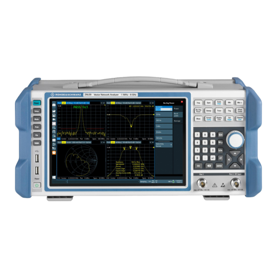
® Getting Started R&S ZNL/ZNLE Instrument Tour 4.1.6.1 Setting the User Interface Language The user interface to the R&S ZNL/ZNLE is available in several languages. Changing the user interface language 1. Press the [SETUP] key. 2. Press the "Language" softkey. 3. - Page 72 ® Getting Started R&S ZNL/ZNLE Instrument Tour Figure 4-1: Front panel view 1 = Power key 2 = USB (2.0) connectors 3 = System keys 4 = Touchscreen 5 = Function keys 6 = Keypad 7 = Navigation controls 8 = Port 1 9 = Port 2 / RF Input 50 Ω...
- Page 73 ® Getting Started R&S ZNL/ZNLE Instrument Tour Figure 4-2: Touchscreen elements 1 = Toolbar with standard application functions, e.g. print, save/open file etc. 2 = Tabs for individual channel setups 3 = Softtool panel (a.k.a. softkey bar) 4 = Window title bar with diagram-specific (trace) information 5 = Measurement results (diagram) area 6 = Channel list 7 = Diagram footer with diagram-specific information...
- Page 74 ® Getting Started R&S ZNL/ZNLE Instrument Tour For details on touchscreen gestures see Chapter 4.4.4, "Touchscreen Gestures", on page 80. 4.2.1.2 Power Key The [Power] key is located on the lower left corner of the front panel. It starts up and shuts down the instrument.
- Page 75 ® Getting Started R&S ZNL/ZNLE Instrument Tour 4.2.1.5 Function Keys Function keys provide access to the most common measurement settings and func- tions. A detailed description of the corresponding functions is provided in the User Manual. The labels indicated in italics (blue font color on the instrument) apply to the optional Spectrum mode only.
- Page 76 ® Getting Started R&S ZNL/ZNLE Instrument Tour Function key Assigned functions VNA mode SA mode (R&S ZNL only) [Offset Embed] Contains functions for deembedding/ Performs a peak search for active embedding the DUT from/into physical/ marker. If no marker is active, normal virtual (matching) networks placed marker 1 is activated and the peak between the calibrated reference plane...
- Page 77 ® Getting Started R&S ZNL/ZNLE Instrument Tour Type of key Description If an alphanumeric entry has already been started, this key deletes the character to the left of the cursor. (BACKSPACE) ● Concludes the entry of dimensionless entries. The new value is [ENTER] accepted.
- Page 78 ® Getting Started R&S ZNL/ZNLE Instrument Tour Arrow Left/Arrow Right Keys The <arrow left> or <arrow right> keys do the following: ● In an alphanumeric edit dialog box, move the cursor. ● In a list, scroll forward and backward through the list entries. ●...
-
Page 79: Rear Panel View
® Getting Started R&S ZNL/ZNLE Instrument Tour Risk of instrument damage Do not overload the input. For maximum allowed values, see the data sheet. A DC input voltage of 50 V must never be exceeded. 4.2.2 Rear Panel View This figure shows the rear panel view of the R&S ZNL/ZNLE. The individual elements are described in more detail in the subsequent sections. - Page 80 ® Getting Started R&S ZNL/ZNLE Instrument Tour Figure 4-4: Rear panel view R&S ZNLE 1 = AC Power Supply Connection and Main Power Switch 2 = GPIB ("IEC") interface 3 = Reference clock connectors 4 = Trigger input connector 5 = "DVI" connector for external display 6 = "LAN"...
- Page 81 ® Getting Started R&S ZNL/ZNLE Instrument Tour Risk of electric shock! If external power supply units for supplying safety extra-low DC voltage (SELV) to the instrument are used, the requirements for reinforced/double insulation in accordance with DIN/EN/IEC 61010 (UL 3111, CSA C22.2 No. 1010.1) or DIN/EN/IEC 60950 (UL 1950, CSA C22.2 No.
- Page 82 ® Getting Started R&S ZNL/ZNLE Instrument Tour Connector Reference signal Usage Ref. In 10 MHz To provide an external reference signal on the R&S ZNL/ZNLE. 10 dBm Ref. Out 10 MHz To provide the internal reference signal from the R&S ZNL/ZNLE to another device continuously. 10 dBm For the R&S ZNL this is also used to provide the optional OCXO reference signal to another device.
- Page 83 ® Getting Started R&S ZNL/ZNLE Instrument Tour 4.2.2.10 Aux. Port A 25-pole D-Sub connector used as an input and output for low-voltage TTL control signals. Can either be used as VNA User Port (max. 3.3 V) or SA Aux. Port (max. 5 V). At the FW GUI this can be set via [Setup] >...
-
Page 84: Trying Out The Instrument
® Getting Started R&S ZNL/ZNLE Trying Out the Instrument 4.2.2.12 Headphones Connector The Spectrum Mode provides demodulators for AM, FM and PM signals, which can be routed to the headphone connector. With headphones or an external loudspeaker con- nected to the 3.5 mm headphone socket the displayed signal can be identified acousti- cally. -
Page 85: Performing Measurements
® Getting Started R&S ZNL/ZNLE Trying Out the Instrument in the R&S ZNL/ZNLE User Manual. Basic instrument operation is described in Chap- ter 4.4, "Operating the Instrument", on page 74. Prerequisites ● The instrument is set up, connected to the mains system, and started up as descri- bed in Chapter 4.1, "Preparing for Use",... - Page 86 ® Getting Started R&S ZNL/ZNLE Trying Out the Instrument 4.3.1.1 Transmission S-Parameter Measurement In a transmission measurement, the analyzer transmits a stimulus signal to the input port of the device under test (DUT) and measures the transmitted wave at the DUT's output port.
- Page 87 ® Getting Started R&S ZNL/ZNLE Trying Out the Instrument Select [Trace] and use the control elements in the "Traces" softtool tab if you wish to create additional traces and diagrams. Selecting the Sweep Range and Other Parameters After a system preset the display shows a diagram with a dB magnitude scale, and the S-parameter S is selected as a measured quantity.
- Page 88 ® Getting Started R&S ZNL/ZNLE Trying Out the Instrument Calibrating the Instrument Calibration (system error correction) is the process of eliminating systematic, reprodu- cible errors from the measurement results. E.g., in the current test setup, the connect- ing cables between the analyzer ports and the DUT introduce an attenuation and a phase shift of the waves.
- Page 89 ® Getting Started R&S ZNL/ZNLE Trying Out the Instrument 4. Select "Next" to proceed to the next page of the "Calibration Setting" wizard. 5. Select the test port connector type and gender (here: N 50 Ω, female, correspond- ing to a male Through standard) and the calibration kit (here: R&S ZV-Z121), then click "Start".
- Page 90 ® Getting Started R&S ZNL/ZNLE Trying Out the Instrument The analyzer performs a calibration sweep for the measured quantity S . The magnitude and phase of the result is displayed in two diagrams, together with the expected typical result for a Through standard. The similarity of real and expected traces indicates that the Through standard has been properly connected.
- Page 91 ® Getting Started R&S ZNL/ZNLE Trying Out the Instrument 2. Open the [Mkr->] > "Peak" softtool tab and activate "Min" search. The marker jumps to the absolute minimum of the curve in the entire sweep range. The marker info field shows the coordinates of the new marker position. 3.
-
Page 92: Zooming Into The Display
® Getting Started R&S ZNL/ZNLE Trying Out the Instrument You can also use the basic transmission test setup, e.g. if you want to measure reflection and transmission parameters in parallel. ● The analyzer provides special calibration types for reflection measurements. Use the calibration wizard and select an appropriate type. -
Page 93: Saving Settings
® Getting Started R&S ZNL/ZNLE Trying Out the Instrument Figure 4-5: Defining the zoom area When you remove your finger, the zoom area is enlarged in a second (sub-)win- dow. Figure 4-6: Zoomed display around a peak 4.3.3 Saving Settings To restore the results of our measurements later, we will store the instrument settings to a file. - Page 94 ® Getting Started R&S ZNL/ZNLE Trying Out the Instrument Figure 4-7: Saving the instrument settings to a file 4. Tap the "Save" button. The file MyMultiViewSetup.dfl is stored in the default directory C:\Users\Public\Documents\Rohde-Schwarz\ZNL\user. To load stored instrument settings You can restore the settings to the instrument at any time using the settings file. 1.
-
Page 95: Printing And Saving Results
® Getting Started R&S ZNL/ZNLE Trying Out the Instrument 4.3.4 Printing and Saving Results Finally, after a successful measurement, we will document our results. First we will export the numeric trace data, then we will create a screenshot of the graphical display. To export the trace data 1. -
Page 96: Activating Additional Channel Setups
® Getting Started R&S ZNL/ZNLE Trying Out the Instrument 4.3.5 Activating Additional Channel Setups The R&S ZNL/ZNLE features multiple channel setups, i.e. you can define several mea- surement configurations in parallel and then switch between the channel setups auto- matically to perform the measurements sequentially. We will demonstrate this feature by activating additional channel setups for a different frequency range, a Spectrum measurement, and an I/Q analysis (note that the latter two measurements are only available if the optional Spectrum mode is installed). - Page 97 ® Getting Started R&S ZNL/ZNLE Trying Out the Instrument d) Drag the "Real/Imag (I/Q)" icon from the evaluation bar to the SmartGrid. Figure 4-9: Inserting a Real/Imag diagram for I/Q analysis e) Close the SmartGrid mode. The "IQ Analyzer" channel setup displays the real and imaginary signal parts in separate windows.
-
Page 98: Trying Out Spectrum Mode
® Getting Started R&S ZNL/ZNLE Trying Out the Instrument Figure 4-10: The "MultiView" tab 4.3.6 Trying Out Spectrum Mode If the "Spectrum Analysis" option R&S ZNL3|6-B1 is installed, you can use the instru- ment to perform spectrum measurements. The following chapters describe some basic tasks in Spectrum mode. - Page 99 ® Getting Started R&S ZNL/ZNLE Trying Out the Instrument 3. Press the [Setup] key. 4. Tap the "Service + Support" softkey. 5. Tap the "Calibration Signal" tab. 6. Tap the "Calibration Frequency RF" option. Leave the frequency at the default 50 MHz.
- Page 100 ® Getting Started R&S ZNL/ZNLE Trying Out the Instrument 3. Set the reference level to -25 dBm: a) In the configuration "Overview", tap the "Amplitude" button. b) In the "Value" field of the "Amplitude" dialog box, enter -25 dBm. The display of the calibration signal is now improved. The maximum at the center frequency (=calibration frequency) of 50 MHz becomes visible.
- Page 101 ® Getting Started R&S ZNL/ZNLE Trying Out the Instrument Drag the "Spectrogram" icon from the evaluation bar to the diagram area. The blue area indicates that the new diagram would replace the previous spectrum display. Since we do not want to replace the spectrum, drag the icon to the lower half of the display to add an additional window instead.
- Page 102 ® Getting Started R&S ZNL/ZNLE Trying Out the Instrument Figure 4-14: Spectrogram of the calibration signal 4.3.6.3 Setting and Moving a Marker Markers are useful to determine the position of particular effects in the trace. The most common use is to determine a peak, which is the default setting when you activate a marker.
- Page 103 ® Getting Started R&S ZNL/ZNLE Trying Out the Instrument 6. Now you can move the marker by tapping and dragging it to a different position. The current position is indicated by a dotted blue line. Notice how the position and value change in the marker area of the diagram.
-
Page 104: Performing Sequential Measurements
® Getting Started R&S ZNL/ZNLE Trying Out the Instrument 6. To obtain a more conclusive peak list that does not contain noise peaks, for exam- ple, define a threshold that is higher than the noise floor: a) Press the [MKR] key on the front panel. b) Tap the "Marker Config"... -
Page 105: Operating The Instrument
® Getting Started R&S ZNL/ZNLE Operating the Instrument Figure 4-16: "MultiView" tab with active Sequencer Figure 4-16, the "Spectrum 2" measurement is currently active (indicated by the "channel active" icon in the tab label). 3. Stop the Sequencer by tapping the "Sequencer" softkey again. 4.4 Operating the Instrument This chapter provides an overview on how to work with the R&S ZNL/ZNLE. -
Page 106: Understanding The Display Information (Vna Mode)
® Getting Started R&S ZNL/ZNLE Operating the Instrument ● Understanding the Display Information (VNA Mode)..........75 ● Accessing the Functionality..................76 ● Entering Data......................79 ● Touchscreen Gestures.................... 80 ● Getting Help......................83 ● Remote Control....................... 85 4.4.1 Understanding the Display Information (VNA Mode) The following figure shows a measurement diagram in VNA mode. -
Page 107: Accessing The Functionality
® Getting Started R&S ZNL/ZNLE Operating the Instrument 1 = Trace name 2 = Measured parameter 3 = Trace format 4 = Scale per division 5 = Reference value Diagram footer For each parameter diagram, a window is displayed with the following information in the footer: 1 = Channel 2 = Center frequency... - Page 108 ® Getting Started R&S ZNL/ZNLE Operating the Instrument 4.4.2.1 Toolbar Standard functions can be performed via the icons in the toolbar on the left side of the screen. You can hide the toolbar display, e.g. when using remote control, to enlarge the display area for the measurement results ("Setup"...
- Page 109 ® Getting Started R&S ZNL/ZNLE Operating the Instrument 4.4.2.3 Context Menus Several items in the diagram area have context menus (for example markers, traces or the channel bar). If you right-click on one of these items (or tap it for about 1 second), a menu is displayed which contains the same functions as the corresponding softkey.
-
Page 110: Entering Data
® Getting Started R&S ZNL/ZNLE Operating the Instrument When you press this key, the display switches between the following options: ● Keyboard displayed at the top of the screen ● Keyboard displayed at the bottom of the screen ● No keyboard displayed You can use the TAB key on the on-screen keyboard to move the focus from one field to another in dialog boxes. -
Page 111: Touchscreen Gestures
® Getting Started R&S ZNL/ZNLE Operating the Instrument 3. If the parameter does not require a unit, confirm the entered value by pressing the [ENTER] key or any of the unit keys. The editing line is highlighted to confirm the entry. Entering Alphanumeric Parameters If a field requires alphanumeric input, you can use the on-screen keyboard to enter numbers and (special) characters (see... - Page 112 ® Getting Started R&S ZNL/ZNLE Operating the Instrument Double-tapping Tap the screen twice, in quick succession. Double-tap the window title bar to maximize a window in the display, or to restore the original size. Double-tap a diagram to add a peak marker. The next available (delta) marker is set to the peak near the x-axis position you tapped.
- Page 113 ® Getting Started R&S ZNL/ZNLE Operating the Instrument Figure 4-21: Spreading Touch gestures in diagrams change measurement settings When you change the display using touch gestures, the corresponding measurement settings are adapted. This is different to selecting an area on the screen in zoom mode, where merely the resolution of the displayed trace points is changed temporarily (graphical zoom).
-
Page 114: Getting Help
® Getting Started R&S ZNL/ZNLE Operating the Instrument 4.4.5 Getting Help If any questions or problems concerning the R&S ZNL/ZNLE arise, an extensive online help system is provided on the instrument and can be consulted at any time. The help system is context-sensitive and provides information specifically for the current opera- tion or setting to be performed. - Page 115 ® Getting Started R&S ZNL/ZNLE Operating the Instrument The Help toolbar provides some buttons: ● To browse the topics in the order of the table of contents: Up arrow = previous topic, Down arrow = next topic ● To browse the topics visited before: Left arrow = back, Right arrow = forward ●...
-
Page 116: Remote Control
® Getting Started R&S ZNL/ZNLE Operating the Instrument 4.4.6 Remote Control In addition to working with the R&S ZNL/ZNLE interactively, located directly at the instrument, it is also possible to operate and control it from a remote PC. Various meth- ods for remote control are supported: ●... - Page 117 ® Getting Started R&S ZNL/ZNLE Operating the Instrument 4.4.6.3 Connecting a PC via the GPIB Interface You can connect a PC to the R&S ZNL/ZNLE via the GPIB interface to send remote commands to control and operate the instrument. You can configure the GPIB address and the ID response string.
-
Page 118: Operating Modes, Applications, Channel Setups, And Result Displays
® Operating Modes, Applications, Channel Setups, and Result Displays R&S ZNL/ZNLE 5 Operating Modes, Applications, Channel Setups, and Result Displays If the "Spectrum Analysis" hardware option R&S ZNL3/6-B1 is installed, the R&S ZNL is actually two instruments in one: a vector network analyzer (VNA) and a spectrum analyzer (SA). -
Page 119: Available Applications
® Operating Modes, Applications, Channel Setups, and Result Displays R&S ZNL/ZNLE Available Applications ● Available Applications..................... 88 ● R&S MultiView......................89 ● Defining Channel Setups..................90 ● Running a Sequence of Measurements..............92 5.1 Available Applications Access: [MODE] Without the spectrum analysis option, the R&S ZNL only provides the application. -
Page 120: R&S Multiview
® Operating Modes, Applications, Channel Setups, and Result Displays R&S ZNL/ZNLE R&S MultiView This option is not available for the R&S ZNLE. The "I/Q Analyzer" application is described in the R&S ZNL "I/Q Analyzer" User Man- ual. Remote command: INST:SEL IQ, see on page 508 INSTrument[:SELect] Analog Demod... -
Page 121: Defining Channel Setups
® Operating Modes, Applications, Channel Setups, and Result Displays R&S ZNL/ZNLE Defining Channel Setups 5.3 Defining Channel Setups Access: [MODE] For a R&S ZNL with spectrum analysis option R&S ZNL-B1, the startup/preset channel setup is determined by the Preset Mode. Factory default is "VNA". For the R&S ZNLE this is the only available application. - Page 122 ® Operating Modes, Applications, Channel Setups, and Result Displays R&S ZNL/ZNLE Defining Channel Setups Figure 5-1: Defining Channel Setups (R&S ZNL with R&S ZNL-B1) Switching between channel setups When you switch to a new channel setup, a set of parameters is passed on from the current channel setup to the new one: ●...
-
Page 123: Running A Sequence Of Measurements
® Operating Modes, Applications, Channel Setups, and Result Displays R&S ZNL/ZNLE Running a Sequence of Measurements Note: The channel setups are labeled with the application name. If that name already exists, a sequential number is added. You can change the name of the channel setup by double-tapping the name in the channel setup bar and entering a new name. - Page 124 ® Operating Modes, Applications, Channel Setups, and Result Displays R&S ZNL/ZNLE Running a Sequence of Measurements For each individual measurement, the sweep count is considered. Thus, each mea- surement may consist of several sweeps. The currently active measurement is indica- ted by a symbol in the tab label.
- Page 125 ® Operating Modes, Applications, Channel Setups, and Result Displays R&S ZNL/ZNLE Running a Sequence of Measurements Example: Sequencer procedure Assume the following active channel setup definition: Tab name Application Sweep mode Sweep count Cont. Sweep Spectrum Spectrum Cont. Sweep Spectrum 2 Spectrum Single Sweep IQ Analyzer...
-
Page 126: Sequencer Settings
® Operating Modes, Applications, Channel Setups, and Result Displays R&S ZNL/ZNLE Running a Sequence of Measurements RUN SINGLE/RUN CONT and Single Sweep/Sweep Continuous keys While the Sequencer is active, the [RUN SINGLE] and [RUN CONT] keys control the Sequencer, not individual sweeps. [RUN SINGLE] starts the Sequencer in single mode, while [RUN CONT] starts the Sequencer in continuous mode. - Page 127 ® Operating Modes, Applications, Channel Setups, and Result Displays R&S ZNL/ZNLE Running a Sequence of Measurements 1. Configure a channel setup for each measurement configuration as required, includ- ing the sweep mode. 2. In the toolbar, select the "Sequencer" icon. The "Sequencer"...
-
Page 128: Common Instrument Functions
® Common Instrument Functions R&S ZNL/ZNLE Toolbar Functions 6 Common Instrument Functions Some settings and functions are available throughout the instrument, regardless of the currently active application. These settings and functions are described here, and are not repeated for each application. ●... -
Page 129: Data Management
® Common Instrument Functions R&S ZNL/ZNLE Data Management Undo Reverts last operation, i.e. the status before the previous action is retrieved. The undo function is useful, for example, if you are performing a zero span measure- ment with several markers and a limit line defined and accidentally select a different measurement. -
Page 130: Restoring The Default Instrument Configuration (Preset)
® Common Instrument Functions R&S ZNL/ZNLE Data Management Chapter 6.2.2, "Storing and Recalling Instrument Settings and Measurement Data", on page 100. ● Hardcopy functions can be easily accessed via the [Print] system key. Chapter 6.2.3, "Creating Screenshots of Current Measurement Results and Settings", on page 109. -
Page 131: Storing And Recalling Instrument Settings And Measurement Data
® Common Instrument Functions R&S ZNL/ZNLE Data Management To restore the default configuration for a single channel setup The default measurement settings can also be reset for an individual channel setup only, rather than resetting the entire instrument. ► In the "Overview", select the "Preset Channel" button. The factory default settings are restored to the current channel setup. - Page 132 ® Common Instrument Functions R&S ZNL/ZNLE Data Management ● Quick Save/Quick Recall..................101 ● Configurable Storage and Recall................103 ● How to Save and Load Instrument Settings............107 6.2.2.1 Quick Save/Quick Recall The Quick Save and Quick Recall functions allow you to store instrument settings or channel setups very easily and quickly in one step.
- Page 133 ® Common Instrument Functions R&S ZNL/ZNLE Data Management QuickSave 1 / ... / QuickSave 10................102 Storage Type (Save only)....................102 Recall.......................... 102 QuickSave 1 / ... / QuickSave 10 Selects one of the save sets to store the current settings in or to be recalled. At the time of storage, the "QuickSave 1 / ...
- Page 134 ® Common Instrument Functions R&S ZNL/ZNLE Data Management Note: After you use the "Recall" function, the history of previous actions is deleted, i.e. any actions performed previously cannot be undone or redone using the [UNDO/ REDO] keys. Note: If a channel setup with the same name as the "Channel" to be restored (in a new "Channel") is already active, the name for the new channel setup is extended by a con- secutive number: In remote commands, you must append this number to the channel setup name, as...
- Page 135 ® Common Instrument Functions R&S ZNL/ZNLE Data Management Access: "Save"/ "Open" icon in the toolbar > "Save" / "Recall" Both dialog boxes are very similar and closely related. Selecting Storage Location - Drive/ Path/ Files............104 File name........................104 Comment........................104 File Type ........................105 Items:..........................
- Page 136 ® Common Instrument Functions R&S ZNL/ZNLE Data Management File Type Determines whether the global instrument settings with all "Channel"s are stored or recalled, or the current "Channel" settings only. Items: Defines which data and settings are stored or are recalled. Depending on the "File Type"...
- Page 137 ® Common Instrument Functions R&S ZNL/ZNLE Data Management Startup Recall......................106 Selecting Storage Location - Drive/ Path/ Files............106 File name........................106 Comment........................106 Startup Recall Activates or deactivates the startup recall function. If activated, the settings stored in the selected file are loaded each time the instrument is started or preset. If deactivated, the default settings are loaded.
- Page 138 ® Common Instrument Functions R&S ZNL/ZNLE Data Management Remote command: on page 515 MMEMory:COMMent 6.2.2.3 How to Save and Load Instrument Settings Instrument settings can be saved to a file and loaded again later, so that you can repeat the measurement with the same settings. Optionally, user-defined measurement settings can automatically be restored each time you start or preset the instrument.
- Page 139 ® Common Instrument Functions R&S ZNL/ZNLE Data Management 7. Select "Save". A file with the defined name and path and the extension .dfl is created. If you make any changes to the settings after storing the configuration file, remember to save the settings again. Otherwise those settings cannot be restored and will be overwritten by the stored values when the configuration file is recalled.
-
Page 140: Creating Screenshots Of Current Measurement Results And Settings
® Common Instrument Functions R&S ZNL/ZNLE Data Management 6.2.3 Creating Screenshots of Current Measurement Results and Set- tings To document the graphical results and the most important settings for the currently per- formed measurement, you can create a screenshot of the current display. Screenshots can either be printed or stored to a file. - Page 141 ® Common Instrument Functions R&S ZNL/ZNLE Data Management Print Screenshot......................111 Print Multiple Windows....................111 Comment........................111 Print Logo........................111 Print Page Count......................111 Print Dialog........................111 Print Date and Time.....................112 User Manual 1178.5966.02 ─ 06...
- Page 142 ® Common Instrument Functions R&S ZNL/ZNLE Data Management Print Screenshot Selects all measurement results displayed on the screen for the current channel setup (or "MultiView" ): diagrams, traces, markers, marker lists, limit lines, etc., including the channel bar and status bar, for printout on a single page. Displayed items belonging to the software user interface (e.g.
- Page 143 ® Common Instrument Functions R&S ZNL/ZNLE Data Management This setting is only available if Print Screenshot is selected. Print Date and Time Includes or removes the current date and time at the bottom of the printout. Remote command: on page 533 HCOPy:TDSTamp:STATe<device>...
- Page 144 ® Common Instrument Functions R&S ZNL/ZNLE Data Management Zoom In / Zoom Out....................113 Page........................113 Zoom 1:1........................113 Page Up / Page Down....................113 Print..........................113 Zoom In / Zoom Out Zooms into (enlarges) or zooms out of (decreases) the preview display. Note that the zoom functions affect only the preview, not the printout itself.
- Page 145 ® Common Instrument Functions R&S ZNL/ZNLE Data Management Destination........................114 Suppress File Name Dialog..................115 Printer Name....................... 115 Print to file........................115 Install Printer........................115 Destination Defines the medium to which the printout is output. User Manual 1178.5966.02 ─ 06...
- Page 146 ® Common Instrument Functions R&S ZNL/ZNLE Data Management "File" Stores the printout to a file in the selected format. The filename is queried at the time of storage, or a default name is used (see Sup- press File Name Dialog). Multiple windows can only be printed to a file in PDF format.
- Page 147 ® Common Instrument Functions R&S ZNL/ZNLE Data Management Page Setup Access: "Print" > "Print Config" > "Page Setup" tab Page settings are only available when printing on a printer or to a PDF file (see "Desti- nation" on page 114). Orientation........................116 Windows Per Page......................116...
- Page 148 ® Common Instrument Functions R&S ZNL/ZNLE Data Management Scaling Determines the scaling of the windows in the printout if Print Multiple Windows is active (see "Print Content Settings" on page 109). If more than one window is printed on one page (see Windows Per Page), each win- dow is printed in equal size.
- Page 149 ® Common Instrument Functions R&S ZNL/ZNLE Data Management The settings provided here are identical to those in the "Print Colors" section of the "Display" > "Theme + Color" dialog box. "Print Colors" on page 127. 6.2.3.2 How to Store or Print Screenshots of the Display The measurement results displayed on the screen can be printed or stored to a file very easily.
- Page 150 ® Common Instrument Functions R&S ZNL/ZNLE Data Management a) By default, "Optimized Colors" are used to improve the visibility of the colors. The background is always printed in white and the grid in black. For a printout that reflects exactly what you see on the screen, select "Screen Colors (Screenshot)".
-
Page 151: General Instrument Setup
® Common Instrument Functions R&S ZNL/ZNLE General Instrument Setup c) Check the "Print Preview" to make sure all relevant elements of the display are visible. 8. In the "Color" tab, define the colors to be used for the printout. a) By default, "Optimized Colors" are used to improve the visibility of the colors. The background is always printed in white and the grid in black. -
Page 152: Display Settings
® Common Instrument Functions R&S ZNL/ZNLE General Instrument Setup The R&S ZNL/ZNLE can use the internal reference source or an external reference source as the frequency standard for all internal oscillators. A 10 MHz crystal oscillator is used as the internal reference source. In the external reference setting, all internal oscillators of the R&S ZNL/ZNLE are synchronized to the external reference frequency. - Page 153 ® Common Instrument Functions R&S ZNL/ZNLE General Instrument Setup Deactivating and Activating the Touchscreen............. 122 Display Update Rate....................122 Set Date and Time ..................... 122 Date and Time Format ....................123 Background Lighting....................123 Deactivating and Activating the Touchscreen The touchscreen function can be deactivated, e.g. when the instrument is being used for demonstration purposes and tapping the screen must not provoke an action.
- Page 154 ® Common Instrument Functions R&S ZNL/ZNLE General Instrument Setup Date and Time Format Switches the time and date display on the screen between US and German (DE) for- mat. Remote command: on page 543 DISPlay[:WINDow]:TIME:FORMat Background Lighting Changes the brightness of the display in eight steps. Remote command: on page 542 DISPlay:BLIGhting...
- Page 155 ® Common Instrument Functions R&S ZNL/ZNLE General Instrument Setup Date and Time......................125 Front Panel........................125 Mini Front Panel......................125 Toolbar The toolbar provides access to frequently used functions via icons at the top of the screen. Some functions, such as zooming, finding help, printing screenshots or storing and loading files are not accessible at all without the toolbar.
- Page 156 ® Common Instrument Functions R&S ZNL/ZNLE General Instrument Setup Date and Time The date and time display can be switched off independently of the status bar. You can set the current date and time and configure the display format in the "General" tab of the "Display"...
- Page 157 ® Common Instrument Functions R&S ZNL/ZNLE General Instrument Setup Note: You can also activate the mini front panel using the key combination [ALT + m] (be aware of the keyboard language defined in the operating system!). That is useful when you are working from a remote PC and the front panel function is not active.
- Page 158 ® Common Instrument Functions R&S ZNL/ZNLE General Instrument Setup Theme......................... 127 Print Colors......................... 127 Showing Print Colors on Display.................127 Theme The theme defines the colors and style used to display softkeys and other screen objects. The default theme is "IndustrialDark". Remote command: on page 545 DISPlay:THEMe:SELect...
- Page 159 ® Common Instrument Functions R&S ZNL/ZNLE General Instrument Setup 6.3.2.2 External Monitor Settings Access: [Setup] > "Display" > "Configure Monitor" You can connect an external monitor (or projector) to the [DVI] or [display port] connec- tor on the instrument's rear panel (see the R&S ZNL/ZNLE getting started manual). Screen resolution and format The touchscreen of the R&S ZNL/ZNLE is calibrated for a 16:10 format.
- Page 160 ® Common Instrument Functions R&S ZNL/ZNLE General Instrument Setup ● Select a predefined set of colors for printing screenshots. ● Select "User Defined Colors" to configure the color set yourself. 5. Activate the "Show Print Colors on Display" option to see a preview of the print col- ors.
-
Page 161: Language Settings
® Common Instrument Functions R&S ZNL/ZNLE General Instrument Setup Icon Function Turn left Enter Turn right Mini front panel The mini front panel provides only the keys on the touchscreen, to operate the R&S ZNL/ZNLE via an external monitor or remote desktop. By default, the "Auto close"... -
Page 162: System Configuration Settings
® Common Instrument Functions R&S ZNL/ZNLE General Instrument Setup 6.3.4 System Configuration Settings Access: [Setup] > "System Configuration" ● Hardware Information....................131 ● Information on Versions and Options..............131 ● System Messages....................133 ● Firmware Updates....................134 ● General Configuration Settings................135 ● Additional Interfaces....................136 6.3.4.1... - Page 163 ® Common Instrument Functions R&S ZNL/ZNLE General Instrument Setup Expired option licenses If an option is about to expire, a message box is displayed to inform you. You can then use the "Install Option" function to enter a new license key. If an option has already expired, a message box appears for you to confirm.
-
Page 164: System Messages
® Common Instrument Functions R&S ZNL/ZNLE General Instrument Setup Install Option Opens an edit dialog box to enter the license key for the option that you want to install. Install Option by XML Opens a file selection dialog box to install an additional option to the R&S ZNL/ZNLE using an XML file. -
Page 165: Firmware Updates
® Common Instrument Functions R&S ZNL/ZNLE General Instrument Setup Remote command: on page 552 SYSTem:ERRor:LIST? 6.3.4.4 Firmware Updates Access: [Setup] > "System Configuration" > "Firmware Update" During instrument start, the installed hardware is checked against the current firmware version to ensure the hardware is supported. If not, an error message is displayed ( "Wrong Firmware Version"... -
Page 166: General Configuration Settings
® Common Instrument Functions R&S ZNL/ZNLE General Instrument Setup How to Update the Instrument Firmware 1. Download the update package from the Rohde&Schwarz website and store it on a memory stick, on the instrument, or on a server network drive that can be accessed by the instrument. -
Page 167: Additional Interfaces
® Common Instrument Functions R&S ZNL/ZNLE General Instrument Setup Remote command: on page 553 SYSTem:PRESet:COMPatible Out-of-range value behavior By default, if you enter a value that is outside the valid range in an input field for a set- ting, a warning is displayed and the value is not accepted. Alternatively, entries below the minimum value can automatically be set to the minimum possible entry, and entries above the maximum value set to the maximum possible entry. -
Page 168: Service Functions
® Common Instrument Functions R&S ZNL/ZNLE General Instrument Setup "VNA (User VNA channel setups can use the Aux. Port as VNA User Port (3.3 V). Port 3.3 V)" For details on the connector, see Chapter 11.1.1.1, "Aux. Port", on page 965. In this mode, SA channel setups cannot use any of the Additional Interfaces. - Page 169 ® Common Instrument Functions R&S ZNL/ZNLE General Instrument Setup Create R&S Support Information ................138 Save Device Footprint....................138 Create R&S Support Information Creates a *.zip file with important support information. The *.zip file contains the sys- tem configuration information ( "Device Footprint" ), the current eeprom data and a screenshot of the screen display.
- Page 170 ® Common Instrument Functions R&S ZNL/ZNLE General Instrument Setup 6.3.5.2 Self-test Settings and Results Access: [Setup] > "Service" > "Selftest" If the R&S ZNL/ZNLE fails you can perform a self-test of the instrument to identify any defective modules. Once the self-test is started, all modules are checked consecutively and the test result is displayed.
- Page 171 ® Common Instrument Functions R&S ZNL/ZNLE General Instrument Setup NONE .........................140 Calibration Frequency RF................... 140 └ Frequency..................... 140 NONE Uses the current RF signal at the input, i.e. no calibration signal (default). Remote command: on page 540 DIAGnostic:SERVice:INPut[:SELect] Calibration Frequency RF Uses the internal calibration signal as the RF input signal.
- Page 172 ® Common Instrument Functions R&S ZNL/ZNLE General Instrument Setup Service Function......................141 Send ...........................141 Clear History....................... 141 Password........................141 Clear Results.......................142 Save Results....................... 142 Result list........................142 Service Function Selects the service function by its numeric code or textual name. The selection list includes all functions previously selected (since the last "Clear His- tory"...
-
Page 173: Vna Setup
® Common Instrument Functions R&S ZNL/ZNLE General Instrument Setup Clear Results Clears the result display for all previously performed service functions. Remote command: on page 554 DIAGnostic:SERVice:SFUNction:RESults:DELete Save Results Opens a file selection dialog box to save the results of all previously performed service functions to a file. - Page 174 ® Common Instrument Functions R&S ZNL/ZNLE General Instrument Setup Auto Power Reduction for Cal Unit Sets the source power at all test ports to -10 dBm while an automatic calibration is active. Applying this source power to the ports of the calibration unit ensures best accuracy of the automatic calibration.
- Page 175 ® Common Instrument Functions R&S ZNL/ZNLE General Instrument Setup Sounds / Transparent Info Fields / Show Sweep Symbols The buttons switch the instrument messages, acoustic messages, transparent info fields for markers and trace statistics, and sweep symbols on or off. ●...
- Page 176 ® Common Instrument Functions R&S ZNL/ZNLE General Instrument Setup If active, the resistance R<i> is displayed and specified as conductance G<i> (=1/ R<i>). Remote command: SYSTem:DISPlay:CONDuctancesn/a Pressing Hardkey Reactivates Softkey Bar If the checkbox is selected (default), then pressing a function key displays the related softtool and keeps the softkey bar open.
- Page 177 ® Common Instrument Functions R&S ZNL/ZNLE General Instrument Setup Geometric Calculation of Bandfilter Center Defines how bandfilter searches calculate the center frequency of the passband or stopband (see "Bandfilter Search" on page 200). If "Geometric Calculation of Bandfilter Center" is checked, the geometric mean of the lower band edge and upper band edge frequencies is used, otherwise their arithmetic mean.
- Page 178 ® Common Instrument Functions R&S ZNL/ZNLE General Instrument Setup Positive Number Prefix ← Touchstone Export Options Positive numbers can either be prefixed by blanks, by plus signs or not at all. Remote command: MMEMory:STORe:TRACe:OPTion:PLUS Skip Separator Lines ← Touchstone Export Options If checked, the content parts are no longer separated by blank lines.
-
Page 179: Network And Remote Settings
® Common Instrument Functions R&S ZNL/ZNLE Network and Remote Settings ● "Reduce" is intended for measurements on sensitive DUTs. If enabled, at sweep end the output power of the driving port is reduced as if the channel base power was set to its minimum possible value. The configured settling delay is applied. ●... - Page 180 ® Common Instrument Functions R&S ZNL/ZNLE Network and Remote Settings Table 6-2: Remote control interfaces and protocols Interface Remarks Protocols, VISA address string ● Local Area HiSLIP High-Speed LAN Instrument Protocol (IVI-6.1) A LAN connector is located on the TCPIP::host address::hislip0[::INSTR] Network rear panel of the instrument.
- Page 181 ® Common Instrument Functions R&S ZNL/ZNLE Network and Remote Settings The R&S ZNL/ZNLE supports various LAN protocols such as LXI, RSIB, raw socket or the newer HiSLIP protocol. IP address Only the IP address or a valid DNS host name is required to set up the connection. The host address is part of the "VISA resource string"...
- Page 182 ® Common Instrument Functions R&S ZNL/ZNLE Network and Remote Settings VXI-11 Protocol The VXI-11 standard is based on the ONC RPC (Open Network Computing Remote Procedure Call) protocol which in turn relies on TCP/IP as the network/transport layer. The TCP/IP network protocol and the associated network services are preconfigured. TCP/IP ensures connection-oriented communication, where the order of the exchanged messages is adhered to and interrupted links are identified.
- Page 183 ® Common Instrument Functions R&S ZNL/ZNLE Network and Remote Settings the port configured for remote-control. All R&S ZNL/ZNLE use port number 5025 for this purpose. The port is configured for communication on a command-to-command basis and for remote control from a program. LXI Web Browser Interface LAN eXtensions for Instrumentation (LXI) is an instrumentation platform for measuring instruments and test systems that is based on standard Ethernet technology.
- Page 184 ® Common Instrument Functions R&S ZNL/ZNLE Network and Remote Settings The navigation pane of the browser interface contains the following elements: ● "LXI" – "Home" opens the instrument home page. The home page displays the device information required by the LXI standard, including the VISA resource string in read-only format.
- Page 185 ® Common Instrument Functions R&S ZNL/ZNLE Network and Remote Settings – "File Upload" uploads files to the instrument. (See Chapter 6.4.5.5, "How to Control the R&S ZNL/ZNLE via the Web Browser Interface", on page 176.) ● "License Manager" – "License Manager" allows you to install or uninstall license keys and to acti- vate, register or unregister licenses.
-
Page 186: Scpi (Standard Commands For Programmable Instruments)
® Common Instrument Functions R&S ZNL/ZNLE Network and Remote Settings Universal Commands Universal commands are encoded in the range 10 through 1F hex. They affect all instruments connected to the bus and do not require addressing. Command Effect on the instrument DCL (Device Clear) Aborts the processing of the commands just received and sets the com- mand processing software to a defined initial state. -
Page 187: Visa Libraries
® Common Instrument Functions R&S ZNL/ZNLE Network and Remote Settings Tables provide a fast overview of the bit assignment in the status registers. The tables are supplemented by a comprehensive description of the status registers. 6.4.3 VISA Libraries VISA is a standardized software interface library providing input and output functions to communicate with instruments. - Page 188 ® Common Instrument Functions R&S ZNL/ZNLE Network and Remote Settings Computer Name......................157 Address........................157 Subnet Mask....................... 158 DHCP.......................... 158 Network Configuration....................158 Computer Name Each instrument is delivered with an assigned computer name, but this name can be changed. The naming conventions of Windows apply. If too many characters and/or numbers are entered, an error message is displayed in the status line.
- Page 189 ® Common Instrument Functions R&S ZNL/ZNLE Network and Remote Settings Subnet Mask Defines the subnet mask. The TCP/IP protocol is preinstalled with the subnet mask 255.255.255.0. If the DHCP server is available ("DHCP On"), this setting is read-only. The subnet mask consists of four number blocks separated by dots. Each block con- tains 3 numbers in maximum (e.g.
- Page 190 ® Common Instrument Functions R&S ZNL/ZNLE Network and Remote Settings GPIB Address......................159 Identification String......................159 Reset to Factory String....................159 Remote Display Update....................159 GPIB Terminator......................159 Logging........................160 Display Remote Errors....................160 GPIB Address Defines the GPIB address. Values from 0 to 30 are allowed. The default address is 20. Remote command: on page 546 SYSTem:COMMunicate:GPIB[:SELF]:ADDRess...
- Page 191 ® Common Instrument Functions R&S ZNL/ZNLE Network and Remote Settings I/O Logging Activates or deactivates the SCPI error log function. All remote control commands received by the R&S ZNL/ZNLE are recorded in a log file. The files are named accord- ing to the following syntax: C:\ProgramData\Rohde-Schwarz\ZNL-FPL\ScpiLogging\ScpiLog.<no.>...
- Page 192 ® Common Instrument Functions R&S ZNL/ZNLE Network and Remote Settings Language........................161 Language Defines the system language used to control the instrument. Note: Emulating previous R&S signal and spectrum analyzers. This function is also used to emulate previous R&S signal and spectrum analyzers. As a rule, the R&S ZNL/ZNLE supports most commands from previous R&S signal and spectrum analyzers.
- Page 193 ® Common Instrument Functions R&S ZNL/ZNLE Network and Remote Settings Current LXI Configuration................... 162 Password......................162 LXI Manufacturer Description..................163 Reset........................163 Current LXI Configuration Displays the current LXI information from the R&S ZNL/ZNLE (read-only). "Current ver- Current LXI version sion" "LXI Extended Detected LXI features, such as HiSlip (see "HiSLIP Protocol"...
- Page 194 ® Common Instrument Functions R&S ZNL/ZNLE Network and Remote Settings Remote command: on page 549 SYSTem:LXI:PASSword LXI Manufacturer Description Instrument description of the R&S ZNL/ZNLE Remote command: on page 549 SYSTem:LXI:MDEScription LAN Reset Resets the LAN configuration to its default settings (LCI function). According to the LXI standard, an LCI must set the following parameters to a default state.
- Page 195 ® Common Instrument Functions R&S ZNL/ZNLE Network and Remote Settings The most recent error message during remote operation can be displayed on the screen, see "Display Remote Errors" on page 160. If the number of error messages exceeds the capacity of the error buffer, the oldest error message is removed before the newest one is inserted.
- Page 196 ® Common Instrument Functions R&S ZNL/ZNLE Network and Remote Settings 6.4.4.6 Returning to Manual Mode ("Local") When switched on, the instrument is always in the manual measurement mode and can be operated via the front panel. As soon as the instrument receives a remote com- mand, it is switched to the remote control mode.
-
Page 197: How To Set Up A Network And Remote Control
® Common Instrument Functions R&S ZNL/ZNLE Network and Remote Settings 6.4.5 How to Set Up a Network and Remote Control Risk of network failure Consult your network administrator before performing the following tasks: ● Connecting the instrument to the network ●... - Page 198 ® Common Instrument Functions R&S ZNL/ZNLE Network and Remote Settings Windows Firewall Settings A firewall protects an instrument by preventing unauthorized users from gaining access to it through a network. Rohde & Schwarz highly recommends the use of the firewall on your instrument.
- Page 199 ® Common Instrument Functions R&S ZNL/ZNLE Network and Remote Settings When a DHCP server is used, a new IP address may be assigned each time the PC is restarted. This address must first be determined on the PC itself. Thus, when using a DHCP server, it is recommended that you use the permanent computer name, which determines the address via the DNS server (see "Using a DNS server to determine the...
- Page 200 ® Common Instrument Functions R&S ZNL/ZNLE Network and Remote Settings If DHCP is "On", the IP address of the DHCP server is obtained automatically. The configuration is saved, and you are prompted to restart the instrument. You can skip the remaining steps. Note: When a DHCP server is used, a new IP address may be assigned each time the instrument is restarted.
- Page 201 ® Common Instrument Functions R&S ZNL/ZNLE Network and Remote Settings 7. Select the "Properties" button. 8. On the "General" tab, select "Use the following DNS server addresses" and enter your own DNS addresses. For more information refer to the Windows operating system Help. How to Change the Instrument Name In a LAN that uses a DNS server (Domain Name System server), each PC or instru- ment connected in the LAN can be accessed via an unambiguous computer name...
- Page 202 ® Common Instrument Functions R&S ZNL/ZNLE Network and Remote Settings The instrument home page displays the device information required by the LXI stan- dard including the VISA resource string in read-only format. ► Press the "Device Indicator" button on the "Instrument Home Page" to activate or deactivate the LXI status icon on the status bar of the R&S ZNL/ZNLE.
- Page 203 ® Common Instrument Functions R&S ZNL/ZNLE Network and Remote Settings ● "Ping Client" provides the ping utility to verify the connection between the instru- ment and other devices. IP Configuration The "LAN Configuration > IP configuration" web page displays all mandatory LAN parameters and allows their modification.
- Page 204 ® Common Instrument Functions R&S ZNL/ZNLE Network and Remote Settings 3. Select "Submit". How to Change the GPIB Instrument Address In order to operate the instrument via remote control, it must be addressed using the GPIB address. The remote control address is factory-set to 20, but it can be changed if it does not fit in the network environment.
- Page 205 ® Common Instrument Functions R&S ZNL/ZNLE Network and Remote Settings How to Create Users After the software for the network has been installed, the instrument issues an error message the next time it is switched on because there is no user named "instrument" (= default user ID for Windows automatic login) in the network.
- Page 206 ® Common Instrument Functions R&S ZNL/ZNLE Network and Remote Settings How to Activate or Deactivate the Automatic Login Mechanism Deactivating the automatic login mechanism When shipped, the instrument is already configured to automatically log on under Win- dows. To deactivate the automatic login mechanism, perform the following steps: 1.
- Page 207 ® Common Instrument Functions R&S ZNL/ZNLE Network and Remote Settings 6.4.5.5 How to Control the R&S ZNL/ZNLE via the Web Browser Interface Via the LXI browser interface to the R&S ZNL/ZNLE one or more users can control the instrument remotely from another PC without additional installation. Most instrument controls are available via the front panel simulation.
- Page 208 ® Common Instrument Functions R&S ZNL/ZNLE Network and Remote Settings The most commonly used folders on the instrument are displayed, for example those that contain user data, as well as the top-most My Computer folder, from which you can access all other folders on the instrument. 3.
- Page 209 ® Common Instrument Functions R&S ZNL/ZNLE Network and Remote Settings 6. Set "Startup type" to "Disabled". 7. Select "Stop". 8. Select "Apply". The next time a user enters the IP address of the instrument in a web browser, an error message is displayed: Failed to connect to server (code.
- Page 210 ® Common Instrument Functions R&S ZNL/ZNLE Network and Remote Settings Note: To avoid problems, use a fixed IP address. When a DHCP server is used, a new IP address is assigned each time the instru- ment is restarted. This address must first be determined on the instrument itself. Thus, using a DHCP server is not suitable for remote operation of the R&S ZNL/ ZNLE via Remote Desktop.
- Page 211 ® Common Instrument Functions R&S ZNL/ZNLE Network and Remote Settings How to Configure the Controller Remote Desktop Client With Windows, Remote Desktop Client is part of the operating system and can be accessed via "Start > Programs > Accessories > Remote Desktop Connection". For other versions of Windows, Microsoft offers the Remote Desktop Client as an add- Select the "Windows"...
- Page 212 ® Common Instrument Functions R&S ZNL/ZNLE Network and Remote Settings 7. Open the "Local Resources" tab for enabling printers, local drives and serial inter- faces. 8. If you will need to access drives of the controller from the R&S ZNL/ZNLE (e.g. in order to store settings or to copy files from the controller to the R&S ZNL/ZNLE), select "More", then enable the "Drives"...
- Page 213 ® Common Instrument Functions R&S ZNL/ZNLE Network and Remote Settings ● If activated, a bar showing the network address of the R&S ZNL/ZNLE will appear at the top edge of the screen. You can use this bar to reduce, minimize or close the window.
- Page 214 ® Common Instrument Functions R&S ZNL/ZNLE Network and Remote Settings The firmware restarts and then automatically opens the "Soft Front Panel", i.e. the user interface on which all front panel controls and the rotary knob are mapped to buttons. For more information see Chapter 6.3.2.4, "How to Work with the Soft Front Pan- els", on page 129.
- Page 215 ® Common Instrument Functions R&S ZNL/ZNLE Network and Remote Settings Restoring the connection to the R&S ZNL/ZNLE Follow the instructions above for setting up a connection to the R&S ZNL/ZNLE. If the connection is terminated and then restored, the R&S ZNL/ZNLE remains in the same state.
- Page 216 ® Common Instrument Functions R&S ZNL/ZNLE Network and Remote Settings 5. To enable the keys of the R&S ZNL/ZNLE again, switch the instrument to local mode (GTL - Go to Local), i.e. deactivate the REN line of the remote control inter- face.
-
Page 217: Vna Concepts And Features
® VNA Concepts and Features R&S ZNL/ZNLE Basic Concepts 7 VNA Concepts and Features The following chapter provides an overview of the instrument's VNA capabilities and their use. It contains a description of the basic concepts that the analyzer uses to organize, process and display measurement data. -
Page 218: Channel Setups
® VNA Concepts and Features R&S ZNL/ZNLE Basic Concepts 7.1.2 Channel Setups A channel setup comprises a set of diagrams together with the underlying system, channel, trace and display settings. The R&S ZNL/ZNLE can handle multiple channel setups in parallel, each of them displayed in a separate tab. Either the active channel setup or the set of all open channel setups can be saved to a settings file (*.dfl) and recalled at a later point in time or at another instrument. - Page 219 ® VNA Concepts and Features R&S ZNL/ZNLE Basic Concepts 7.1.3.1 Trace Settings The trace settings specify the mathematical operations used to obtain traces from the measured or stored data. They can be divided into several main groups: ● Selection of the measured quantity (S-parameters, wave quantities, ratios, impe- dances,...) ●...
-
Page 220: Sweep Control
® VNA Concepts and Features R&S ZNL/ZNLE Basic Concepts The channel settings can be accessed via the function keys [Freq], [Span], [Bw Avg Power], [Sweep], [Cal], [Channel], [Trigger] and [Offset Embed]. 7.1.3.3 Active and Inactive Traces and Channels A window can display several diagrams simultaneously, each with a variable number of traces. - Page 221 ® VNA Concepts and Features R&S ZNL/ZNLE Basic Concepts After changing the channel settings or selecting another measured quantity, the ana- lyzer needs some time to initialize the new sweep. This preparation period increases with the number of points and the number of partial measurements involved. It indica- ted in the status bar: All analyzer settings can still be changed during sweep initialization.
- Page 222 ® VNA Concepts and Features R&S ZNL/ZNLE Basic Concepts Use the "Alternated" mode to increase the accuracy of measurements on DUTs with long level settling times (e.g. quartzes, SAW filters). To measure DUTs with short set- tling times and obtain a trace from the beginning of the sweep, use "Chopped" mode. In "Auto"...
-
Page 223: Vna Screen Elements
® VNA Concepts and Features R&S ZNL/ZNLE VNA Screen Elements The ranges of numerical values must be compatible with the instrument model. The conditions for the stimulus range depend on the sweep type: ● "Lin Freq" / "Log Freq" / "Segmented" The supported frequency range depends on the instrument type;... - Page 224 ® VNA Concepts and Features R&S ZNL/ZNLE VNA Screen Elements ● An indication of the basic channel and trace settings ● Context menus providing settings which are related to a particular display element The examples in this section have been taken from Cartesian diagrams. All other dia- gram types provide the same display elements.
- Page 225 ® VNA Concepts and Features R&S ZNL/ZNLE VNA Screen Elements The trace can be complemented by the following display elements, plotted with the same color: ● Reference value (for all traces): The reference value is indicated with a triangle at the right edge of the diagram and a dashed, horizontal line.
- Page 226 ® VNA Concepts and Features R&S ZNL/ZNLE VNA Screen Elements name indicates a memory trace (default naming). To change the trace names, open the "Trace Manager" from any trace name segment's context menu. ● The measured quantity (e.g. an S-parameter or a ratio) appears on a colored background.
- Page 227 ® VNA Concepts and Features R&S ZNL/ZNLE VNA Screen Elements 7.2.1.3 Markers Markers are tools for numerical readout of measured data and for selecting points on the trace, or, in general, in the diagram area. A marker is displayed with a symbol (e.g. a triangle, a crossbar or a line) on the trace, which can be a data trace or a memory trace.
- Page 228 ® VNA Concepts and Features R&S ZNL/ZNLE VNA Screen Elements If the marker position is adjusted using the roll key, the mouse or the cursor keys, it always remains within the sweep range. If set explicitly by entering a numeric value, the marker position can be outside the sweep range.
- Page 229 ® VNA Concepts and Features R&S ZNL/ZNLE VNA Screen Elements Info Table If you wish to reserve the full diagram space for traces, you can drag & drop the marker info field to the info table. The info table is hidden by default. To display it, open the "Display Lines" softtool (hardkey [Display Lines]), activate its "Config"...
- Page 230 ® VNA Concepts and Features R&S ZNL/ZNLE VNA Screen Elements Marker Format Description Formula Lin Mag Phase Magnitude of z (unconverted) and phase in two |z| arctan ( Im(z) / Re(z) ) lines Real Imag Real and imaginary part of z in two lines R + j X Unnormalized resistance, reactance, and L or C in three lines (Smith diagram)
- Page 231 ® VNA Concepts and Features R&S ZNL/ZNLE VNA Screen Elements ● Trace points with a specific response value (target search). ● Trace segments with a shape that is characteristic for bandpass or bandstop filters (bandfilter search); see "Bandfilter Search" on page 200. When the search is activated, the active marker is moved to the (next) point that meets the search criteria.
- Page 232 ® VNA Concepts and Features R&S ZNL/ZNLE VNA Screen Elements ● "Lower Edge" is the closest frequency below the maximum (or minimum), where the trace value is equal to the maximum (minimum) value minus (plus) n dB. ● "Upper Edge" is the closest frequency above the maximum (or minimum), where the trace value is equal to the maximum (minimum) value minus (plus) n dB.
- Page 233 ® VNA Concepts and Features R&S ZNL/ZNLE VNA Screen Elements ● The color legend shows the display color of all traces assigned to the channel. The colors are different, so the number of colors is equal to the numbers of traces assigned to the channel.
-
Page 234: Dialogs
® VNA Concepts and Features R&S ZNL/ZNLE VNA Screen Elements The functions of the context menu can also be called from the related softtool panels. Use whatever method is most convenient. 7.2.2 Dialogs Dialogs provide groups of related settings and allow to make selections and enter data in an organized way. - Page 235 ® VNA Concepts and Features R&S ZNL/ZNLE VNA Screen Elements In most dialogs, however, it is possible to cancel an erroneous input before it takes effect. The settings in such dialogs must be confirmed explicitly. The two types of dialogs are easy to distinguish: ●...
-
Page 236: Trace Formats
® VNA Concepts and Features R&S ZNL/ZNLE VNA Screen Elements ● "Windows Explorer" opens the selected directory in the Windows Explorer. ● "File name" specifies a filename to save the current data. The analyzer adds the extension in the "Files of type" field. ●... - Page 237 ® VNA Concepts and Features R&S ZNL/ZNLE VNA Screen Elements The VNA firmware allows arbitrary combinations of trace formats and measured quan- tities. However, to extract useful information from the measured data, it is important to select a trace format which is appropriate for the analysis of a particular measured quantity;...
- Page 238 ® VNA Concepts and Features R&S ZNL/ZNLE VNA Screen Elements Figure 7-1: S11 trace in dB Mag format: sweep type Lin Freq (top) and Log Freq (bottom) Conversion of Complex to Real Quantities Among the measured quantities the R&S ZNL/ZNLE supports, only "Stability" factors and "Power Sensor"...
- Page 239 ® VNA Concepts and Features R&S ZNL/ZNLE VNA Screen Elements An extended range of formats and conversion formulas is available for markers. To convert any point on a trace, create a marker and select the appropriate marker format. Marker and trace formats can be selected independently. 7.2.3.2 Complex Trace Formats Complex trace formats assign a complex response to the stimulus value (frequency,...
- Page 240 ® VNA Concepts and Features R&S ZNL/ZNLE VNA Screen Elements Example: Reflection coefficients in polar diagrams If the measured quantity is a complex reflection coefficient (S etc.), then the cen- ter of the polar diagram corresponds to a perfect load Z at the input test port of the DUT (no reflection, matched input).
- Page 241 ® VNA Concepts and Features R&S ZNL/ZNLE VNA Screen Elements Smith chart construction In a Smith chart, the impedance plane is reshaped so that the area with positive resist- ance is mapped into a unit circle. The basic properties of the Smith chart follow from this construction: ●...
- Page 242 ® VNA Concepts and Features R&S ZNL/ZNLE VNA Screen Elements According to the two equations above, the graphical representation in a Smith chart has the following properties: ● Real reflection coefficients are mapped to real impedances (resistances). ● The center of the Γ plane (Γ = 0) is mapped to the reference impedance Z whereas the circle with |Γ| = 1 is mapped to the imaginary axis of the Z plane.
- Page 243 ® VNA Concepts and Features R&S ZNL/ZNLE VNA Screen Elements Inverted Smith chart construction The inverted Smith chart is point-symmetric to the Smith chart: The basic properties of the inverted Smith chart follow from this construction: ● The central horizontal axis corresponds to zero susceptance (real admittance). The center of the diagram represents Y/Y = 1, where Y is the reference admittance of...
- Page 244 ® VNA Concepts and Features R&S ZNL/ZNLE VNA Screen Elements From this equation, it is easy to relate the real and imaginary components of the com- plex admittance to the real and imaginary parts of Γ: ...
-
Page 245: Measurement Results
® VNA Concepts and Features R&S ZNL/ZNLE Measurement Results ● For complex "Impedances", "Admittances", "Z-parameters", and "Y-parameters" generally a Cartesian format or the polar format is suitable. ● For the real valued Stability Factors, one of the Cartesian formats "Lin Mag" or "Real"... - Page 246 ® VNA Concepts and Features R&S ZNL/ZNLE Measurement Results The figure above is sufficient for the definition of S-parameters but does not necessa- rily show the complete signal flow. In fact, if the source and load ports are not ideally matched, part of the transmitted waves are reflected off the receiver ports.
-
Page 247: Impedance Parameters
® VNA Concepts and Features R&S ZNL/ZNLE Measurement Results Table 7-3: Squared S-parameters Available incident power (= the power provided by a generator with a source impedance equal to the reference impedance Z ) at DUT port i=1,2 Reflected power at DUT port i=1,2 Reflection loss at DUT port i=1,2 10 log|S = 20 log|S... - Page 248 ® VNA Concepts and Features R&S ZNL/ZNLE Measurement Results The transmission parameters are calculated according to: The converted admittances are defined as the inverse of the impedances. Examples: ● is the input impedance of a 2-port DUT that is terminated at its output with the reference impedance Z (matched-circuit impedance measured in a forward reflec-...
-
Page 249: Admittance Parameters
® VNA Concepts and Features R&S ZNL/ZNLE Measurement Results This means that Z-parameters can be used as an alternative to S-parameters (or Y- parameters) to characterize a linear n-port network completely. 2-Port Z-Parameters In analogy to S-parameters, Z-parameters are expressed as Z , where i denotes the measured and j the stimulated port. - Page 250 ® VNA Concepts and Features R&S ZNL/ZNLE Measurement Results 7.3.3.1 Converted Admittances The converted admittance parameters describe the input admittances of a DUT with fully matched outputs. The converted admittances are the inverse of the converted impedances. The analyzer converts a single measured S-parameter to determine the corresponding converted admittance.
-
Page 251: Wave Quantities And Ratios
® VNA Concepts and Features R&S ZNL/ZNLE Measurement Results 2-Port Y-Parameters In analogy to S-parameters, Y-parameters are expressed as Y , where <out> <out>< in> and <in> denote the output and input port numbers of the DUT. In analogy to Z-param- eters, the Y-parameters for a two-port are based on a circuit model that can be expressed with two linear equations: ... - Page 252 ® VNA Concepts and Features R&S ZNL/ZNLE Measurement Results Examples for using wave quantities The wave quantities provide the power at the different receive ports of the analyzer. This is different from an S-parameter measurement, where the absolute power of a lin- ear device is canceled.
-
Page 253: Unbalance-Balance Conversion
® VNA Concepts and Features R&S ZNL/ZNLE Measurement Results ● "b Src Port 1" is the ratio of the outgoing wave at DUT port 1 and the incident wave at DUT port 1 (i.e. DUT port 1 ist stimulated). This corresponds to the forward reflection coefficient S 7.3.5 Unbalance-Balance Conversion Unbalance-balance conversion is the simulation of one or more unbalance-balance... - Page 254 ® VNA Concepts and Features R&S ZNL/ZNLE Measurement Results It is possible to assign arbitrary, independent reference impedance values to the differ- ential and common mode of the single balanced port. Example: Balanced port: Differential mode Log. Bal. port port Common mode The "Balanced Ports"...
-
Page 255: Reference Impedances
® VNA Concepts and Features R&S ZNL/ZNLE Measurement Results ● is the mixed mode forward transmission coefficient, defined as the <mout><min>21 ratio of the wave quantities b (mode mout) to a (mode min) (forward measure- ment with matched output and a = 0). - Page 256 ® VNA Concepts and Features R&S ZNL/ZNLE Measurement Results The default values for the balanced port reference impedances are derived from the default reference impedance of the physical analyzer ports (Z = 50 Ω): ● The default value for the differential mode is Z = 100 Ω...
-
Page 257: Stability Factors
® VNA Concepts and Features R&S ZNL/ZNLE Measurement Results In the model of Kurokawa ("Power Waves and the Scattering Matrix"), the wave quantities a and b are transformed as follows: ... -
Page 258: Delay, Aperture, Electrical Length
® VNA Concepts and Features R&S ZNL/ZNLE Measurement Results stability. This means that μ and μ provide direct insight into the degree of stability or potential instability of linear circuits. References: Marion Lee Edwards and Jeffrey H. Sinsky, "A New Criterion for Linear 2- Port Stability Using a Single Geometrically Derived Parameter", IEEE Trans. -
Page 259: Operations On Traces
® VNA Concepts and Features R&S ZNL/ZNLE Operations on Traces 7.4 Operations on Traces The R&S ZNL/ZNLE can perform more complex operations on the measured traces. Some of the operations, e.g. the time domain transform, require additional software options; see Chapter 7.7, "Optional Extensions and Accessories", on page 272. - Page 260 ® VNA Concepts and Features R&S ZNL/ZNLE Operations on Traces ● Gaps between segments are allowed and equivalent to switching off an intermedi- ate limit line segment. ● Limit lines can be partially or entirely outside the sweep range, however, the limits are only checked at the measurement points.
- Page 261 ® VNA Concepts and Features R&S ZNL/ZNLE Operations on Traces Exception: In a segmented frequency sweep with point-based x-axis, gaps between the segments are minimized. To facilitate the interpretation, the R&S ZNL/ZNLE dis- plays only the limit line segments which provide the limit check criterion (the "tighter" limit line at each point).
- Page 262 ® VNA Concepts and Features R&S ZNL/ZNLE Operations on Traces The limit line rules for logarithmic sweeps and segmented frequency sweeps with point-based x-axis also apply to ripple limit lines (see Chapter 7.4.1.1, "Rules for Limit Line Definition", on page 228). 7.4.1.3 Circle Limits A circle limit is a special type of upper limit line which is defined by its center coordi-...
- Page 263 ® VNA Concepts and Features R&S ZNL/ZNLE Operations on Traces ● With a circle limit line centered on the left border of an inverted Smith diagram (Y = infinity), you can check whether the imaginary part of the admittance (Im(Y), sus- ceptance) falls below a limit.
- Page 264 ® VNA Concepts and Features R&S ZNL/ZNLE Operations on Traces 7.4.1.4 File Format for Limit Lines The analyzer uses a simple ASCII format to export limit line data. By default, the limit line file has the extension *.limit and is stored in the directory shown in the "Save Limit Line"...
-
Page 265: Trace Files
® VNA Concepts and Features R&S ZNL/ZNLE Operations on Traces Compatibility with other instruments The VNAs of the R&S ZNx and R&S ZVx families use the same file format. Limit line files can be interchanged without restriction. 7.4.1.5 File Format for Ripple Limits The analyzer uses a simple ASCII format to export ripple limits. - Page 266 ® VNA Concepts and Features R&S ZNL/ZNLE Operations on Traces When exporting traces to a file, it is recommended to set the analyzer to single sweep mode ([Sweep] > ""Sweep Control"" > "All Channels on Hold"). This ensures that a complete sweep is exported.
- Page 267 ® VNA Concepts and Features R&S ZNL/ZNLE Operations on Traces can be replaced by an any S-parameter, so the *.s1p format is suitable for export- ing an arbitrary data trace representing an S-parameter. 2-port files (*.s2p) ! freq[Hz] re:S11 im:S11 re:S21 im:S21 re:S12...
- Page 268 ® VNA Concepts and Features R&S ZNL/ZNLE Operations on Traces If the reference impedances are identical and real this common resistance value is used as reference resistance of the Touchstone option line. Otherwise the value 50 Ω is used. ● Common Target Impedance For multi-port S-parameters, the reference resistance of the Touchstone option line is taken as common target impedance and the data is renormalized to the common...
- Page 269 ® VNA Concepts and Features R&S ZNL/ZNLE Operations on Traces or dB Mag-Phase, respectively. The data format for export files can be selected in the Export Data dialog. ● <imTrace1> second response value of first trace: im<Trace_Name> for output for- mat Re/Im, ang<Trace_Name>...
-
Page 270: Calibration
® VNA Concepts and Features R&S ZNL/ZNLE Calibration 7.5 Calibration Calibration or system error correction is the process of eliminating systematic, reprodu- cible errors from the measurement results (S-parameters and derived quantities). The process involves the following stages: 1. A set of calibration standards is selected and measured over the required sweep range. -
Page 271: Calibration Types
® VNA Concepts and Features R&S ZNL/ZNLE Calibration Cal Off label A label "Cal Off" appears in the trace line if the system error correction no longer applies to the trace: This can happen for one of the following reasons: ●... - Page 272 ® VNA Concepts and Features R&S ZNL/ZNLE Calibration Calibration Type Standards Parameters Error Terms General Accuracy Application One Path Two Ports Open, Short, for fixed source Reflection tracking, Medium to high Unidirectional trans- mission measure- Match (at source port j and target Source match, ments in any direc- port),...
- Page 273 ® VNA Concepts and Features R&S ZNL/ZNLE Calibration standard allows you to eliminate errors due to the directivity of the internal couplers, which improves the accuracy of reflection measurements on well-matched DUTs (high return loss). For reflection measurements on DUTs with low return loss, accuracy may be degraded compared to a simple reflection normalization.
- Page 274 ® VNA Concepts and Features R&S ZNL/ZNLE Calibration Match – Through) calibration. The four standards are used to derive 6 error terms for each signal direction: ● In addition to the source match and reflection tracking error terms provided by the one-path two-port calibration, TOSM also provides the load match.
-
Page 275: Calibration Standards And Calibration Kits
® VNA Concepts and Features R&S ZNL/ZNLE Calibration If isolation is measured, the corrected transmission coefficient of the DUT is calculated (Transmission coefficient DUT – Isolation) / (Transmission coefficient Through – Isola- tion) There is no dedicated physical standard for isolation measurement; it is recommended to terminate the test ports suitably (e.g. - Page 276 ® VNA Concepts and Features R&S ZNL/ZNLE Calibration Standard Type Characteristics Ideal Standard Offset Model Load Model Sliding match One-port standard consisting of an air line with a – – – movable, low-reflection load element (sliding load) ∞ Ω ☑ ☑...
- Page 277 ® VNA Concepts and Features R&S ZNL/ZNLE Calibration often the wave actually propagates through the line, whereas the offset loss is pro- portional to the attenuation of the line. To determine an offset loss value experimentally, measure the delay in seconds and the loss in dB at 1 GHz and use the formula above.
- Page 278 ® VNA Concepts and Features R&S ZNL/ZNLE Calibration The analyzer uses three types of parameters to describe the calibration standards. The parameter type is the same for all standards in a kit and therefore appended to the kit name: ● Universal parameters (no suffix) describe calibration kit models with highly stand- ardized components so that the parameters are valid for all calibration kits of the model.
- Page 279 ® VNA Concepts and Features R&S ZNL/ZNLE Calibration ● Loss: 0 dB / sqrt(GHz) or (0 GΩ / s) in Agilent mode ● All inductance and capacitance parameters are set to zero. 7.5.2.3 Sliding Match Standards The Sliding Match is a one-port standard consisting of an air line with a movable, low- reflection load element (sliding load).
- Page 280 ® VNA Concepts and Features R&S ZNL/ZNLE Calibration 7.5.2.4 Cal Kit Files Calibration kit files can be used to store the parameters of a particular calibration kit, to reload the data and to exchange calibration kits from one network analyzer to another. Cal kit file contents Cal kit files are independent of the current channel setup and contain the following information:...
-
Page 281: Calibration Pool
® VNA Concepts and Features R&S ZNL/ZNLE Calibration *.prn cal kit files: PNA Cal Kit Editor The network analyzer can import and process cal kit files created with the PNA Cal Kit Editor. The files use the extension *.prn; the data format is identical to the *.csv format. -
Page 282: Automatic Calibration
® VNA Concepts and Features R&S ZNL/ZNLE Calibration 7.5.5 Automatic Calibration A calibration unit is an integrated solution for automatic system error correction of vec- tor network analyzers. Rohde & Schwarz offers a wide range of calibration units for dif- ferent frequency ranges and connector types. - Page 283 ® VNA Concepts and Features R&S ZNL/ZNLE Calibration Calibration unit Frequency range Connector type No. of ports Order No. R&S ZN-Z151 100 kHz to 8.5 GHz N (f) 1317.9134.72 R&S ZN-Z151 100 kHz to 8.5 GHz SMA (f) 1317.9134.32 R&S ZN-Z152 100 kHz to 8.5 GHz SMA (f) 1319.6003.36...
- Page 284 ® VNA Concepts and Features R&S ZNL/ZNLE Calibration Safety instructions Please observe the safety instructions in the "Technical Information" provided with the calibration unit to avoid any damage to the unit and the network analyzer. Safety-rela- ted aspects of the connection and operation of the units are also reported in the follow- ing sections.
- Page 285 ® VNA Concepts and Features R&S ZNL/ZNLE Calibration Safety aspects ● The calibration unit is intended for direct connection to R&S ZNL/ZNLE network analyzers following the procedure described above. You can also connect the unit before switching on the analyzer. Do not connect the unit to other USB hosts, e.g. a PC, or insert any USB hubs between the analyzer and the unit, as this may dam- agethe unit or the host.
- Page 286 ® VNA Concepts and Features R&S ZNL/ZNLE Calibration Maximum RF input power The maximum RF input power of the calibration unit is beyond the RF output power range of the analyzer, so there is no risk of damage if the device is directly connected to the test ports.
-
Page 287: Parallel Calibration Of Multiple Channels
® VNA Concepts and Features R&S ZNL/ZNLE Offset Parameters and Embedding Dependency between calibration types and characterization data A cal unit characterization provides full one-port (OSM) data at the selected ports plus two-port (Through) data between any pair of selected ports. The measurement of Through data is optional, however, it is required for some calibration types. -
Page 288: Offset Parameters
® VNA Concepts and Features R&S ZNL/ZNLE Offset Parameters and Embedding 7.6.1 Offset Parameters Offset parameters compensate for the known length and loss of a (non-dispersive and perfectly matched) transmission line between the calibrated reference plane and the DUT. The analyzer can also auto-determine length and loss parameters, assuming that the actual values should minimize the group delay and loss across the sweep range. - Page 289 ® VNA Concepts and Features R&S ZNL/ZNLE Offset Parameters and Embedding For a lossless transmission line, Loss = Loss(f ) = 0 dB. In practice, the frequency- dependent loss often represents the dominant contribution so that Loss can be set to zero.
- Page 290 ® VNA Concepts and Features R&S ZNL/ZNLE Offset Parameters and Embedding Preconditions for Auto Length, effect on measured quantities and exceptions "Auto Length" is enabled if the measured quantity contains the necessary phase infor- mation as a function of frequency, and if the interpretation of the results is unambigu- ous: ●...
- Page 291 ® VNA Concepts and Features R&S ZNL/ZNLE Offset Parameters and Embedding ted admittances or impedances are calculated from the corresponding "Auto Length and Loss" corrected S-parameters. Y-parameters, Z-parameters and stability factors are not derived from a single S-parameter, therefore "Auto Length and Loss" is dis- abled.
- Page 292 ® VNA Concepts and Features R&S ZNL/ZNLE Offset Parameters and Embedding ● "Open and Short" causes the analyzer to calculate the correction data from two subsequent sweeps. The results are averaged to compensate for errors due to non-ideal terminations. Auto Length and Loss vs. Direct Compensation "Auto Length and Loss"...
-
Page 293: Embedding And Deembedding
® VNA Concepts and Features R&S ZNL/ZNLE Offset Parameters and Embedding The offset parameters are also suited for length and delay measurements; see Chap- ter 7.6.1.3, "Auto Length", on page 258. In contrast to the embedding/deembedding functions (see Chapter 7.6.2, "Embedding and Deembedding", on page 262) the parameters cannot compensate for a possible mismatch in the test setup. - Page 294 ® VNA Concepts and Features R&S ZNL/ZNLE Offset Parameters and Embedding ● A combination of four-port and two-port networks can be applied to any pair of sin- gle-ended ports. Moreover it is possible to combine several port pairs in an arbi- trary order (port pair de-/embedding).
- Page 295 ® VNA Concepts and Features R&S ZNL/ZNLE Offset Parameters and Embedding 7.6.2.3 Circuit Models for 2-Port Networks The lumped element 2-port transformation networks for (de-)embedding consist of the following two basic circuit blocks: ● a capacitor connected in parallel with a resistor ●...
- Page 296 ® VNA Concepts and Features R&S ZNL/ZNLE Offset Parameters and Embedding The following networks are composed of a shunt C or L (as seen from the analyzer port), followed by a serial C or L. They are named Shunt C, Serial C / Shunt C, Serial L / Shunt L, Serial C / Shunt L, Serial L.
- Page 297 ® VNA Concepts and Features R&S ZNL/ZNLE Offset Parameters and Embedding The transformation networks comprise various combinations of 3 basic circuit blocks, where two blocks represent serial elements, the third a shunt element. In the default setting the resistors are not effective, since the serial Rs are set to 0 Ω, the shunt Rs are set to 10 MΩ.
- Page 298 ® VNA Concepts and Features R&S ZNL/ZNLE Offset Parameters and Embedding The following networks are composed of a shunt C or L (as seen from the analyzer test port), followed by two serial Cs or Ls. They are named Shunt C, Serial Cs / Shunt C, Serial Ls / Shunt L, Serial Cs / Shunt L, Serial Ls.
- Page 299 ® VNA Concepts and Features R&S ZNL/ZNLE Offset Parameters and Embedding 7.6.2.6 Port Set De-/Embedding The port set de-/embedding feature allows de-/embedding a linear 2m-port network connecting m physical VNA ports to m physical DUT ports (m≥2). Network Analyzer Embedding Network 2m-1 Figure 7-3: Port Set De-/Embedding As shown in section...
- Page 300 ® VNA Concepts and Features R&S ZNL/ZNLE Offset Parameters and Embedding ● For the R&S ZNL/ZNLE, each port set can consist of m = 2 ports ● For these port pairs, the de-/embedding network can be defined either via lumped element model (possibly in combination with s2p Touchstone files) or via a s4p Touchstone file, see Chapter 7.6.2.5, "Port Pair...
- Page 301 ® VNA Concepts and Features R&S ZNL/ZNLE Offset Parameters and Embedding 7.6.2.9 Combining Several De-/Embedding Networks The R&S ZNL/ZNLE allows you to select a combination of networks to be numerically added/removed at different layers ● 2-port networks at single ended physical ports ●...
- Page 302 ® VNA Concepts and Features R&S ZNL/ZNLE Offset Parameters and Embedding 9. Differential Match Embedding: the differential mode of a balanced logical port can be embedded in a single 2-port network 1. Initial situation: DUT embedded in 2-port and 4-port networks (only 1 port shown) 2.
-
Page 303: Optional Extensions And Accessories
® VNA Concepts and Features R&S ZNL/ZNLE Optional Extensions and Accessories 7.7 Optional Extensions and Accessories The instrument can be upgraded with various hardware and software options, provid- ing enhanced flexibility and an extended measurement functionality. The equipped options are listed in the "System Configuration" dialog ([Setup] > "System Config"). For a complete list of options, accessories, and extras refer to the product brochure or to the "Options"... - Page 304 ® VNA Concepts and Features R&S ZNL/ZNLE Optional Extensions and Accessories 7.7.1.1 Chirp z-Transformation The Chirp z-transformation that the analyzer uses to compute the time domain response is an extension of the (inverse) Fast Fourier Transform (FFT). Compared to the FFT, the number of sweep points is arbitrary (not necessarily an integer power of 2), but the computation time is increased by approx.
- Page 305 ® VNA Concepts and Features R&S ZNL/ZNLE Optional Extensions and Accessories Table 7-9: Comparison of band pass and low pass modes Transform Band pass Low pass type Advantages Easiest to use: works with any set of equi- Higher response resolution (doubled) distant sweep points Includes information about DC value Real result...
- Page 306 ® VNA Concepts and Features R&S ZNL/ZNLE Optional Extensions and Accessories Table 7-10: Properties of frequency windows Window Sidelobe suppres- Relative impulse Best for... sion width No Profiling (Rect- 13 dB – angle) Low First Sidelobe 43 dB Response resolution: separation of (Hamming) closely spaced responses with compara- ble amplitude...
- Page 307 ® VNA Concepts and Features R&S ZNL/ZNLE Optional Extensions and Accessories is sufficiently above the f , the entire set of sweep points is shifted towards lower frequencies so that the stop frequency is decreased. If the start frequency of the sweep is close to f , then the sweep points can have to be shifted towards higher frequencies.
- Page 308 ® VNA Concepts and Features R&S ZNL/ZNLE Optional Extensions and Accessories With default analyzer settings, the differences between the grid types are small. The following table helps you find the appropriate grid. Table 7-11: Properties of grid types Grid type: Keep Sweep Time Unambig-...
-
Page 309: Distance To Fault Measurements
® VNA Concepts and Features R&S ZNL/ZNLE Optional Extensions and Accessories The analyzer uses fixed "No Profiling (Rectangle)" window settings to transform the measured trace into time domain. The TD trace is gated using the selected time gate. The gated trace is transformed back into frequency domain using a "No Profiling (Rect- angle)"... - Page 310 ® VNA Concepts and Features R&S ZNL/ZNLE Optional Extensions and Accessories marker "M2" corresponds to the cable length of 1417 mm, the additional peak at posi- tion "M1" is due to a bad connection between the cable and the test port. The frequency sweep may have to be adjusted to the length of the transmission line and the expected distance to fault: ●...
-
Page 311: Additional Removable System Drive
® VNA Concepts and Features R&S ZNL/ZNLE Optional Extensions and Accessories The distance to fault measurement of option R&S ZNL-K3 is restricted to port 2. A more flexible approach and additional configuration possibilities are available with Time Domain option R&S ZNL-K2 (see Chapter 7.7.1, "Time Domain Analysis", on page 272). -
Page 312: Spectrum Analysis Function
® VNA Concepts and Features R&S ZNL/ZNLE Optional Extensions and Accessories 7.7.6 Spectrum Analysis Function Option R&S ZNL3|6-B1 If the "Spectrum Analysis" hardware option R&S ZNL3|6-B1 is installed, you can use the R&S ZNL3|6 to perform signal and spectrum analysis measurements in the instru- ment's respective frequency range. -
Page 313: Additional Interfaces
® VNA Concepts and Features R&S ZNL/ZNLE Optional Extensions and Accessories 7.7.8 Additional Interfaces Option R&S FPL1-B5 This user-retrofitable plugin-unit provides the following additional interfaces: ● IF/Video/Demod out (usable in "Spectrum Mode" only) ● Aux. Port ("VNA Mode") / Aux port ("Spectrum Mode") ●... -
Page 314: Power Sensor Measurements With Nrp Power Meters
® VNA Concepts and Features R&S ZNL/ZNLE Optional Extensions and Accessories This option is not available for the R&S ZNLE. For the R&S ZNL, it can be retrofitted by Rohde&Schwarz service. 7.7.12 Power Sensor Measurements with NRP Power Meters R&S FPL1-K9 With this software license, the R&S ZNL can perform power sensor measurements using power sensors of the R&S NRP-Zxy family. - Page 315 ® VNA Concepts and Features R&S ZNL/ZNLE Optional Extensions and Accessories generates an error message. Zeroing can take a few seconds, depending on the power meter model; refer to the documentation of your external power meter for more infor- mation. Repeat zeroing ●...
-
Page 316: Vna Gui Reference
® VNA GUI Reference R&S ZNL/ZNLE Function Keys and Softtools 8 VNA GUI Reference This chapter describes the Graphical User Interface (GUI) of the VNA mode of the R&S ZNL/ZNLE. For the R&S ZNLE, only this mode is available. The most convenient way to access the GUI functions is via Softtools. Hence the GUI reference is structured accordingly. -
Page 317: Stimulus Softtool
® VNA GUI Reference R&S ZNL/ZNLE Stimulus Softtool Table 8-1: Function keys and softtools Keyboard Related Soft- Action Shortcut tool [Freq] Alt + Shift + J Stimulus Soft- Selects an input field corresponding to the fre- tool quency or span of the active channel's current [Span] Alt + Shift + K sweep type. -
Page 318: Stimulus Tab
® VNA GUI Reference R&S ZNL/ZNLE Stimulus Softtool ● While in Cartesian diagrams the x-axis represents the stimulus values, in polar and Smith diagrams this direct relation is lost. In any case, a marker can be used to dis- play the stimulus value of a given trace point. For "Time Domain"... -
Page 319: Power Tab
® VNA GUI Reference R&S ZNL/ZNLE Stimulus Softtool For a Log Freq only "Start Frequency" and "Stop Frequency" can be set. Note: For segmented frequency sweeps the start and stop frequencies and the num- ber of sweep points are defined per segment. See Chapter 8.5.2.2, "Define Segments Dialog", on page 308. - Page 320 ® VNA GUI Reference R&S ZNL/ZNLE Stimulus Softtool 8.2.2.1 Controls on the Power Tab left = R&S ZNL with Receiver Step Attenuators right = R&S ZNLE (or R&S ZNL without Receiver Step Attenuators) Power Determines the output power at the test ports. Also determines the default output power for "Segmented"...
-
Page 321: Time Domain X-Axis Tab
® VNA GUI Reference R&S ZNL/ZNLE Stimulus Softtool 8.2.2.2 Power Config Dialog The "Power Config" dialog allows you to define port-specific power settings. 8.2.2.3 ALC Config Dialog Enables and configures the Automatic Level Control (ALC) for the current channel. ALC keeps the level of the a waves (source level) at a constant value, irrespective of the DUT's input impedance. - Page 322 ® VNA GUI Reference R&S ZNL/ZNLE Stimulus Softtool Time Start / Time Stop / Time Center / Time Span Defines the display range for the time domain trace in time representation (see "Time / Distance" on page 291). ● "Time Start" is the lowest displayed time and corresponds to the left edge of the Cartesian diagram.
-
Page 323: Scale Softtool
® VNA GUI Reference R&S ZNL/ZNLE Scale Softtool The velocity factor of the receiving port can be defined using [Offset Embed] > "Offset" (see "Permittivity / Velocity Factor" on page 481). Remote command: CALCulate<Chn>:TRANsform:TIME:XAXis 8.3 Scale Softtool The "Scale" softtool allows you to define how the active trace is displayed in its current format. - Page 324 ® VNA GUI Reference R&S ZNL/ZNLE Scale Softtool Relations between the scaling parameters The scaling parameters "Scale/Div""Ref Value", "Ref Pos", "Max", and "Min" are cou- pled together in the following manner: ● "Max" – "Min" = "Scale/Div" · <Number of graticule divisions> ●...
- Page 325 ® VNA GUI Reference R&S ZNL/ZNLE Scale Softtool "Scale/Div" corresponds to the increment between two consecutive grid lines. The unit depends on the display format: dB for display format "dB Mag" , degrees for "Phase" and "Unwr Phase" , ns for "Delay" , U (units) for all other (dimensionless) formats. "Scale/Div"...
-
Page 326: Scale Coupling Tab
® VNA GUI Reference R&S ZNL/ZNLE Scale Softtool 8.3.2 Scale Coupling Tab Selects common scale settings for all traces. The softkeys are available if the active channel setup contains at least two traces, and if the active trace is not a reference trace ("To Trace"). - Page 327 ® VNA GUI Reference R&S ZNL/ZNLE Scale Softtool angle, but at the same time narrows the sweep range of the active channel to the rec- tangle's horizontal range. Alternatives to Zooming There are several alternatives to graphical/numerical zooming. Refer to the following sections: ●...
-
Page 328: Bw Avg Power Softtool
® VNA GUI Reference R&S ZNL/ZNLE Bw Avg Power Softtool You can define the zoom area using touchscreen or mouse. To modify the zoom win- dow in graphical zoom mode, you can also use the numerical input fields "Max", "Min", "Start", and "Stop". -
Page 329: Bandwidth Tab
® VNA GUI Reference R&S ZNL/ZNLE Bw Avg Power Softtool 8.4.2 Bandwidth Tab Sets the measurement bandwidth and the shape of the digital IF filter (R&S ZNL only) for the active channel. A system error correction (calibration) remains valid when the filter settings are changed. -
Page 330: Average Tab
® VNA GUI Reference R&S ZNL/ZNLE Bw Avg Power Softtool Remote command: [SENSe<Ch>:]BANDwidth[:RESolution]:SELect [SENSe<Ch>:]BWIDth[:RESolution]:SELect 8.4.3 Average Tab Defines the number of consecutive sweeps to be averaged and enables/disables the sweep average. Effects of sweep averaging, alternative settings An average over several sweeps reduces the influence of random effects in the mea- surement and therefore minimizes the noise level. -
Page 331: Sweep Softtool
® VNA GUI Reference R&S ZNL/ZNLE Sweep Softtool Remote command: [SENSe<Ch>:]AVERage:COUNt [SENSe<Ch>:]AVERage[:STATe] [SENSe<Ch>:]AVERage:CLEar Mode Selects one of the following averaging algorithms: ● "Auto": Automatic selection between "Reduce Noise" and "Flatten Noise" mode, depending on the trace format. ● "Reduce Noise": Cumulative moving averages of the real and imaginary parts of each measurement result, provides the most effective noise suppression for the "Real"... - Page 332 ® VNA GUI Reference R&S ZNL/ZNLE Sweep Softtool System error correction In general, the system error correction is no longer valid after a change of the sweep parameters. The status of the calibration is shown in the trace list. If the number of points is changed, the analyzer interpolates the correction data.
- Page 333 ® VNA GUI Reference R&S ZNL/ZNLE Sweep Softtool For linear frequency sweeps the step size is an alternative to the Number of Points setting: ● If the sweep range is defined via "Start Frequency" and "Stop Frequency", both the "Stop Frequency" value and the "Number of Points" can vary as the "Freq Step Size"...
-
Page 334: Sweep Type Tab
® VNA GUI Reference R&S ZNL/ZNLE Sweep Softtool All Partial Meas'ments / First Partial Meas'ment Meas Delay is set to a value > 0, this setting allows you to define how the measure- ment delay is applied: ● If "All Partial Meas'ments" is selected, the delay time is added before each partial measurement. - Page 335 ® VNA GUI Reference R&S ZNL/ZNLE Sweep Softtool "Lin Freq" is the default sweep type. In a Cartesian diagram, the measurement result is displayed as a trace over a linear frequency scale (as known, e.g., from spectrum ana- lyzers). The following example shows a "Lin Freq" sweep with the forward transmission parameter S as measured quantity, and a "dB Mag"...
- Page 336 ® VNA GUI Reference R&S ZNL/ZNLE Sweep Softtool Remote command: on page 880 LOGarithmic [SENSe<Ch>:]SWEep:TYPE Segmented In a "Segmented" (linear) frequency sweep, the sweep range can be composed of sev- eral continuous frequency sub-ranges or single frequency points. The sub-ranges are termed sweep segments and are defined in the Define Segments Dialog.
- Page 337 ® VNA GUI Reference R&S ZNL/ZNLE Sweep Softtool A "CW Mode" sweep corresponds to the analysis of a signal over the time with a time scale and resolution that is determined by the trigger events. In a Cartesian diagram, the measurement result is displayed as a trace over a linear time scale (like, e.g., in an oscilloscope).
- Page 338 ® VNA GUI Reference R&S ZNL/ZNLE Sweep Softtool The minimum sweep time depends on the number of measurement points, the mea- surement bandwidth, the delay time before each partial measurement and the number of partial measurements required for each measurement point. The analyzer estimates this time, based on the current measurement settings.
- Page 339 ® VNA GUI Reference R&S ZNL/ZNLE Sweep Softtool Tip: Overlapping limit line and ripple limit line segments are not displayed when a point-based x-axis is active; see Chapter 7.4.1.1, "Rules for Limit Line Definition", on page 228. Remote command: [SENSe<Ch>:]FREQuency:SEGMent:AXIS 8.5.2.2 Define Segments Dialog The "Define Segments"...
- Page 340 ® VNA GUI Reference R&S ZNL/ZNLE Sweep Softtool Controls in the Define Segments Dialog Table Columns The table in the upper part of the "Define Segments" dialog contains an automatically assigned current number for each segment plus the following editable or non-editable columns: ●...
- Page 341 ® VNA GUI Reference R&S ZNL/ZNLE Sweep Softtool [SENSe<Ch>:]SEGMent<Seg>:FREQuency:STARt [SENSe<Ch>:]SEGMent<Seg>:FREQuency:STOP [SENSe<Ch>:]SEGMent<Seg>:FREQuency:CENTer? [SENSe<Ch>:]SEGMent<Seg>:FREQuency:SPAN? [SENSe<Ch>:]SEGMent<Seg>:SWEep:POINts Add / Insert / Delete / Delete All The four buttons below the segment list extend or shorten the list. ● "Add" adds a new segment to the end of the list. The added segment covers a possible frequency gap between the preceding seg- ment and the upper frequency limit of the analyzer.
- Page 342 ® VNA GUI Reference R&S ZNL/ZNLE Sweep Softtool Import.../ Export... The buttons open standard dialogs to import/export sweep segment settings to/from an ASCII file (*.SegList). ● "Import..." replaces the current segment list by a sweep segment list loaded from a *.SegList file.
- Page 343 ® VNA GUI Reference R&S ZNL/ZNLE Sweep Softtool Related information Refer to the following sections: ● Chapter 8.5.2.2, "Define Segments Dialog", on page 308 ● "Show Point List..." on page 310 Optional Columns Each selected (checked) option adds a column to the segment list and the point list. ●...
-
Page 344: Trigger Tab
® VNA GUI Reference R&S ZNL/ZNLE Sweep Softtool ted). "Segment Time" indicates the estimated sweep time, depending on the cur- rent measurement settings, the "Meas Delay" is 0 s. The segment sweep time and point delay values are maintained until changed explicitly if "Auto" is switched off. Remote command: [SENSe<Ch>:]SEGMent<Seg>:POWer[:LEVel] [SENSe<Ch>:]SEGMent<Seg>:POWer[:LEVel]:CONTrol... - Page 345 ® VNA GUI Reference R&S ZNL/ZNLE Sweep Softtool 8.5.3.1 Controls on the Trigger Tab The following buttons in the "Trigger" tab open related dialogs: ● "Trigger Manager...": Trigger Manager Dialog FreeRun / External / Manual / Multiple Triggers These four buttons select the trigger source: ●...
- Page 346 ® VNA GUI Reference R&S ZNL/ZNLE Sweep Softtool Manual Trigger Generates the trigger event for "Manual" trigger mode and is disabled unless this mode is active. Remote command: TRIGger<Ch>[:SEQuence]:SOURce MANual *TRG Sequence Selects the measurement cycle or sequence of actions to be triggered in "External" or "Manual"...
- Page 347 ® VNA GUI Reference R&S ZNL/ZNLE Sweep Softtool The specified "Delay" must be zero or positive, so that the trigger event precedes the start of the measurement (post-trigger). If "Multiple Triggers" is active, the "Delay" can be selected individually using the Trigger Manager Dialog.
- Page 348 ® VNA GUI Reference R&S ZNL/ZNLE Sweep Softtool The table in the "Trigger Manager" dialog contains several editable (white) or non-edit- able (gray) columns. All settings are analogous to the general trigger settings in the Trigger Tab. Refer to the following sections: ●...
-
Page 349: Sweep Control Tab
® VNA GUI Reference R&S ZNL/ZNLE Sweep Softtool 8.5.4 Sweep Control Tab Allows you to select the sweep mode ("Continuous" or "Single" sweep) and the number of sweeps per measurement cycle. 8.5.4.1 Controls on the Sweep Control Tab Continuous / Single Activate either continuous or single sweep mode for the active channel. - Page 350 ® VNA GUI Reference R&S ZNL/ZNLE Sweep Softtool Restart Sweep Stops the current measurement and restarts a measurement cycle. In "Single" sweep mode, a new single sweep sequence is started. Remote command: INITiate<Ch>[:IMMediate][:DUMMy] INITiate[:IMMediate]:ALL Restart Manager... Not yet implemented. All Channels Continuous / All Channels on Hold Selects a common sweep control mode for all channels of the active channel setup.
-
Page 351: Trace Softtool
® VNA GUI Reference R&S ZNL/ZNLE Trace Softtool 8.6 Trace Softtool The Trace softtool provides functions for managing traces. Access: [Trace] 8.6.1 Traces Tab Provides functions to handle traces and diagram areas, and assign traces to channels. Related information Refer to Chapter 7.1.3, "Traces, Channels and Diagrams", on page 187. - Page 352 ® VNA GUI Reference R&S ZNL/ZNLE Trace Softtool Tip: You can also select an item in a trace list or a trace line in a diagram to make the related trace the active one. This function is disabled if only one trace is defined. Add Trace Creates a trace in the active Diagram / Channel...
- Page 353 ® VNA GUI Reference R&S ZNL/ZNLE Trace Softtool ● "Hide All Other Traces" hides all traces of the active diagram – except the active one (which can be visible or not) ● "Show All Traces" makes all traces of the active diagram visible Note: ●...
- Page 354 ® VNA GUI Reference R&S ZNL/ZNLE Trace Softtool The analyzer can define mathematical relations between different traces and calculate new mathematical traces ("User Def Math"). The trace names are used as operands in the mathematical expressions and must be distinguished from the mathematical opera- tors +, -, *, /, (, ) etc., which places some restrictions on the syntax of trace names.
-
Page 355: Mem Math Tab
® VNA GUI Reference R&S ZNL/ZNLE Trace Softtool For data traces previously assigned to the same channel, new channels are cre- ated based on the original channel's settings. Data traces and their associated memory traces are assigned to the same channel. Remote command: Couple All Scales / Decouple All Scales ●... - Page 356 ® VNA GUI Reference R&S ZNL/ZNLE Trace Softtool If due to a change of the sweep type the stimulus type of a data trace changes, all its memory traces are deleted. Active Trace vs. Active Data Trace In the context of memory traces we distinguish between the active trace and the active data trace.
- Page 357 ® VNA GUI Reference R&S ZNL/ZNLE Trace Softtool Data & Func to <Destination> Stores the current state of the active data trace to the Destination memory trace. Trace functions are applied to the stored trace. Trace functions The trace functions comprise the following mathematical operations: ●...
- Page 358 ® VNA GUI Reference R&S ZNL/ZNLE Trace Softtool "Trace Math" is enabled if the active data trace fulfills the conditions for evaluating the mathematical relation. E.g., if no "User Defined" mathematical relation is defined, a memory trace must be coupled to the active data trace, so that the R&S ZNL/ZNLE can evaluate one of the relations "Data / <Mem>"...
- Page 359 ® VNA GUI Reference R&S ZNL/ZNLE Trace Softtool Math = Fct. (c , ..., c , Trc1 , Trcm ), i = 1, no. of points Different traces can be used in the same mathematical relation provided that they con- tain the same number of points.
- Page 360 ® VNA GUI Reference R&S ZNL/ZNLE Trace Softtool – "Mem" is the memory trace associated with the active data trace (or the first created one, if several memory traces are associated with the active data trace). – "StimVal" is the array of stimulus values; see footnote for Table 8-2.
-
Page 361: All Mem All Data Tab
® VNA GUI Reference R&S ZNL/ZNLE Trace Softtool "Result is Wave Quantity" acts on the result of the mathematical expression only. Wave quantities always enter into the expression as voltages. Effect of "Result is Wave Quantity" In the More Wave Quantities Dialog, the "Show as"... - Page 362 ® VNA GUI Reference R&S ZNL/ZNLE Trace Softtool All Data to <Destination> Stores the current data of all data traces in the active channel setup to memory traces, in accordance with the Destination setting. No trace functions are applied to the stored traces.
-
Page 363: Time Domain Tab
® VNA GUI Reference R&S ZNL/ZNLE Trace Softtool Remote command: Show All Data / Hide All Data / Show All Mem / Hide All Mem Displays or hides all data or memory traces in the active channel setup. Hidden traces are not deleted. - Page 364 ® VNA GUI Reference R&S ZNL/ZNLE Trace Softtool "Low Pass Settings..." opens the Low Pass Settings Dialog. Time Domain Selects the time domain representation for the active diagram area. The softkey is enabled if a linear frequency sweep is active (see "Lin Freq"...
- Page 365 ® VNA GUI Reference R&S ZNL/ZNLE Trace Softtool To calculate a low pass transform, the sweep points must be on a harmonic grid. Oth- erwise the analyzer can only calculate an approximate result and generate a warning. "Low Pass Settings..." opens a dialog that allows to establish or change a harmonic grid (not available for memory traces).
- Page 366 ® VNA GUI Reference R&S ZNL/ZNLE Trace Softtool Access: [Trace] > "Time Domain" > "Low Pass Settings..." Background information Refer to Chapter 7.7.1.4, "Harmonic Grid", on page 275. Is the Current Grid Harmonic? The area at the top of the "Low Pass Settings" dialog indicates whether the current fre- quency grid is harmonic.
- Page 367 ® VNA GUI Reference R&S ZNL/ZNLE Trace Softtool Remote command: CALCulate<Chn>:TRANsform:TIME:LPASs Automatic Harmonic Grid If enabled (default) the frequency grid is automatically kept harmonic. Remote command: [SENSe<Ch>:]HARMonic:AUTO DC Value The control elements in this section define the measurement result at zero frequency and in the interpolation/extrapolation range between f = 0 and f = f .
-
Page 368: Time Gate Tab
® VNA GUI Reference R&S ZNL/ZNLE Trace Softtool 8.6.5 Time Gate Tab Defines and activates a gate in the time domain. An active time gate acts on the trace in time domain and in frequency domain representation. In time domain representation, you can use the time gate settings to eliminate unwanted responses in your signal. - Page 369 ® VNA GUI Reference R&S ZNL/ZNLE Trace Softtool Axis Pair "Start Stop" lets you define the time gate via its "Start" and "Stop", "Center Span" lets you define it via its "Center" and "Span" value (in time). The analyzer generates a warning if the (resulting) time span exceeds the unambiguous range which is given by Δt = 1/Δf, where Δf is the "Freq Step Size".
-
Page 370: Distance To Fault Tab
® VNA GUI Reference R&S ZNL/ZNLE Trace Softtool 8.6.6 Distance to Fault Tab With option R&S ZNL-K3, the R&S ZNL can locate faults and discontinuities on cables and transmission lines. The measured S-parameter trace is mathematically converted to the time domain, and represented in the distance domain. On the resulting trace, faults appear as peaks above a certain level. - Page 371 ® VNA GUI Reference R&S ZNL/ZNLE Trace Softtool A standard DtF measurement is prepared in the order from top to bottom: 1. Enable DtF measurement, see "Distance to Fault" on page 340 2. Configure the distance window, see "Start Distance / Stop Distance" on page 341 3.
- Page 372 ® VNA GUI Reference R&S ZNL/ZNLE Trace Softtool Start Distance / Stop Distance Define the distance window for the Distance to Fault measurement. "Start Distance" and "Stop Distance" correspond to the left and right edge of the diagram area and are displayed in the "Distance Domain"...
- Page 373 ® VNA GUI Reference R&S ZNL/ZNLE Trace Softtool "OK" reduces the frequency span Δf to Δf = v · c · 100001 / (2.6 · d ), which makes 100001 sweep points sufficient for stop unambiguous display (see the formula above). However, this reduction of the fre- quency span comes at the cost of coarser distance resolution.
- Page 374 ® VNA GUI Reference R&S ZNL/ZNLE Trace Softtool Note: Make sure to select a sufficient number of sweep points and a suitable fre- quency span before you start the calibration. Otherwise the measurement may yield inaccurate results. Auto Number of Points to let the firmware assist you with this.
- Page 375 ® VNA GUI Reference R&S ZNL/ZNLE Trace Softtool 8.6.6.2 Available Cable Types... Dialog The "Available Cable Types..." allows to display predefined and user-defined cable types and to add/modify/delete user-defined cable types. Among the predefined cable types there is an ideal air line (with a relative permittivity of 1, a corresponding velocity factor of 1, and zero attenuation) and a wide range of standard cable types.
- Page 376 ® VNA GUI Reference R&S ZNL/ZNLE Trace Softtool Given the specified attenuation values the R&S ZNL calculates the attenuation factor at the center of the channel's sweep range and corrects the impulse response trace using this attenuation factor Attenuation (f center The frequency dependence can be defined in two alternative ways: ●...
-
Page 377: Trace Statistics Tab
® VNA GUI Reference R&S ZNL/ZNLE Trace Softtool Remote command: CALCulate<Chn>:TRANsform:DTFault:PEAK:COUNt? CALCulate<Chn>:TRANsform:DTFault:PEAK:DATA<FaultNo> Contents Allows to filter the Fault Table: ● "All Channels" (default) The table displays the faults of all Distance to Fault traces in the current channel setup. ● "Active Channel"... - Page 378 ® VNA GUI Reference R&S ZNL/ZNLE Trace Softtool 8.6.7.1 Controls on the Trace Statistics Tab The "Eval. Range..." button opens the "Evaluation Range" dialog (see Chapter 8.6.7.2, "Evaluation Range Dialog", on page 349). Min/Max/Peak-Peak, Mean/Std Dev/RMS The upper two softkeys in the "Trace Statistics" tab display or hide groups of statistical results.
- Page 379 ® VNA GUI Reference R&S ZNL/ZNLE Trace Softtool unformatted wave quantities is 1 Volt. The RMS value has zero phase. The selected trace format is applied to the unformatted RMS value, which means that the RMS result of a trace does depend on the trace format. Remote command: CALCulate<Chn>:STATistics:MMPTpeak[:STATe] CALCulate<Chn>:STATistics:MSTDdev[:STATe]...
- Page 380 ® VNA GUI Reference R&S ZNL/ZNLE Trace Softtool parameter. The formula for PD above is for transmission parameters. See the section on "Length and delay measurement" in Chapter 7.6.1.3, "Auto Length", on page 258. Tip: The phase evaluation can cause misleading results if the evaluation range con- tains a 360 deg phase jump.
-
Page 381: Smooth Shift Hold Tab
® VNA GUI Reference R&S ZNL/ZNLE Trace Softtool Evaluation Range Selects a predefined evaluation range. Up to 10 different ranges are available for each channel setup. "Full Span" means that the search range is equal to the entire sweep range. The trace statistics functions consider all measurement points with stimulus val- ues x between the "Start"... - Page 382 ® VNA GUI Reference R&S ZNL/ZNLE Trace Softtool Smoothing Activates the smoothing function for the active trace, which can be a data or a memory trace. With smoothing active, each measurement point is replaced by the arithmetic mean value of all measurement points located in a symmetric interval centered on the stimulus value.
- Page 383 ® VNA GUI Reference R&S ZNL/ZNLE Trace Softtool ● Select a smoothing aperture that is small compared to the width of the observed structures (e.g. the resonance peaks of a filter). If necessary, restrict the sweep range or switch smoothing off to analyze narrow structures. Remote command: CALCulate<Chn>:SMOothing:APERture Hold...
-
Page 384: Trace Data Tab
® VNA GUI Reference R&S ZNL/ZNLE Trace Softtool ● The "Real" value shifts a real trace in vertical direction, leaving the imaginary part unchanged. ● The "Imag" value added constant shifts an imaginary trace in vertical direction, leaving the real part unchanged. Tip: Shifting the trace by constant values is a simple case of trace mathematics. - Page 385 ® VNA GUI Reference R&S ZNL/ZNLE Trace Softtool 8.6.9.1 Import Complex Data Dialog The "Import Complex Data" dialog loads a memory trace from a trace file. Trace files are ASCII files with selectable file format. The loaded trace data is used to generate a memory trace which is coupled to the active data trace.
- Page 386 ® VNA GUI Reference R&S ZNL/ZNLE Trace Softtool 8.6.9.2 Export Data - <File Type> Dialog The "Export Data - <File Type>" dialog stores data or memory traces to a trace file. Trace files are ASCII files with selectable file format. Access: ●...
- Page 387 ® VNA GUI Reference R&S ZNL/ZNLE Trace Softtool Figure 8-6: ASCII Trace Files Export The "Export Data - <File Type>" dialog is a standard "Save File" dialog with a number of additional buttons to specify the export options. Many options depend on the selected export file format ("Files of type").
- Page 388 ® VNA GUI Reference R&S ZNL/ZNLE Trace Softtool Formatted Values For ASCII (*.csv) or Matlab (*.dat) files only: Selects the format for the exported trace data. ● Check box cleared (off): Export the raw complex (unformatted) measurement val- ues, represented by the real and imaginary parts, the linear magnitude and phase, or dB magnitude and phase.
- Page 389 ® VNA GUI Reference R&S ZNL/ZNLE Trace Softtool Access: The dialog may be called from several dialogs, for example on pressing "Open" in the Import Complex Data Dialog. Select All / Deselect All During trace data import, selects/deselects all traces contained in the opened trace file. Auto Distribute Available for trace data import only.
-
Page 390: Meas Softtool
® VNA GUI Reference R&S ZNL/ZNLE Meas Softtool Checks and Messages in the Dialog After each port or channel selection, the R&S ZNL/ZNLE checks the channel data for compatibility with the trace export conditions. If data from "All Channels" are exported, every single channel must contain a compatible set of traces;... -
Page 391: S-Params Tab
® VNA GUI Reference R&S ZNL/ZNLE Meas Softtool Port activation on demand If a requested result involves disabled ports, but could be calculated if those ports were configured as single-ended ports with "logical port number = physical port number", then the required logical port configuration is performed automatically. For example, with P1 assigned to L1 and P2 disabled, S21 could be measured if P2 would be assigned to L2. - Page 392 ® VNA GUI Reference R&S ZNL/ZNLE Meas Softtool In presence of balanced ports, standard S-parameters are defined in the form S<m_out><m_in><out><in>, where output mode <m_out> and input mode <m_in> can be one of: ● d (differential, balanced) ● c (common, balanced) ●...
- Page 393 ® VNA GUI Reference R&S ZNL/ZNLE Meas Softtool The wizard proceeds in the following steps: 1. Select the test setup. Choose the port setup of the analyzer according to the port configuration of your DUT. Then connect the DUT to the selected analyzer ports. This step corresponds to the "Predefined Config"...
- Page 394 ® VNA GUI Reference R&S ZNL/ZNLE Meas Softtool 5. Select the measurement bandwidth and source power. Choose a typical measurement bandwidth and one of three typical source power values. A smaller measurement bandwidth increases the dynamic range but slows down the measurement. If necessary, select a smaller source power to protect the input port of the analyzer.
- Page 395 ® VNA GUI Reference R&S ZNL/ZNLE Meas Softtool Background information Refer to the following sections: ● Chapter 7.3.5, "Unbalance-Balance Conversion", on page 222 ● Chapter 7.3.5.1, "Balanced Port Configurations", on page 222 ● Chapter 7.3.6, "Reference Impedances", on page 224 Predefined Config Tab The "Predefined Config"...
- Page 396 ® VNA GUI Reference R&S ZNL/ZNLE Meas Softtool Physical Ports / Logical Ports Allows you to renumber logical ports. Remote command: SOURce<Ch>:LPORt<LogPt> SOURce<Ch>:LPORt<LogPt>:CLEar Define Physical to Logical Port Relation ● To define a balanced port, select two physical ports and tap "Balanced". ●...
- Page 397 ® VNA GUI Reference R&S ZNL/ZNLE Meas Softtool By default, the reference impedance of a physical port is set to the reference impe- dance of the connector type assigned to the port. However, it can be defined as an arbitrary complex value (renormalization of port impedances). By changing the refer- ence impedance, it is possible to convert the measured values at 50 Ω...
-
Page 398: Ratios Tab
® VNA GUI Reference R&S ZNL/ZNLE Meas Softtool ● The default value for the common mode is Z = 25 Ω = Z Remote command: [SENSe<Ch>:]PORT<PhyPt>:ZREFerence [SENSe<Ch>:]LPORt<LogPt>:ZCOMmon [SENSe<Ch>:]LPORt<LogPt>:ZDIFferent Connector Allows you to specify the connector type of the related physical port. Remote command: [SENSe<Ch>:]CORRection:COLLect:CONNection<PhyPt>... - Page 399 ® VNA GUI Reference R&S ZNL/ZNLE Meas Softtool The "More Ratios..." button opens the More Ratios dialog which allows to select an arbitrary ratio of wave quantities. b<i> / a<j> Source Port <j> (softkeys) Selects predefined complex ratios of the standard 2-port wave quantities a , and The predefined wave quantities can all be obtained with the same test setup, where a 2-port DUT is connected between the analyzer ports 1 and 2.
- Page 400 ® VNA GUI Reference R&S ZNL/ZNLE Meas Softtool Background information Refer to the following sections: ● Chapter 7.3.4.1, "Wave Quantities", on page 220 ● Chapter 7.3.4.2, "Ratios", on page 221 The notation for ratios follows the usual scheme of the vector network analyzer: ●...
-
Page 401: Wave Tab
® VNA GUI Reference R&S ZNL/ZNLE Meas Softtool 8.7.3 Wave Tab Selects wave quantities as measured quantities. Background information Refer to Chapter 7.3.4, "Wave Quantities and Ratios", on page 220. 8.7.3.1 Controls on the Wave Tab The "More Wave Quantities..." button opens the More Wave Quantities dialog which allows to select an arbitrary... - Page 402 ® VNA GUI Reference R&S ZNL/ZNLE Meas Softtool ● "b1 Source Port 2" is the wave received at physical port 1. In a standard S-parame- ter measurement, this wave is transmitted at port 2 of the DUT (reverse measure- ment). ●...
-
Page 403: Z←Sij Tab
® VNA GUI Reference R&S ZNL/ZNLE Meas Softtool ● The source port for the stimulus signal must be specified in addition. ● The port number range covers all test ports of the analyzer. Wave Quantity Selects the type (left pull-down list) and the port number assignment (right pull-down list) of the wave quantitiy. - Page 404 ® VNA GUI Reference R&S ZNL/ZNLE Meas Softtool Z←S<out><in> selector Selects a converted impedance parameter as a measured quantity for the active trace. For an n-port vector network analyzer, the pull-down list provides the full set of n impedance parameters. Converted impedance parameters are expressed as Z←S , where <out>...
-
Page 405: Y←Sij Tab
® VNA GUI Reference R&S ZNL/ZNLE Meas Softtool Shunt←S21/Probe Tip Related to shunt-thru impedance measurements based on S21 (see "Shunt-thru Mea- surements" on page 217): "Shunt←S21" selects the corresponding measurement "Probe Tip" defines the probe tip impedance Remote command: CALCulate<Ch>:PARameter:SDEFine "<Trace_Name>", 'SHUNT-S21' CALCulate<Ch>:PARameter:PTIP Balanced Ports... -
Page 406: Y-Z-Params Tab
® VNA GUI Reference R&S ZNL/ZNLE Meas Softtool Y←S<out><in> softkeys Selects the 2-port converted admittance parameters. The parameters describe the admittances of a 2-port DUT, obtained in forward and reverse transmission and reflec- tion measurements: ● is the input admittance at port 1 of a 2-port DUT that is terminated at port 2 with the reference impedance Z (matched-circuit admittance measured in a forward reflection measurement). - Page 407 ® VNA GUI Reference R&S ZNL/ZNLE Meas Softtool Y/Z-Parameter Selects an Y-parameter Z-parameter as a measured quantity for the active trace. For an n-port vector network analyzer, the pull-down list provides the full set of n and Z-parameters. Y- and Z-parameters are expressed as Y/Z , where <out>...
-
Page 408: Stability Tab
® VNA GUI Reference R&S ZNL/ZNLE Meas Softtool Z11 / Z12 / Z21 / Z22 Selects one of the 2-port Chapter 7.3.2.2, "Z-Parameters", on page 217 as a measured quantity for the active trace. The Z-parameters describe the impedances of a DUT with open output ports (I = 0). -
Page 409: Power Sensor Tab
® VNA GUI Reference R&S ZNL/ZNLE Meas Softtool Stability Selects a stability factor as a measured quantity for the active trace. The stability factor calculation is based on 2-port reflection and transmission S-parameters so that the input and output port numbers must be different. The pull-down list contains all possi- ble physical (single-ended) port combinations. - Page 410 ® VNA GUI Reference R&S ZNL/ZNLE Meas Softtool The standard test setup for a "Power Sensor" measurement involves one analyzer source port and a power sensor. The power sensor is connected to the VNA (e.g. to the analyzer's USB port) and provides scalar wave quantity results. See Chap- ter 7.7.12, "Power Sensor Measurements with NRP Power Meters",...
-
Page 411: Format Softtool
® VNA GUI Reference R&S ZNL/ZNLE Format Softtool 8.8 Format Softtool The "Format" softtool allows you to define how the measured data is presented in the diagram area. Access: [Format] Measured quantities and display formats The analyzer allows arbitrary combinations of display formats and measured quantities (see Chapter 8.7, "Meas Softtool",... - Page 412 ® VNA GUI Reference R&S ZNL/ZNLE Format Softtool Application: dB Mag is the default format for the complex, dimensionless S-parame- ters. The dB-scale is the natural scale for measurements related to power ratios (inser- tion loss, gain etc.). Tip (alternative formats): The magnitude of each complex quantity can be displayed on a linear scale.
- Page 413 ® VNA GUI Reference R&S ZNL/ZNLE Format Softtool Properties: The polar diagram shows the measured data (response values) in the complex plane with a horizontal real axis and a vertical imaginary axis. The magnitude of a complex value is determined by its distance from the center, its phase is given by the angle from the positive horizontal axis.
- Page 414 ® VNA GUI Reference R&S ZNL/ZNLE Format Softtool Properties: The stimulus variable appears on the horizontal axis, scaled linearly. The phase of the complex quantity C, i.e. φ (C) = arctan ( Im(C) / Re(C) ), appears on the vertical axis. φ (C) is measured relative to the phase at the start of the sweep (refer- ence phase = 0°).
- Page 415 ® VNA GUI Reference R&S ZNL/ZNLE Format Softtool Tip (alternative formats): It is possible to view the magnitude and phase of a complex quantity instead of the real and imaginary part. The magnitude can be displayed on a linear scale or on a logarithmic scale. Both the real and imaginary parts are displayed in the polar diagram.
- Page 416 ® VNA GUI Reference R&S ZNL/ZNLE Format Softtool Application: Transmission measurements, especially with the purpose of investigating deviations from linear phase response and phase distortions. To obtain the delay, a fre- quency sweep must be active. Tip: The cables between the analyzer test ports and the DUT introduce an unwanted delay, which often can be assumed to be constant.
-
Page 417: Display Lines Softtool
® VNA GUI Reference R&S ZNL/ZNLE Display Lines Softtool With n sweep steps the delay at sweep point no. m is calculated as follows: ● If n is even (n = 2k), then Δf (m) = f (m+k) – f (m–k) and ΔΦ(m) = ΔΦ (m+k) – ΔΦ (m–k). -
Page 418: Diagram Tab
® VNA GUI Reference R&S ZNL/ZNLE Display Lines Softtool Background information for display settings Refer to the following sections: ● Chapter 7.1.3, "Traces, Channels and Diagrams", on page 187 ● Chapter 7.2.1, "Display Elements of a VNA Diagram", on page 192 Limit lines settings define limits for the measurement results, visualize them in the dia- grams and activate/deactivate the limit check. - Page 419 ® VNA GUI Reference R&S ZNL/ZNLE Display Lines Softtool Active Diagram Selects the active diagram. Each channel setup screen can display several diagrams simultaneously, each with a variable number of traces. One of these diagrams and traces is active at each time. The diagram number (or name) in the upper right corner of the active diagram is high- lighted.
- Page 420 ® VNA GUI Reference R&S ZNL/ZNLE Display Lines Softtool Remote command: DISPlay[:WINDow<Wnd>]:TITLe:DATA Via remote control, it is also possible to define a diagram name, and to retrieve the lists of diagrams together with their names: DISPlay[:WINDow<Wnd>]:NAME DISPlay[:WINDow<Wnd>]:CATalog? Show Title Displays or hides the title area of the active diagram. This property can only be set if Title is non-empty.
-
Page 421: Split Tab
® VNA GUI Reference R&S ZNL/ZNLE Display Lines Softtool Split All Creates a separate diagram for each trace in the active channel setup and automati- cally arranges those diagrams in the diagram area. Existing diagrams are deleted dur- ing this process. Tip: To vary the size and position of the diagram areas, drag and drop the separating frames or use the functions in the "Split"... - Page 422 ® VNA GUI Reference R&S ZNL/ZNLE Display Lines Softtool Some of the "Split" settings are also available in the Diagram Tab. Refer to the follow- ing sections: ● "Overlay All" on page 389 ● "Split All" on page 390 Dual Split / Triple Split / Quad Split Splits the diagram area into two (three / four) diagrams and distributes the traces among the diagrams.
-
Page 423: Config Tab
® VNA GUI Reference R&S ZNL/ZNLE Display Lines Softtool If the selected number of "Diagrams" exceeds the number of traces, some of the new diagrams are created with a default trace. Tip: To vary the size and position of the diagrams, drag and drop the separating frames or use the functions in the "Diagram"... - Page 424 ® VNA GUI Reference R&S ZNL/ZNLE Display Lines Softtool 8.9.3.1 Controls on the Config Tab Hide Sensitive Information Unmasks or masks all stimulus value occurrences in the VNA GUI for the current chan- nel setup. When you check "Hide Sensitive Information" for a particular channel setup (to mask the stimulus values), you are asked to set a password.
- Page 425 ® VNA GUI Reference R&S ZNL/ZNLE Display Lines Softtool Trace Info Shows or hides the trace lists in the upper part of the diagrams. Remote command: DISPlay:ANNotation:TRACe[:STATe] Info Table: Show / Position Shows or hides the info table and defines its position. The info table is a possible container for info fields and can be placed to the bottom, to the left, or to the right of the screen.
- Page 426 ® VNA GUI Reference R&S ZNL/ZNLE Display Lines Softtool Use the "Configuration..." button to open the Info Window Configuration Dialog select the information items to be displayed. To disambiguate the displayed marker info fields, you can assign descriptive names to the markers (see "Marker Name"...
-
Page 427: Limit Test Tab
® VNA GUI Reference R&S ZNL/ZNLE Display Lines Softtool Figure 8-7: Content selection: marker info fields Bandfilter Search info fields simply pick the results to be displayed. Figure 8-8: Content selection: bandfilter search info fields Remote command: DISPlay:IWINdow:MARKer<Mk>[:STATe] DISPlay:IWINdow:BFILter[:STATe] 8.9.3.3 Additional Settings: Display Colors You can also control the display colors to a certain extent: see "Display Theme and... - Page 428 ® VNA GUI Reference R&S ZNL/ZNLE Display Lines Softtool 8.9.4.1 Controls on the Limit Test Tab The "Define Limit Line..." button opens the "Define Limit Lines" dialog (see Chap- ter 8.9.4.2, "Define Limit Lines Dialog", on page 400). Show Limit Line Shows or hides the limit line associated with the active trace in a Cartesian diagram area.
- Page 429 ® VNA GUI Reference R&S ZNL/ZNLE Display Lines Softtool Note: ● Limit check and display of limit lines are independent of each other: – The limit lines can be displayed, no matter if the limit check is enabled. – If "Limit Check" is enabled, the limits are checked, no matter if the limit lines are displayed.
- Page 430 ® VNA GUI Reference R&S ZNL/ZNLE Display Lines Softtool Clear Test Resets the limit check results. Remote command: CALCulate<Chn>:LIMit:CLEar Global Check Activates or deactivates the global limit check including upper/lower limits and ripple limits. The global limit check is a composite limit check over all traces of the current channel setup.
- Page 431 ® VNA GUI Reference R&S ZNL/ZNLE Display Lines Softtool is configured with a tighter, Trc2 with a looser set of limit lines. For Trc1 "TTL1 Pass" is enabled, for Trc2 "TTL2 Pass". ● TTL1: signal If Trc1 passes (and so does Trc2), the quality of the DUT is good. ●...
- Page 432 ® VNA GUI Reference R&S ZNL/ZNLE Display Lines Softtool The "Define Limit Lines" dialog contains a table to edit the individual segments of the limit lines. The buttons below the table extend or shorten the segment list. Segment List Defines the individual limit line segments. The table contains an automatically assigned current number for each segment plus the following editable columns: ●...
- Page 433 ® VNA GUI Reference R&S ZNL/ZNLE Display Lines Softtool ● Insert adds a new segment before the active segment (marked by a blue back- ground in the first column of the segment list). The new segment extends from the "Stop Stimulus" value of the segment before the active segment to the "Start Stim- ulus"...
-
Page 434: Ripple Test Tab
® VNA GUI Reference R&S ZNL/ZNLE Display Lines Softtool In case the selected file contains more than one trace, another popup dialog lets you select the adequate one: Imported traces are polygonal curves with n points and n – 1, where n is the "Number of Points"... - Page 435 ® VNA GUI Reference R&S ZNL/ZNLE Display Lines Softtool Ripple limits can be defined for cartesian trace formats only and are limited to the trace format they were configured for. If another format is selected, the ripple limit lines are hidden and the limit check is temporarily disabled.
- Page 436 ® VNA GUI Reference R&S ZNL/ZNLE Display Lines Softtool Ripple Check Switches the ripple limit check of the active trace on or off. When the limit check is switched on, a movable info field shows the pass/fail informa- tion and the measured ripple in each ripple limit range. If the ripple limit check fails at a measurement point, the point is marked with a colored square.
- Page 437 ® VNA GUI Reference R&S ZNL/ZNLE Display Lines Softtool Show Results All Traces Defines the visibility of ripple info fields in the active recall set. ● If disabled, only the ripple info field of the active trace is displayed (in case it has ripple check enabled).
- Page 438 ® VNA GUI Reference R&S ZNL/ZNLE Display Lines Softtool The "Define Ripple Test" dialog contains a table to edit the individual ranges of the rip- ple check ranges. The buttons below the table extend, shorten, or reorder the range list and save/recall ripple test data.
-
Page 439: Circle Test Tab
® VNA GUI Reference R&S ZNL/ZNLE Display Lines Softtool range. Its ripple limit is estimated according to the measured ripple of the trace in the created range. The range numbers in the list are adapted. If no range is active, "Insert" is equivalent to "Add". ●... - Page 440 ® VNA GUI Reference R&S ZNL/ZNLE Display Lines Softtool Show Limit Circle Shows or hides the limit line associated with the active trace in a polar diagram area. Note: Display of the limit line and limit check are independent of each other: Hiding the limit line does not switch off the limit check.
- Page 441 ® VNA GUI Reference R&S ZNL/ZNLE Display Lines Softtool Note: ● Circle limit check and display of limit circles are independent of each other: – The limit circles can be displayed, no matter if the circle limit check is enabled. –...
-
Page 442: Display Circle Tab
® VNA GUI Reference R&S ZNL/ZNLE Display Lines Softtool Clear Test Resets the limit check results. Remote command: CALCulate<Chn>:LIMit:CIRCle:CLEar Draw Circle Activates touchscreen or mouse operation; tap the diagram at one border of the limit circle and draw the circle to the required size and position. Remote command: Radius / Center X / Center Y Defines the limit circle by its radius and its center on the X-axis and Y-axis. -
Page 443: Horiz. Line Tab
® VNA GUI Reference R&S ZNL/ZNLE Display Lines Softtool Show Border If enabled, the border of the Display Circle is shown whenever the related trace is dis- played in complex format. Remote command: CALCulate<Chn>:LIMit:DCIRcle:DISPlay[:STATe] Limit to Circle On/Off If enabled, only trace points within the configured "Display Circle" are shown, when- ever the related trace is displayed in complex format. -
Page 444: Marker Settings Softtool
® VNA GUI Reference R&S ZNL/ZNLE Marker Settings Softtool ● The controls on this tab are only active if the active trace is displayed in cartesian format. ● If another trace format is selected, the line (position) is deleted. Show Horiz. Line Displays or hides the horizontal line. - Page 445 ® VNA GUI Reference R&S ZNL/ZNLE Marker Settings Softtool A first marker labeled "M1" is automatically created when the [Mkr] or [Mkr->] hardkey is pressed. The "Mkr 1" ... "Mkr 10" and "Ref Mkr" softkeys enable the corresponding markers. Related information Refer to Chapter 7.2.1.3, "Markers",...
- Page 446 ® VNA GUI Reference R&S ZNL/ZNLE Marker Settings Softtool Remote command: CALCulate<Chn>:MARKer<Mk>[:STATe] CALCulate<Chn>:MARKer<Mk>:REFerence[:STATe] All Off Disables all markers of the active trace. Markers remember their "Marker Props" while disabled (see Chapter 8.10.2, "Marker Props Tab", on page 416). The marker properties are definitely lost when the associ- ated trace is deleted.
-
Page 447: Marker Props Tab
® VNA GUI Reference R&S ZNL/ZNLE Marker Settings Softtool Remote command: CALCulate<Chn>:MARKer<Mk>:REFerence[:STATe] CALCulate<Chn>:MARKer<Mk>:REFerence:Y Add Marker Adds a new marker to the active trace. Uses the next "free" marker number Coupled Markers Couples the markers of all traces in the active channel setup that have the same stimu- lus variable as the active trace. - Page 448 ® VNA GUI Reference R&S ZNL/ZNLE Marker Settings Softtool "Default" means that the marker is formatted according to the related trace's Default ...ker Frmt. In "Arbitrary" Marker Mode, if the transformation between trace format and marker for- mat requires a concrete stimulus value, some result values in the marker info field can be unavailable.
-
Page 449: Set By Marker Tab
® VNA GUI Reference R&S ZNL/ZNLE Marker Settings Softtool Remote command: CALCulate<Chn>:MARKer<Mk>:TYPE CALCulate<Chn>:MARKer<Mk>:REFerence:TYPE Marker Info Displays the marker coordinates above the marker symbol. Remote command: Ref Mkr -> Mkr Places the reference marker to the position of the active marker. "Ref. Mkr -> Mkr" is not active if the active marker is a reference marker. - Page 450 ® VNA GUI Reference R&S ZNL/ZNLE Marker Settings Softtool Center = Marker / Start = Marker / Stop = Marker / Span = Marker The following functions use the stimulus value of the active marker to define the sweep range. ●...
-
Page 451: Info Field Tab
® VNA GUI Reference R&S ZNL/ZNLE Marker Search Softtool Zero Delay at Marker This function is available for Delay traces only. It shifts the trace in vertical direction so that the delay at the marker position becomes zero. Mathematically, it modifies the measurement results by subtracting the delay at the current marker position. -
Page 452: Peak Tab
® VNA GUI Reference R&S ZNL/ZNLE Marker Search Softtool ● Peak Tab....................... 421 ● Multiple Peak Tab....................425 ● Target Search Tab....................427 ● Bandfilter Tab......................429 8.11.1 Peak Tab Provides "Marker Search" functions that move the active marker to a (local) maximum or minimum of the active trace. - Page 453 ® VNA GUI Reference R&S ZNL/ZNLE Marker Search Softtool Remote command: CALCulate<Chn>:MARKer<Mk>:FUNCtion:EXECute MINimum | MAXimum CALCulate<Chn>:MARKer<Mk>:FUNCtion:RESult? Center = Marker "Center = Marker / Start = Marker / Stop = Marker / Span = Marker" on page 419. Next Peak Sets the active marker to the next local maximum or minimum in the search range, depending on the selected Peak Type.
- Page 454 ® VNA GUI Reference R&S ZNL/ZNLE Marker Search Softtool Define an adequate "Search Range" to restrict the search to the adequate frequency or power interval (see Chapter 8.11.1.2, "Search Range Dialog", on page 423). Note: Tracking for bandfilter search can be activated separately, see "Tracking"...
- Page 455 ® VNA GUI Reference R&S ZNL/ZNLE Marker Search Softtool The 10 search ranges are valid for the entire channel setup. Each of them can be assigned to any marker in the channel setup, irrespective of the trace and channel that the marker belongs to.
-
Page 456: Multiple Peak Tab
® VNA GUI Reference R&S ZNL/ZNLE Marker Search Softtool Select Marker Allows you to select the related marker and to activate or deactivate it. Remote command: CALCulate<Chn>:MARKer<Mk>[:STATe] Search Config Allows you to select the Target Search Mode of the selected marker. Remote command: CALCulate<Chn>:MARKer<Mk>:FUNCtion:EXECute Threshold Settings... - Page 457 ® VNA GUI Reference R&S ZNL/ZNLE Marker Search Softtool Background information Refer to "Basic Marker Search Functions" on page 199. 8.11.2.1 Controls on the Multiple Peak Tab Max / Min Sets up to 10 markers to the highest maxima or lowest minima in the configured Eval Range.
-
Page 458: Target Search Tab
® VNA GUI Reference R&S ZNL/ZNLE Marker Search Softtool 8.11.2.2 Multiple Marker Config Dialog The "Multiple Marker Config" dialog allows you to configure the multiple peak searches for the active trace. Access: [Mkr->] > "Multiple Peak" > "Marker Config..." Search Config Same as selecting Max / Min. - Page 459 ® VNA GUI Reference R&S ZNL/ZNLE Marker Search Softtool Some of the "Target Search" functions are equal to other marker search functions. Refer to the following sections: ● Chapter 8.11.1.2, "Search Range Dialog", on page 423 ● "Tracking" on page 422 Target Value Specifies the target value for the search.
-
Page 460: Bandfilter Tab
® VNA GUI Reference R&S ZNL/ZNLE Marker Search Softtool Target Format Description Formula "SWR" (Voltage) Standing Wave Ratio SWR = (1 + |z|) / (1 – |z|) "Default" Identical to trace format. Note: the Smith and Polar traces use "Lin Mag" as the default for- mat for target value. - Page 461 ® VNA GUI Reference R&S ZNL/ZNLE Marker Search Softtool Bandfilter for arbitrary scalar traces "Bandfilter" search can be used for a broad range of measured quantities (see Chap- ter 8.7, "Meas Softtool", on page 359). To obtain real filter parameters, the trace format must be "dB Mag", the measured quantity must be a transmission S-parameter and a frequency sweep must be performed.
- Page 462 ® VNA GUI Reference R&S ZNL/ZNLE Marker Search Softtool Remote command: CALCulate<Chn>:MARKer<Mk>:BWIDth Bandpass Ref to Max Activates the search for a bandpass region on the active trace and activates Tracking. The located bandpass region is the tallest peak in the search range with a minimum excursion as specified by the "Bandwidth"...
- Page 463 ® VNA GUI Reference R&S ZNL/ZNLE Marker Search Softtool Remote command: CALCulate<Chn>:MARKer<Mk>:FUNCtion:BWIDth:MODE BPRMarker CALCulate<Chn>:MARKer<Mk>:FUNCtion:EXECute BFILter Bandstop Ref to Max Activates the search for a bandstop region on the active trace and activates Tracking. A bandstop region is the lowest peak (local minimum) in the search range, whose level is at least <Bandwidth>...
-
Page 464: Cal Softtool
® VNA GUI Reference R&S ZNL/ZNLE Cal Softtool Search (Bandpass or Bandstop) / Search Mode Enables a bandpass or bandstop search (left/right icon) for an arbitrary search mode. The search modes have the following effect: ● "Ref to Max": The bandpass (bandstop) is the tallest (lowest peak) in the search range. -
Page 465: Create A User Calibration
® VNA GUI Reference R&S ZNL/ZNLE Cal Softtool 8.12.1 Create a User Calibration Background information Refer to the following sections: ● Chapter 7.5, "Calibration", on page 239 ● Chapter 7.5.5, "Automatic Calibration", on page 251 8.12.1.1 Related Controls on the Calibration Tab The upper part of the "Calibration"... - Page 466 ® VNA GUI Reference R&S ZNL/ZNLE Cal Softtool The "Start Auto Cal" and "Start... (Cal Unit)" buttons are only active if a calibration unit is connected to the analyzer. Start Auto Cal Performs a fully automatic system error calibration for the active channel, using the active calibration unit with its factory calibration.
- Page 467 ® VNA GUI Reference R&S ZNL/ZNLE Cal Softtool The wizard proceeds in three steps. Step 1: Ports allows you to configure the calibration and to select a calibration unit (along with its characterization). Step 2: Connections allows you to define the port assignments between the R&S ZNL/ZNLE and the calibration unit.
- Page 468 ® VNA GUI Reference R&S ZNL/ZNLE Cal Softtool Figure 8-11: Calibration Unit wizard, step 1: Ports Ports Selects the test ports to be calibrated. Note: Calibration and port de-/activation. The analyzer fimware automatically activates/deactivates ports during/after a (success- ful) calibration: ●...
- Page 469 ® VNA GUI Reference R&S ZNL/ZNLE Cal Softtool Characterization Displays all characterizations that are stored in the active cal unit. The "Factory" char- acterization is available for all calibration units; it ensures an accurate calibration for all standard applications. To account for modifications of the cal unit such as the connec- tion of additional adapters, you can generate modified sets of characterization data using the cal unit characterization wizard.
- Page 470 ® VNA GUI Reference R&S ZNL/ZNLE Cal Softtool Remote command: [SENSe:]CORRection:COLLect:CHANnels:ALL Next Proceeds to Step 2: Connections. "Next" is unavailable (and a warning is displayed) if the following happens: ● The selected characterization data do not cover all the ports to be calibrated. ●...
- Page 471 ® VNA GUI Reference R&S ZNL/ZNLE Cal Softtool Remote command: [SENSe:]CORRection:COLLect:AUTO:PORTs:CONNection? Default Port Assignment Restores the default port assignment. Start Proceeds to Step 3: Cal Unit. If the configured port assignments are invalid, this action is disabled. Step 3: Cal Unit During the calibration phase, the R&S ZNL/ZNLE displays a "Cal Unit"...
- Page 472 ® VNA GUI Reference R&S ZNL/ZNLE Cal Softtool In the upper part of the "Cal Unit" screen, the R&S ZNL/ZNLE shows the calibration sweep diagrams for the currently measured S-parameter. The lower part visualizes the active port assignment and the measurement progress. Calibration Sweep Diagrams During the calibration sweep, each diagram contains a single S-parameter trace and a typical result trace for the measured calibration standard.
- Page 473 ® VNA GUI Reference R&S ZNL/ZNLE Cal Softtool Detect Port Assignment Starts a procedure by which the R&S ZNL/ZNLE (with a little help from the attached calibration unit) auto-detects the connected ports. The automatic assignment replaces the configured one. In case auto-detection fails ●...
- Page 474 ® VNA GUI Reference R&S ZNL/ZNLE Cal Softtool 2. "Connectors and Cal Kits": For all ports you want to calibrate, select the connec- tor type, gender and cal kit. If necessary, import a calibration kit. 3. "Calibration": Acquire measurement data for the required ports or port pairs and the required standards.
- Page 475 ® VNA GUI Reference R&S ZNL/ZNLE Cal Softtool Ports Selects the test ports to be calibrated. Note: Calibration and port de-/activation. The analyzer fimware automatically activates/deactivates ports during/after a (success- ful) calibration: ● Calibrated ports that were previously disabled, are automatically enabled as single- ended logical ports.
- Page 476 ® VNA GUI Reference R&S ZNL/ZNLE Cal Softtool Background information Refer to Chapter 7.5.2, "Calibration Standards and Calibration Kits", on page 244. Messages in the dialog An information message (or error message) is displayed if one of the following hap- pens: ●...
- Page 477 ® VNA GUI Reference R&S ZNL/ZNLE Cal Softtool Remote command: [SENSe<Ch>:]CORRection:COLLect:CONNection<PhyPt> [SENSe<Ch>:]CORRection:COLLect:SCONnection<PhyPt> [SENSe<Ch>:]CORRection:CONNection [SENSe<Ch>:]CORRection:CONNection:CATalog? [SENSe<Ch>:]CORRection:CONNection:DELete Cal Kit Selects a cal kit for the connector at each selected physical port. The drop-down list contains all available calibration kits for the selected connector type. The assignment of a calibration kit to a connector type must be the same for all physi- cal ports: If a calibration kit is changed, the R&S ZNL/ZNLE automatically assigns the new kit to all ports with the same connector type.
- Page 478 ® VNA GUI Reference R&S ZNL/ZNLE Cal Softtool Figure 8-14: Calibration Setting Wizard, Step 3: Calibration In the upper part of the "Calibration" screen, the R&S ZNL/ZNLE shows the sweep dia- grams for the currently measured S-parameter. The lower part displays the calibrated ports and standards and visualizes the measurement progress.
- Page 479 ® VNA GUI Reference R&S ZNL/ZNLE Cal Softtool Use the buttons representing the calibration standards to start the corresponding cali- bration sweeps. If "Show Cal Kit Label" is enabled on the Calibration Tab of the VNA Setup dialog, an additional "Calibration Info" dialog is displayed. In this case, the cal sweep is started from this dialog.
-
Page 480: Manage Calibration Devices
® VNA GUI Reference R&S ZNL/ZNLE Cal Softtool Remote command: [SENSe<Ch>:]CORRection:COLLect:SAVE:SELected[:DUMMy] [SENSe<Ch>:]CORRection:COLLect:SAVE:SELected:DEFault [SENSe<Ch>:]CORRection:COLLect:DELete [SENSe<Ch>:]CORRection:DATA:PARameter<Sfk>? [SENSe<Ch>:]CORRection:DATE? [SENSe<Chn>:]CORRection:SSTate? [SENSe<Ch>:]CORRection:STIMulus? 8.12.2 Manage Calibration Devices The middle part of the "Calibration" tab provides access to all functions for calibration kit management and cal unit characterization. 8.12.2.1 Related Controls on the Calibration Tab The buttons in the middle of the "Calibration"... - Page 481 ® VNA GUI Reference R&S ZNL/ZNLE Cal Softtool 8.12.2.2 Cal Connector Types Dialog The "Cal Connector Types" dialog displays and modifies the list of available connector types. Cal connector types must be selected in accordance with the connectors of the measured DUT.
- Page 482 ® VNA GUI Reference R&S ZNL/ZNLE Cal Softtool ● The calculation of impedance and admittance parameters (see Chapter 7.3.2, "Impedance Parameters", on page 216 and Chapter 7.3.3, "Admittance Parame- ters", on page 218). Remote command: [SENSe<Ch>:]CORRection:CONNection Line Type / Rel. Permittivity εr / Cutoff Freq. fc "Line Type"...
- Page 483 ® VNA GUI Reference R&S ZNL/ZNLE Cal Softtool Remote command: [SENSe<Ch>:]CORRection:CONNection [SENSe<Ch>:]CORRection:CONNection:CATalog? [SENSe<Ch>:]CORRection:CONNection:DELete 8.12.2.3 Calibration Kits Dialog The "Calibration Kits" dialog shows the available calibration kits for the different con- nector types. It is also used for cal kit and cal kit file management. Access: [Cal] >...
- Page 484 ® VNA GUI Reference R&S ZNL/ZNLE Cal Softtool Controls in the Calibration Kits Dialog Connector Type The "Connector Type" table displays the available cal kit connector types. Select a row in this table to get the list of Available Cal Kits.
- Page 485 ® VNA GUI Reference R&S ZNL/ZNLE Cal Softtool [SENSe<Ch>:]CORRection:CONNection:CATalog? [SENSe:]CORRection:CKIT:CATalog? Import Cal Kit... / Export Cal Kit... The buttons below the "Connector Type" list are used to store cal kit data to a file and to reload previously stored cal kit files. By default, calibration kit files are stored in the C:\Users\Public\Documents\Rohde-Schwarz\ZNL\Calibration directory;...
- Page 486 ® VNA GUI Reference R&S ZNL/ZNLE Cal Softtool One port and two port standards are listed in two separate tables. Most of the buttons on the right side are available only if the "Kit Standards" dialog was opened for a user- defined calibration kit.
- Page 487 ® VNA GUI Reference R&S ZNL/ZNLE Cal Softtool Read .s1p File... / Read .s2p File... Opens a file selection dialog where you can select a Touchstone file containing the reflection or transmission S-parameters for the standard. The R&S ZNL/ZNLE uses the imported S-parameters rather than the circuit model to characterize the standard, if ".s1p File"/".s2p File"...
- Page 488 ® VNA GUI Reference R&S ZNL/ZNLE Cal Softtool Offset Parameters The entries in the upper part of the "View / Modify Cal Kit Standards" dialog specify the offset parameters for the transmission lines of the selected calibration standard. The offset parameters depend on whether the circuit model is defined as "Agilent Model"...
- Page 489 ® VNA GUI Reference R&S ZNL/ZNLE Cal Softtool A cal unit characterization can be performed in a frequency sweep. The "Characterize Cal Unit" dialog is unavailable while a CW Mode or time sweep is active. The analyzer always uses a fixed source power of -10 dBm to acquire the characterization data. Controls in the Characterize Cal Unit Dialog Calibration Unit Displays the connected calibration units.
- Page 490 ® VNA GUI Reference R&S ZNL/ZNLE Cal Softtool Characterization Data Displays all characterizations which are stored on the active cal unit. The "Factory" characterization is available for all calibration units; it ensures an accurate calibration for all standard applications. Characterizations stored on an SD card (inserted at the cal unit) are prefixed with "SD:".
- Page 491 ® VNA GUI Reference R&S ZNL/ZNLE Cal Softtool Test Port Assignment Defines the assignment between test ports and cal unit ports. In the default "Manual" assignment, VNA ports and cal unit port numbers match. If you decide to use a differ- ent assignment, you can auto-detect the actual assignment ("Automatic") or select the analyzer port numbers manually.
-
Page 492: Manage User Calibrations
® VNA GUI Reference R&S ZNL/ZNLE Cal Softtool Step 2: Save Characterization Data Saves the characterization data to the calibration unit. Figure 8-15: Save Characterization Data Save File to SD Card For all calibration units, characterization data can be saved to the calibration unit's internal flash memory. - Page 493 ® VNA GUI Reference R&S ZNL/ZNLE Cal Softtool 8.12.3.1 Related Controls on the Calibration Tab The buttons in the lower part of the "Calibration" tab open the following dialogs: ● "Manage Cals" – "Cal Manager...": See Calibration Manager Dialog User Cal Active Activates or deactivates the system error correction in the active channel.
- Page 494 ® VNA GUI Reference R&S ZNL/ZNLE Cal Softtool 8.12.3.2 Calibration Manager Dialog The "Calibration Manager" dialog stores user correction data to the cal pool and assigns stored correction data to channels. Chapter 7.5.3, "Calibration Pool", on page 250 for background information. Access: [Cal] >...
- Page 495 ® VNA GUI Reference R&S ZNL/ZNLE Cal Softtool For channels that are linked to a "Cal Group" (using "Apply" or "Apply to All"), a new calibration overwrites the cal group data and hence affects all channels that are also linked to this cal group. An "Overwrite Warning" is displayed in this case. To continue with the calibration, confirm by using button "Overwrite Current File?"...
-
Page 496: Channel Softtool
® VNA GUI Reference R&S ZNL/ZNLE Channel Softtool Remote command: [SENSe<Ch>:]CORRection:DATE? [SENSe<Ch>:]CORRection:DATA:PARameter<Sfk>? [SENSe<Chn>:]CORRection:SSTate? 8.13 Channel Softtool The Channel functions select, create and delete channels and optimize the measure- ment process. Access: [Channel] hardkey 8.13.1 Channels Tab Allows you to create and delete channels, to modify the channel state, and to select a channel as the active channel. - Page 497 ® VNA GUI Reference R&S ZNL/ZNLE Channel Softtool Active Channel Selects an arbitrary channel of the active channel setup as the active channel. This function is disabled if the current channel setup contains only one channel. If one or several traces are assigned to the selected channel, one of these traces becomes the active trace.
- Page 498 ® VNA GUI Reference R&S ZNL/ZNLE Channel Softtool New Channel + Diagram Creates a channel and a trace with default settings, and assigns the created trace to a new diagram area. The new channel is named Ch<n>, where <n> is the largest of all existing channel numbers plus one.
- Page 499 ® VNA GUI Reference R&S ZNL/ZNLE Channel Softtool 8.13.1.2 Channel Manager Dialog The "Channel Manager" dialog allows you to rename channels and to change their measurement state and sweep mode. Access: [Channel] > "Channels" > "Channel Manager..." Background information Refer to Chapter 7.1.3.3, "Active and Inactive Traces and Channels", on page 189.
-
Page 500: Mode Tab
® VNA GUI Reference R&S ZNL/ZNLE Channel Softtool 8.13.2 Mode Tab Optimizes the measurement process. 8.13.2.1 Controls on the Mode Tab Figure 8-16: Channel > Mode tab left = R&S ZNL right = R&S ZNLE The controls on the "Mode" tab are organized in sections "Driving Mode" and "Image Suppr."... - Page 501 ® VNA GUI Reference R&S ZNL/ZNLE Channel Softtool eliminate known spurious components in the input signal that can distort the measure- ment, especially in the low frequency range. ● In "Auto" mode, the analyzer auto-selects the local oscillator frequency, depending on the receiver (RF) frequency and the test port.
-
Page 502: Channel Bits Tab
® VNA GUI Reference R&S ZNL/ZNLE Channel Softtool The spurious signal can be eliminated by dividing the sweep range into two segments with different LO settings: ● In the low-frequency segment ranging up to the center frequency of the bandpass filter, the frequency of the local oscillator is set to LO <... -
Page 503: Offset Embed Softtool
® VNA GUI Reference R&S ZNL/ZNLE Offset Embed Softtool ● 1 enables the output signal at pin 8. The signal is switched on while a measure- ment sweep is running in the selected channel. All other signals are inactive. ● 2 enables the output signal at pin 9. - Page 504 ® VNA GUI Reference R&S ZNL/ZNLE Offset Embed Softtool Figure 8-17: Offset Embed dock widget: Overview (Calculation Flow) Use one of the buttons to configure the corresponding function. A green LED on a but- ton indicates that the corresponding deembedding/embedding function is active. If the "Fixture Simulator"...
- Page 505 ® VNA GUI Reference R&S ZNL/ZNLE Offset Embed Softtool Active The checkbox in the "Active" column activates/deactivates the configured length and loss parameters for the respective Port (i.e. adds/removes them to/from the calculation flow) without changing the parameter values. Remote command: [SENSe<Ch>:]CORRection:OFFSet<PhyPt>:COMPensation[:STATe] Reset Offsets The "Reset Offsets"...
- Page 506 ® VNA GUI Reference R&S ZNL/ZNLE Offset Embed Softtool File Name 1 / Swap Gates The ellipsis button in the "File Name 1" column is enabled as long as the "2-Port Data" network is selected (see Single Ended Tab). This network is defined by its S-parame- ters stored in a two-port Touchstone file (*.s2p).
- Page 507 ® VNA GUI Reference R&S ZNL/ZNLE Offset Embed Softtool Remote command: CALCulate<Ch>:TRANsform:VNETworks:PPAir:DEEMbedding<ListId>: DEFine CALCulate<Ch>:TRANsform:VNETworks:PSET:DEEMbedding<ListId>: DEFine CALCulate<Ch>:TRANsform:VNETworks:PPAir:DEEMbedding:DELete CALCulate<Ch>:TRANsform:VNETworks:PPAir:EMBedding<ListId>:DEFine CALCulate<Ch>:TRANsform:VNETworks:PSET:EMBedding<ListId>:DEFine CALCulate<Ch>:TRANsform:VNETworks:PPAir:EMBedding<ListId>:DELete Move Up / Move Down Allows you to modify the sequence in which the active port set deembeddings/embed- dings are applied. Active The checkboxes in the "Active"...
- Page 508 ® VNA GUI Reference R&S ZNL/ZNLE Offset Embed Softtool This panel can also be activated by selecting the Balanced Tab. Refer to its description for background information, parameters and additional remote commands. Active The checkboxes in the "Active" column activate or deactivate the configured de-/ embeding for the related balanced port (i.e.
- Page 509 ® VNA GUI Reference R&S ZNL/ZNLE Offset Embed Softtool This panel can also be activated by selecting the Ground Loop Tab softtool tab. Refer to its description for background information, parameters and additional remote com- mands. Active The checkboxes in the "Active" column activate or deactivate the configured ground loop deembedding/embedding (i.e.
- Page 510 ® VNA GUI Reference R&S ZNL/ZNLE Offset Embed Softtool Active The "Active" flags are inversely related to the Use Default flags of the logical port con- figuration (see Balanced Ports Dialog). "Active" "Use Default" ☑ ☐ ☐ ☑ 8.14.1.8 Differential Match Panel This panel allows you to activate or deactivate differential match embedding.
-
Page 511: Offset Tab
® VNA GUI Reference R&S ZNL/ZNLE Offset Embed Softtool Remote command: MMEMory:LOAD:VNETworks<Ch>:DIFFerential:EMBedding<LogPt> 8.14.2 Offset Tab Defines length offset parameters for each port. Use the complementary dock widget to activate or deactivate length/loss compensation for selected ports (see Chapter 8.14.1.2, "Offset Panel", on page 473). - Page 512 ® VNA GUI Reference R&S ZNL/ZNLE Offset Embed Softtool Overview This button is available on all "Offset Embed" softtool tabs. It opens the Overview Panel in the Offset Embed Dock Widget. Port Physical test port of the analyzer. You can define independent offset parameters for all ports.
- Page 513 ® VNA GUI Reference R&S ZNL/ZNLE Offset Embed Softtool left = no delay right = delay 1 ns The position of the time gate is always relative to the end of the offset transmission line. As a consequence, "Adjust Time Gate" allows measurements at variable offset but fixed time gate position.
- Page 514 ® VNA GUI Reference R&S ZNL/ZNLE Offset Embed Softtool Auto Length Adds an electrical length offset to the selected test port with the condition that the residual delay of the active trace (defined as the negative derivative of the phase response) is minimized across the entire sweep range.
- Page 515 ® VNA GUI Reference R&S ZNL/ZNLE Offset Embed Softtool Remote command: [SENSe:]CORRection:COLLect:FIXTure:LMParameter:LOSS[:STATe] Direct Compensation With "Direct Compensation", a frequency-dependent transmission factor is calculated; "Auto Length and Loss vs. Direct Compensation" on page 261. Remote command: [SENSe:]CORRection:COLLect:FIXTure:LMParameter[:STATe] [SENSe<Ch>:]CORRection:OFFSet<PhyPt>:DFComp[:STATe]? Prompt for Each Port Determines how the R&S ZNL/ZNLE performs the sweeps for a given termination type (Open and/or Short;...
-
Page 516: One Way Loss Tab
® VNA GUI Reference R&S ZNL/ZNLE Offset Embed Softtool For "Direct Compensation", it is also possible to save the acquired data to file. In future measurements, you can load these files instead of repeating the data acquisition. Figure 8-20: Measure Fixture dialog: Direct Compensation (and Prompt for Each Port) "Direct Compensation"... - Page 517 ® VNA GUI Reference R&S ZNL/ZNLE Offset Embed Softtool Background information Refer to the following sections. ● Chapter 7.6, "Offset Parameters and Embedding", on page 256 ● Chapter 7.6.1.2, "Definition of Loss Parameters ", on page 257 ● Chapter 7.6.1.4, "Auto Length and Loss", on page 259 ●...
-
Page 518: Single Ended Tab
® VNA GUI Reference R&S ZNL/ZNLE Offset Embed Softtool shift of a transmission parameter. See also Chapter 7.6.1.6, "Application and Effect of Offset Parameters ", on page 261. Remote command: [SENSe<Ch>:]CORRection:LOSS<PhyPt>:OFFSet [SENSe<Ch>:]CORRection:LOSS<PhyPt> [SENSe<Ch>:]CORRection:LOSS<PhyPt>:FREQuency Auto Length and Loss Determines all offset parameters such that the residual group delay of the active trace (defined as the negative derivative of the phase response) is minimized and the mea- sured loss is minimized as far as possible across the entire sweep range. - Page 519 ® VNA GUI Reference R&S ZNL/ZNLE Offset Embed Softtool If the "Fixture Simulator" is disabled for the related channel (see "Fixture Simulator" on page 467), this tab is inactive, i.e. all controls except the "Overview" button are grayed out. Overview "Overview"...
-
Page 520: Port Sets Tab
® VNA GUI Reference R&S ZNL/ZNLE Offset Embed Softtool Remote command: CALCulate<Ch>:TRANsform:VNETworks:SENDed:DEEMbedding<PhyPt>[: STATe] CALCulate<Ch>:TRANsform:VNETworks:SENDed:DEEMbedding<PhyPt>: TNDefinition CALCulate<Ch>:TRANsform:VNETworks:SENDed:DEEMbedding<PhyPt>: PARameters:C<Cmp> CALCulate<Ch>:TRANsform:VNETworks:SENDed:DEEMbedding<PhyPt>: PARameters:G<Cmp> CALCulate<Ch>:TRANsform:VNETworks:SENDed:DEEMbedding<PhyPt>: PARameters:L<Cmp> CALCulate<Ch>:TRANsform:VNETworks:SENDed:DEEMbedding<PhyPt>: PARameters:R<Cmp> CALCulate<Ch>:TRANsform:VNETworks:SENDed:EMBedding<PhyPt>[: STATe] CALCulate<Ch>:TRANsform:VNETworks:SENDed:EMBedding<PhyPt>: TNDefinition CALCulate<Ch>:TRANsform:VNETworks:SENDed:EMBedding<PhyPt>: PARameters:C<Cmp> CALCulate<Ch>:TRANsform:VNETworks:SENDed:EMBedding<PhyPt>: PARameters:G<Cmp> CALCulate<Ch>:TRANsform:VNETworks:SENDed:EMBedding<PhyPt>: PARameters:L<Cmp> CALCulate<Ch>:TRANsform:VNETworks:SENDed:EMBedding<PhyPt>: PARameters:R<Cmp> Select File... "Select File..." is enabled as long as the "2-Port Data" network is selected. This net- work is defined by its S-parameters stored in a two-port Touchstone file (*.s2p). - Page 521 ® VNA GUI Reference R&S ZNL/ZNLE Offset Embed Softtool Use the complementary dock widget to create the required port sets and to activate or deactivate dembedding/embedding for selected port sets (see Chapter 8.14.1.4, "Port Sets Panel", on page 475). Background information Refer to Chapter 7.6.2.5, "Port Pair De-/Embedding",...
- Page 522 ® VNA GUI Reference R&S ZNL/ZNLE Offset Embed Softtool Network The 4-port deembedding/embedding network can either be defined via lumped element models (in combination with s2p Touchstone files) or via an s4p Touchstone file (see Chapter 7.6.2.5, "Port Pair De-/Embedding", on page 267).
-
Page 523: Balanced Tab
® VNA GUI Reference R&S ZNL/ZNLE Offset Embed Softtool Note: The loaded file is stored in the active channel setup. Persisted channel setups contain the full (de-)embedding data so that they can be transferred to other instru- ments. Remote command: MMEMory:LOAD:VNETworks<Ch>:PPAir:DEEMbedding<ListId>... - Page 524 ® VNA GUI Reference R&S ZNL/ZNLE Offset Embed Softtool If the "Fixture Simulator" is disabled for the related channel (see "Fixture Simulator" on page 467), this tab is inactive, i.e. all controls except the "Overview" button are grayed out. Overview "Overview"...
-
Page 525: Ground Loop Tab
® VNA GUI Reference R&S ZNL/ZNLE Offset Embed Softtool CALCulate<Ch>:TRANsform:VNETworks:BALanced:EMBedding<LogPt>: PARameters:C<Cmp> CALCulate<Ch>:TRANsform:VNETworks:BALanced:EMBedding<LogPt>: PARameters:L<Cmp> CALCulate<Ch>:TRANsform:VNETworks:BALanced:EMBedding<LogPt>: PARameters:R<Cmp> CALCulate<Ch>:TRANsform:VNETworks:BALanced:EMBedding<LogPt>: PARameters:G<Cmp> D1, D2 The "D1" and "D2" buttons are enabled as long as the selected Network comprises subnetworks that are defined via two-port or four-port Touchstone files (*.s2p, *.s4p). - Page 526 ® VNA GUI Reference R&S ZNL/ZNLE Offset Embed Softtool If the "Fixture Simulator" is disabled for the related channel (see "Fixture Simulator" on page 467), this tab is inactive, i.e. all controls except the "Overview" button are grayed out. Overview "Overview"...
-
Page 527: Differential Match Tab
® VNA GUI Reference R&S ZNL/ZNLE Offset Embed Softtool CALCulate<Ch>:TRANsform:VNETworks:GLOop:EMBedding:PARameters:R CALCulate<Ch>:TRANsform:VNETworks:GLOop:EMBedding:PARameters:G Select File... "Select File..." is enabled as long as the "1-Port Data" network is selected. This net- work is defined by its S-parameters stored in a one-port Touchstone file (*.s1p). No additional parameters are required. - Page 528 ® VNA GUI Reference R&S ZNL/ZNLE Offset Embed Softtool If the "Fixture Simulator" is disabled for the related channel (see "Fixture Simulator" on page 467), this tab is inactive, i.e. all controls except the "Overview" button are grayed out. Overview "Overview"...
- Page 529 ® VNA GUI Reference R&S ZNL/ZNLE Offset Embed Softtool Tip: Drag and drop the network symbols in horizontal or vertical direction to switch to the next symbol. Remote command: CALCulate<Ch>:TRANsform:VNETworks:DIFFerential:EMBedding<LogPt>: TNDefinition CALCulate<Ch>:TRANsform:VNETworks:DIFFerential:EMBedding<LogPt>: PARameters:L<Cmp> CALCulate<Ch>:TRANsform:VNETworks:DIFFerential:EMBedding<LogPt>: PARameters:R<Cmp> CALCulate<Ch>:TRANsform:VNETworks:DIFFerential:EMBedding<LogPt>: PARameters:C<Cmp> CALCulate<Ch>:TRANsform:VNETworks:DIFFerential:EMBedding<LogPt>: PARameters:G<Cmp> Select File... "Select File..."...
-
Page 530: Command Reference
® Command Reference R&S ZNL/ZNLE Conventions Used in SCPI Command Descriptions 9 Command Reference The commands required to perform measurements in the VNA and Spectrum applica- tions in a remote environment are described here. It is assumed that the R&S ZNL/ZNLE has already been set up for remote operation in a network as described in Chapter 6.4.5, "How to Set Up a Network and Remote Con- trol",... -
Page 531: Common Commands
® Command Reference R&S ZNL/ZNLE Common Commands 9.2 Common Commands Common commands are described in the IEEE 488.2 (IEC 625-2) standard. These commands have the same effect and are employed in the same way on different devi- ces. The headers of these commands consist of "*" followed by three letters. Many common commands are related to the Status Reporting System. -
Page 532: Esr
® Command Reference R&S ZNL/ZNLE Common Commands *ESR? Event status read Returns the contents of the event status register in decimal form and subsequently sets the register to zero. Return values: <Contents> Range: 0 to 255 Usage: Query only *IDN? Identification Returns the instrument identification. -
Page 533: Pcb
® Command Reference R&S ZNL/ZNLE Common Commands Return values: <Options> The query returns a list of options. The options are returned at fixed positions in a comma-separated string. A zero is returned for options that are not installed. Usage: Query only *PCB <Address>... -
Page 534: Sre
® Command Reference R&S ZNL/ZNLE Common Commands Usage: Setting only *SRE <Contents> Service request enable Sets the service request enable register to the indicated value. This command deter- mines under which conditions a service request is triggered. Parameters: <Contents> Contents of the service request enable register in decimal form. Bit 6 (MSS mask bit) is always 0. -
Page 535: Common Instrument Commands
® Command Reference R&S ZNL/ZNLE Common Instrument Commands Prevents servicing of the subsequent commands until all preceding commands have been executed and all signals have settled (see also command synchronization and *OPC). Usage: Event Manual operation: "Remote Settings: Wait for Data after Sweep " on page 147 9.3 Common Instrument Commands The following commands can be used independently of the active application(s). -
Page 536: Selecting The Operating Mode And Application
® Command Reference R&S ZNL/ZNLE Common Instrument Commands SYSTem:SHUTdown This command shuts down the instrument. Usage: Event 9.3.2 Selecting the Operating Mode and Application The following commands are required to select the operating mode or the application and to configure a Sequencer in a remote environment. ●... - Page 537 ® Command Reference R&S ZNL/ZNLE Common Instrument Commands Manual operation: " Duplicate Current Channel Setup " on page 92 INSTrument:CREate[:NEW] <ChannelType>, <ChannelName> This command adds an additional channel setup. See also ● on page 508 INSTrument[:SELect] ● on page 505 INSTrument:CREate:DUPLicate Parameters: <ChannelType>...
-
Page 538: Usage: Query Only
® Command Reference R&S ZNL/ZNLE Common Instrument Commands Manual operation: " Replace Current Channel Setup " on page 92 INSTrument:DELete <ChannelName> This command deletes a channel setup. Parameters: <ChannelName> String containing the name of the channel setup you want to delete. - Page 539 ® Command Reference R&S ZNL/ZNLE Common Instrument Commands Parameters: <ChannelName1> String containing the name of the channel setup you want to rename. <ChannelName2> String containing the new channel setup name. Note that you cannot assign an existing channel setup name to a new channel setup;...
- Page 540 ® Command Reference R&S ZNL/ZNLE Common Instrument Commands To deactivate the Sequencer use on page 510. SYSTem:SEQuencer Suffix: <n> irrelevant Usage: Event Manual operation: " Sequencer State " on page 95 INITiate<n>:SEQuencer:IMMediate This command starts a new sequence of measurements by the Sequencer. Before this command can be executed, the Sequencer must be activated (see on page 510).
- Page 541 ® Command Reference R&S ZNL/ZNLE Common Instrument Commands Parameters: <Mode> SINGle Each measurement is performed once (regardless of the chan- nel's sweep mode), considering each channels' sweep count, until all measurements in all active channels have been per- formed. CONTinuous The measurements in each active channel are performed one after the other, repeatedly (regardless of the channel's sweep mode), in the same order, until the Sequencer is stopped.
- Page 542 ® Command Reference R&S ZNL/ZNLE Common Instrument Commands Manual operation: " Sequencer State " on page 95 9.3.2.3 Programming Example: Performing a Sequence of Measurements This example demonstrates how to perform several measurements in a sequence in a remote environment. //2xSpectrumanalyzer + 2xIQ, start Sequencer at the end, test OPC? // ------------------------------------------------------------------------ //------Preparing the instrument and first channel -----------...
- Page 543 ® Command Reference R&S ZNL/ZNLE Common Instrument Commands DISP:TRAC1:MODE MINH //--------Performing a sweep and retrieving results---------------- //Change sweep count SENS:SWEep:COUNt 7 //Single Sweep mode INIT:CONT OFF //Switch back to first IQ channel INST:SEL 'IQ 1';*WAI //Perform a measurement INIT:IMM;*OPC? //Retrieve results CALC:MARK:Y? //Activate Multiview DISPlay:ATAB...
-
Page 544: Managing Settings And Results
® Command Reference R&S ZNL/ZNLE Common Instrument Commands 9.3.3 Managing Settings and Results The commands required to store and load instrument settings and import and export measurement results in a remote environment are described here. Addressing drives The various drives can be addressed via the "mass storage instrument specifier" <msis>... -
Page 545: Format:dexport:dseparator
® Command Reference R&S ZNL/ZNLE Common Instrument Commands ....................518 MMEMory:NETWork:MAP ................519 MMEMory:NETWork:UNUSeddrives? .................. 519 MMEMory:NETWork:USEDdrives? ....................519 MMEMory:RDIRectory FORMat:DEXPort:DSEParator <Separator> This command selects the decimal separator for data exported in ASCII format. Parameters: <Separator> COMMa Uses a comma as decimal separator, e.g. 4,05. POINt Uses a point as decimal separator, e.g. -
Page 546: Mmemory:catalog:long
® Command Reference R&S ZNL/ZNLE Common Instrument Commands Example: MMEM:CAT? 'C: \Users\Public\Documents\Rohde-Schwarz\ZNL\user\SPOOL6.PNG' Query whether the file 'SPOOL6.PNG' also exists in the directory; Result: -256,"File name not found;:MMEMory:CATalog? 'C:\Users\Public\Documents\Rohde-Schwarz\ZNL\user\SPOOL6.PNG' Usage: Query only MMEMory:CATalog:LONG? <Path> This command returns the contents of a particular directory with additional information about the files. -
Page 547: Mmemory:copy
® Command Reference R&S ZNL/ZNLE Common Instrument Commands Parameters: <Comment> String containing the comment. Example: MMEMory:COMMent "ACP measurement with Standard Tetra from 23.05." MMEMory::MMEMory:STORe1:STATe 1, "ACP_T" As a result, in the selection list for recall settings, the comment "ACP measurement with Standard Tetra from 23.05."... -
Page 548: Mmemory:delete
® Command Reference R&S ZNL/ZNLE Common Instrument Commands Example: MMEM:NAME '\Public\User\Testfile.txt' Creates a new file called 'testfile.txt'. MMEM:DATA 'Testfile.txt',#220Contents of the file The parameter means: #2: hash sign and length of the length information (20 bytes = 2 digits) 20: indicates the number of subsequent binary data bytes. Contents of the file: store 20 binary bytes (characters) to the file. -
Page 549: Mmemory:name
® Command Reference R&S ZNL/ZNLE Common Instrument Commands Parameters: <Device> 'A:' | 'C:' | … | 'Z:' String containing the device drive name *RST: n.a. MMEMory:NAME <FileName> This command has several purposes, depending on the context it is used in. ●... - Page 550 ® Command Reference R&S ZNL/ZNLE Common Instrument Commands <UserName> String containing a user name in the network. The user name is optional. <Password> String containing the password corresponding to the <User- Name>. The password is optional. <Reconnect> ON | OFF | 1 | 0 ON | 1 Reconnects at logon with the same user name.
-
Page 551: Storing And Loading Instrument Settings
® Command Reference R&S ZNL/ZNLE Common Instrument Commands 9.3.3.2 Storing and Loading Instrument Settings See also: ● on page 508 to select the channel setup. INSTrument[:SELect] .....................520 MMEMory:CLEar:ALL ....................520 MMEMory:CLEar:STATe ....................520 MMEMory:LOAD:AUTO ....................521 MMEMory:LOAD:STATe ..................522 MMEMory:STORe<n>:STATe .................522 MMEMory:STORe<n>:STATe:NEXT ...................523 MMEMory:STORe<n>:TYPE... - Page 552 ® Command Reference R&S ZNL/ZNLE Common Instrument Commands 'Factory' | 'Factory' <FileName> Restores the factory settings as the default state. '<file_name> String containing the path and name of the configuration file. Note that only instrument settings files can be selected for the startup recall function;...
- Page 553 ® Command Reference R&S ZNL/ZNLE Common Instrument Commands Example: MMEM:SEL:ALL //Save all items (User Settings, All Traces, All Limit Lines) from the R&S ZNL/ZNLE. MMEM:LOAD:STAT 1,'C: \Users\Public\Documents\Rohde-Schwarz\ZNL\user\TEST01' //Reloads all items In the "Recall" dialog, select only "User Settings" and "All Limit Lines".
- Page 554 ® Command Reference R&S ZNL/ZNLE Common Instrument Commands Suffix: <n> irrelevant Example: MMEM:STOR:STAT 1,'Save' Saves the current instrument settings in the file Save.dfl. MMEM:STOR:STAT:NEXT Saves the current instrument settings in the file Save_001.dfl MMEM:STOR:STAT:NEXT Saves the current instrument settings in the file Save_002.dfl Usage: Event Manual operation:...
-
Page 555: Storing Or Printing Screenshots
® Command Reference R&S ZNL/ZNLE Common Instrument Commands Example: INST:SEL 'Spectrum2' Selects the channel setup for "Spectrum2". SYST:PRES:CHAN:EXEC Restores the factory default settings to the "Spectrum2" channel setup. Usage: Event 9.3.3.3 Storing or Printing Screenshots Useful commands to configure screenshots described elsewhere ●... - Page 556 ® Command Reference R&S ZNL/ZNLE Common Instrument Commands Parameters: <State> 1 | 0 | ON | OFF 1 | ON Logo is printed. 0 | OFF Logo is not printed. *RST: Example: DISP:LOGO OFF Manual operation: "Print Logo" on page 111 HCOPy:ABORt This command aborts a running hardcopy output.
- Page 557 ® Command Reference R&S ZNL/ZNLE Common Instrument Commands Example: HCOP:DEST1 'SYST:COMM:CLIP' HCOP:CONT WIND HCOP:DEST1? //Result: 'MMEM' HCOP:DEV:LANG1? //Result: 'PDF' "Print to clipboard" is automatically switched to "print to PDF file" when the contents are switched to "multiple windows". Manual operation: "Print Screenshot"...
- Page 558 ® Command Reference R&S ZNL/ZNLE Common Instrument Commands Parameters: <Destination> 'MMEM' Sends the hardcopy to a file. You can select the file name with MMEMory:NAME. You can select the file format with HCOPy:DEVice: LANGuage<device>. 'SYST:COMM:PRIN' Sends the hardcopy to a printer. You can select the printer withSYSTem:COMMunicate: PRINter:SELect<device>...
- Page 559 ® Command Reference R&S ZNL/ZNLE Common Instrument Commands HCOPy[:IMMediate<device>] This command initiates a print job. If you are printing to a file, the file name depends on MMEMory:NAME. Suffix: <device> 1 | 2 Irrelevant. Usage: Event Manual operation: "Print" on page 113 HCOPy[:IMMediate<device>]:NEXT This command initiates a print job.
- Page 560 ® Command Reference R&S ZNL/ZNLE Common Instrument Commands HCOPy:PAGE:MARGin<device>:BOTTom <Margin> This command defines the margin at the bottom of the printout page on which no ele- ments are printed. The margins are defined according to HCOPy:PAGE: on page 530. MARGin<device>:UNIT Suffix: <device>...
- Page 561 ® Command Reference R&S ZNL/ZNLE Common Instrument Commands HCOPy:PAGE:MARGin<device>:TOP <Margin> This command defines the margin at the top of the printout page on which no elements are printed. The margins are defined according to HCOPy:PAGE:MARGin<device>: on page 530. UNIT Suffix: <device>...
- Page 562 ® Command Reference R&S ZNL/ZNLE Common Instrument Commands Example: HCOP:DEV:LANG1 PDF HCOP:PAGE:ORI2 LAND Manual operation: "Orientation" on page 116 HCOPy:PAGE:WINDow<device>:CHANnel:STATe <ChannelName>, <State> This command selects all windows of the specified channel setup to be included in the printout for HCOP:CONT WIND.
- Page 563 ® Command Reference R&S ZNL/ZNLE Common Instrument Commands HCOPy:PAGE:WINDow<device>:SCALe <Mode> This command determines the scaling of the windows in the printout for HCOP:CONT WIND. Suffix: <device> 1 | 2 Irrelevant. Parameters: <Mode> 1 | 0 | ON | OFF 1 | ON Each window is scaled to fit the page size optimally, not regard- ing the aspect ratio of the original display.
- Page 564 ® Command Reference R&S ZNL/ZNLE Common Instrument Commands Example: HCOP:PAGE:WIND2:STAT 'IQ Analyzer','1',1 Manual operation: "Print Multiple Windows" on page 111 HCOPy:TDSTamp:STATe<device> <State> This command includes or excludes the time and date in the printout. Suffix: <device> 1 | 2 Irrelevant. Parameters: <State>...
-
Page 565: Storing Measurement Results
® Command Reference R&S ZNL/ZNLE Common Instrument Commands Usage: Query only Manual operation: "Printer Name" on page 115 SYSTem:COMMunicate:PRINter:SELect<device> <PrinterName> This command selects the printer that processes jobs sent by the R&S ZNL/ZNLE. to select another output destination. HCOPy:DESTination<device> Suffix: <device>... - Page 566 ® Command Reference R&S ZNL/ZNLE Common Instrument Commands //-----Saving data on the instrument----- MMEM:MDIR 'C:\R_S\INSTR\USER\Results' //Creates a directory called 'Results' on drive C: MMEM:NAME 'C:\R_S\INSTR\USER\Results\Test001.txt' //Defines a file called 'Test001.txt' MMEM:COMM 'ACLR test results' //Creates a comment for the settings to be displayed in gui. MMEM:DATA 'Test001.txt',#212FileContents //Creates the file 'Test001.txt'and writes 12 characters to it //-----Copying the data to another location---...
- Page 567 ® Command Reference R&S ZNL/ZNLE Common Instrument Commands //Stores the channel settings from the 'Spectrum' channel // to the file 'Spectrum.dfl'. Loading Instrument Settings In this example we will load the hardware settings from the configuration file Spectrum.dfl to a new "Spectrum2" channel setup. MEMM:LOAD:TYPE NEW //Specifies that settings will be loaded to a new channel besides the existing //'Spectrum' channel.
- Page 568 ® Command Reference R&S ZNL/ZNLE Common Instrument Commands //Includes date and time on the printout. HCOP:ITEM:ALL //Prints all screen elements HCOP //Initiates the printout. Storing Multiple Graphical Measurement Results to a PDF File This example demonstrates how to store graphical results from measurements in the Spectrum application and the I/Q Analyzer to a single PDF file.
-
Page 569: Configuring The R&S Znl/Znle
® Command Reference R&S ZNL/ZNLE Common Instrument Commands MMEM:NAME 'C:\R_S\instr\user\MeasurementTestReport.pdf' //Set format of printout to PDF. HCOP:DEV:LANG1 PDF //Store pdf of printout to file HCOP:IMM 9.3.4 Configuring the R&S ZNL/ZNLE The remote commands required to set up the R&S ZNL/ZNLE are described here. ●... - Page 570 ® Command Reference R&S ZNL/ZNLE Common Instrument Commands CALibration[:ALL]? This command initiates a calibration (self-alignment) routine and queries if calibration was successful. During the acquisition of correction data the instrument does not accept any remote control commands. In order to recognize when the acquisition of correction data is completed, the MAV bit in the status byte can be used.
- Page 571 ® Command Reference R&S ZNL/ZNLE Common Instrument Commands Parameters: <Frequency> Possible frequencies of the calibration signal are fix. If you define a frequency that is not available, the R&S ZNL/ ZNLE uses the next available frequency. Example: a frequency of 20 MHz is rounded up to the next available frequency (25 MHz).
- Page 572 ® Command Reference R&S ZNL/ZNLE Common Instrument Commands Usage: Query only SOURce:TEMPerature:FRONtend? This command queries the current frontend temperature of the R&S ZNL/ZNLE. During self-alignment, the instrument's (frontend) temperature is also measured (as soon as the instrument has warmed up completely). This temperature is used as a ref- erence for a continuous temperature check during operation.
- Page 573 ® Command Reference R&S ZNL/ZNLE Common Instrument Commands Parameters: <State> ON | OFF | 0 | 1 *RST: Example: DISP:ANN:CBAR OFF Manual operation: "Channel Bar" on page 124 DISPlay:BLIGhting <Brightness> Changes the brightness of the display in eight steps. Parameters: <Brightness>...
- Page 574 ® Command Reference R&S ZNL/ZNLE Common Instrument Commands Example: DISP:SKEY:OFF Manual operation: "Softkey Bar" on page 124 DISPlay:TBAR[:STATe] <State> This command turns the toolbar on or off. Parameters: <State> ON | OFF | 1 | 0 *RST: Example: DISP:TBAR ON Manual operation: "Toolbar"...
- Page 575 ® Command Reference R&S ZNL/ZNLE Common Instrument Commands Parameters: <Format> dd.mm.yyyy hh:mm:ss 24 hour format. mm/dd/yyyy hh:mm:ss 12 hour format. *RST: Example: DISP:TIME ON Switches the screen display of date and time on. DISP:TIME:FORM US Switches the date and time format to US. Manual operation: "...
- Page 576 ® Command Reference R&S ZNL/ZNLE Common Instrument Commands <colors> 1...4 Current colors with a white background and a black grid. Optimized colors. Current screen colors (setting for hardcopies). Example: DISP:CMAP:DEF2 Selects default setting 2 for setting the colors. Usage: Event DISPlay:THEMe:CATalog? This command queries all available display themes.
- Page 577 ® Command Reference R&S ZNL/ZNLE Common Instrument Commands Example: SYST:DISP:LANG 'JA' Switches the language of the instrument to Japanese. 9.3.4.5 Configuring the Network and Remote Control The following commands are required to configure a network or remote control for the R&S ZNL/ZNLE.
- Page 578 ® Command Reference R&S ZNL/ZNLE Common Instrument Commands Parameters: <Terminator> LFEOI | EOI LFEOI According to the standard, the terminator in ASCII is <LF> and/or <EOI>. For binary data transfers (e.g. trace data) from the control com- puter to the instrument, the binary code used for <LF> might be included in the binary data block, and therefore should not be interpreted as a terminator in this particular case.
- Page 579 ® Command Reference R&S ZNL/ZNLE Common Instrument Commands If activated, the R&S ZNL/ZNLE displays a message box at the bottom of the screen that contains the most recent type of error and the command that caused the error. Parameters: <State> ON | OFF | 1 | 0 *RST: Example:...
- Page 580 ® Command Reference R&S ZNL/ZNLE Common Instrument Commands Example: SYST:LANG FSV The commands and settings for the R&S FSV instrument are used. Manual operation: "Language" on page 161 SYSTem:LXI:INFO? This command queries the LXI settings. Return values: <LXIInfo> <current version> | <LXI class> | <Computername> | <MAC adress>...
-
Page 581: Diagnostic:service:biosinfo
® Command Reference R&S ZNL/ZNLE Common Instrument Commands Manual operation: "LXI Password" on page 162 SYSTem:REVision:FACTory Resets the response to the REV? query for the revision number to the factory default. 9.3.4.6 Checking the System Configuration The following commands are required to check the system configuration on the R&S ZNL/ZNLE. -
Page 582: Diagnostic:service:versinfo
® Command Reference R&S ZNL/ZNLE Common Instrument Commands Return values: <Hardware> String containing the following information for every hardware component. <component>: name of the hardware component <serial#>: serial number of the component <order#>: order number of the component <model>: model of the component <code>: code of the component <revision>: revision of the component <subrevision>: subrevision of the component... -
Page 583: System:error:list
® Command Reference R&S ZNL/ZNLE Common Instrument Commands SYSTem:ERRor:LIST? [<MessType>] This command queries the error messages that occur during R&S ZNL/ZNLE opera- tion. Query parameters: <MessType> SMSG (default) Queries the system messages which occurred during manual operation. REMote Queries the error messages that occurred during remote opera- tion. -
Page 584: System:format:ident
® Command Reference R&S ZNL/ZNLE Common Instrument Commands SYSTem:FORMat:IDENt <IDNFormat> This command selects the response format to the query. *IDN? Parameters: <IDNFormat> LEGacy Format is compatible to R&S FSP/FSU/FSQ/FSG family. NEW | FSL R&S ZNL/ZNLE format Format is also compatible to the R&S FSL and R&S FSV family *RST: not reset! Example:... - Page 585 ® Command Reference R&S ZNL/ZNLE Common Instrument Commands Parameters: <ServiceFunction> String containing the ID of the service function. The ID of the service function is made up out of five numbers, separated by a point. • function group number • board number •...
-
Page 586: Vna Remote Control Basics
® Command Reference R&S ZNL/ZNLE VNA Remote Control Basics Return values: <FileName> String containing the drive, path and file name of the created support file, where the file name consists of the following ele- ments: <R&S Device ID>: The unique R&S device ID indicated in the "Versions + Options"... -
Page 587: Basic Remote Control Concepts
® Command Reference R&S ZNL/ZNLE VNA Remote Control Basics digits indicate the length to be 5168 bytes. The data bytes follow. During the transmis- sion of these data bytes all End or other control signs are ignored until all bytes are transmitted. - Page 588 ® Command Reference R&S ZNL/ZNLE VNA Remote Control Basics Example: CALC4:PAR:SDEF 'Ch4Tr1', 'S11' Create channel 4 (channel suffix 4) and a trace named "Ch4Tr1" to measure the input reflection coefficient S11. The trace is created but not displayed. DISP:WIND2:STAT ON Create diagram area no.
- Page 589 ® Command Reference R&S ZNL/ZNLE VNA Remote Control Basics Example: To verify that "Trc2" is also active for remote control, use the channel suffix 1 after CALC (may be omitted) to reference the active trace in channel 1 and create a marker "Mkr 1".
- Page 590 ® Command Reference R&S ZNL/ZNLE VNA Remote Control Basics 9.4.2.4 Addressing Traces and Channels The analyzer provides a variety of schemes for addressing traces and channels and for querying trace and channel names. The following tables give an overview. Table 9-2: Addressing channels Method Commands / Example Channel number <Ch>...
-
Page 591: The Iecwin Tool
® Command Reference R&S ZNL/ZNLE VNA Remote Control Basics 9.4.3 The IECWIN Tool The R&S ZNL/ZNLE is delivered with IECWIN installed, an auxiliary tool provided free of charge by R&S. IECWIN is a program to send SCPI commands to a measuring instrument either interactively or from a command script. -
Page 592: Status Reporting System
® Command Reference R&S ZNL/ZNLE VNA Remote Control Basics you want to control. If you are using the tool directly on the R&S ZNL/ZNLE, you can use an NT Pipe (COM Parser) connection, which requires no further configuration. For help on setting up other connection types, check the tool's online help (by clicking the "Help"... - Page 593 ® Command Reference R&S ZNL/ZNLE VNA Remote Control Basics SRE register The service request enable register SRE can be used as ENABle part of the STB if the STB is structured according to SCPI. By analogy, the ESE can be used as the ENABle part of the ESR.
- Page 594 ® Command Reference R&S ZNL/ZNLE VNA Remote Control Basics The sum bit is obtained from the EVENt and ENABle part for each register. The result is then entered into a bit of the CONDition part of the higher-order register. The instrument automatically generates the sum bit for each register. Thus an event can lead to a Service Request throughout all levels of the hierarchy.
- Page 595 ® Command Reference R&S ZNL/ZNLE VNA Remote Control Basics NTRansition The Negative TRansition part also acts as a transition filter. When a bit of the CONDi- tion part is changed from 1 to 0, the associated NTR bit decides whether the EVENt bit is set to 1.
- Page 596 ® Command Reference R&S ZNL/ZNLE VNA Remote Control Basics ● The STATus:QUEStionable:LIMit<1|2> register indicates the result of the limit check. ● The STATus:QUEStionable:INTegrity register monitors hardware failures of the analyzer. STB and SRE The STatus Byte (STB) provides a rough overview of the instrument status by collect- ing the pieces of information of the lower registers.
- Page 597 ® Command Reference R&S ZNL/ZNLE VNA Remote Control Basics Bit No. Meaning MSS bit (master status summary bit) This bit is set if the instrument triggers a service request. This is the case if one of the other bits of this register is set together with its mask bit in the service request enable reg- ister SRE.
- Page 598 ® Command Reference R&S ZNL/ZNLE VNA Remote Control Basics Bit No. Meaning Operation Complete This bit is set on receipt of the command *OPC after all previous commands have been executed. Query Error This bit is set if either the controller wants to read data from the instrument without having sent a query, or if it does not fetch requested data and sends new instructions to the instru- ment instead.
- Page 599 ® Command Reference R&S ZNL/ZNLE VNA Remote Control Basics Bit No. Meaning INTegrity register summary This bit is set if a bit is set in the STATus:QUEStionable:INTegrity register and the associ- ated ENABle bit is set to 1. LIMit register summary This bit is set if a bit is set in the STATus:QUEStionable:LIMit1 register and the associated ENABle bit is set to 1.
- Page 600 ® Command Reference R&S ZNL/ZNLE VNA Remote Control Basics to the order of traces in the response string of the CALCulate<Ch>:PARameter:CATalog? query. ● The number of traces monitored cannot exceed 16. If a setup contains more traces, the newest traces are not monitored. STATus:QUEStionable:INTegrity...
- Page 601 ® Command Reference R&S ZNL/ZNLE VNA Remote Control Basics Bit No. Meaning Internal communication error This bit is set if an internal error caused the analyzer to perform an automatic hardware reset. The current measurement results are possibly invalid. The bit is automatically cleared at the beginning of the next sweep, no action is required. Instrument temperature is too high This bit is set if the analyzer detects that the instrument temperature is too high.
- Page 602 ® Command Reference R&S ZNL/ZNLE VNA Remote Control Basics ● Service request (SRQ) initiated by the measuring device ● Serial poll of all devices in the bus system, initiated by the controller to find out who sent a SRQ and why ●...
- Page 603 ® Command Reference R&S ZNL/ZNLE VNA Remote Control Basics Example: Find out which event caused an SRQ The procedure to find out which event caused an SRQ is analogous the procedure to generate an SRQ: 1. STB? (query the contents of the status byte in decimal form) If bit 3 (QUEStionable summary bit) is set, then: 2.
- Page 604 ® Command Reference R&S ZNL/ZNLE VNA Remote Control Basics ● The common commands *ESR?, *IDN?, *IST?, *STB? query the higher-level registers. ● The commands of the STATus system query the SCPI registers (e.g. STATus:OPERation...) All queries return a decimal number which represents the bit pattern of the status regis- ter.
-
Page 605: Vna Command Reference
® Command Reference R&S ZNL/ZNLE VNA Command Reference Event Switching on DCL, SDC *RST or STA- *CLS supply voltage (Device Tus:PRE- SYS- Power-On-Status- Clear, Tem:PRE- Clear Selected Set:ALL Device Clear) Effect Clear STB,ESR Clear SRE,ESE Clear PPE Clear EVENt parts of the reg- isters Clear ENABle parts of all OPERation-and QUESTiona-... -
Page 606: Special Terms And Notation
® Command Reference R&S ZNL/ZNLE VNA Command Reference 9.5.1 Special Terms and Notation This section explains the meaning of special syntax elements used in the SCPI com- mand reference sections. The following information is provided in the reference sections: ● Complete command syntax and parameter list ●... -
Page 607: Scpi Command Reference
® Command Reference R&S ZNL/ZNLE VNA Command Reference ets (<>). In an application program, <Parameter1>, <Parameter2>... must be replaced by one of the possible settings reported in the detailed parameter descrip- tion. Example: CONTrol:AUXiliary:C[:DATA] <DecValue> with <DecValue> = 0 to 255 -->... - Page 608 ® Command Reference R&S ZNL/ZNLE VNA Command Reference ● SOURce Commands.....................881 ● STATus Commands....................886 ● SYSTem Commands.....................890 ● TRACe Commands....................902 ● TRIGger Commands..................... 905 9.5.2.1 CALCulate Commands The CALCulate... commands perform post-acquisition data processing. Functions in the SENSe subsystem are related to data acquisition, while the CALCulate subsys- tem operates on the data acquired by a SENSe function.
- Page 609 ® Command Reference R&S ZNL/ZNLE VNA Command Reference ....................578 CALCulate:DATA:ALL? ....................578 CALCulate:DATA:DALL? ....................579 CALCulate:DATA:TRACe ...................579 CALCulate<Ch>:DATA:CALL ................580 CALCulate<Ch>:DATA:CALL:CATalog? ................580 CALCulate<Ch>:DATA:CHANnel:ALL? ................581 CALCulate<Ch>:DATA:CHANnel:DALL? ...............581 CALCulate<Ch>:DATA:MDATa:INTerpolate ..................581 CALCulate<Ch>:DATA:SGRoup? ............... 582 CALCulate<Chn>:DATA:NSWeep[:LAST]? ...............582 CALCulate<Chn>:DATA:NSWeep:COUNt? ................. 583 CALCulate<Chn>:DATA:NSWeep:FIRSt? ....................584 CALCulate<Chn>:DATA .................
- Page 610 ® Command Reference R&S ZNL/ZNLE VNA Command Reference CALCulate:DATA:TRACe <TraceName>, <Format>, <Data>... The query gets the trace data of an arbitrary (not necessarily the active) trace, refer- enced by its trace name <TraceName>. The "set direction" allows to import formatted or unformatted trace data to an existing trace.
- Page 611 ® Command Reference R&S ZNL/ZNLE VNA Command Reference Suffix: <Ch> Channel number Parameters: <Format> SDATa | FSIData SDATa: Output as unformatted trace data; see CALCulate<Chn>:DATA. Query only. FSIData: Output or input at "Fixture Simulation Input" data access point. <Data> Trace data either in ASCII or block data format, depending on the current setting.
- Page 612 ® Command Reference R&S ZNL/ZNLE VNA Command Reference Return values: <Data> Trace data either in ASCII or block data format, depending on the current setting. FORMat[:DATA] Usage: Query only CALCulate<Ch>:DATA:CHANnel:DALL? <Format> Reads the current response values of all data traces of the selected channel. Use to query data traces and memory traces.
- Page 613 ® Command Reference R&S ZNL/ZNLE VNA Command Reference CALCulate<Chn>:DATA:NSWeep[:LAST]? <Format>, <RvCount> Reads the response values of a trace acquired in single sweep mode (INITiate<Ch>:CONTinuousOFF). The trace can be any of the traces acquired dur- ing the single sweep cycle. Tip: ●...
- Page 614 ® Command Reference R&S ZNL/ZNLE VNA Command Reference Example: CALCulate<Chn>:DATA:NSWeep:FIRSt? Usage: Query only CALCulate<Chn>:DATA:NSWeep:FIRSt? <Format>, <FwCount>[, <FwCountEnd>] Reads the response values of a trace or a consecutive group of traces acquired in sin- gle sweep mode (INITiate<Ch>:CONTinuousOFF). Tip: This command can only be used for >...
- Page 615 ® Command Reference R&S ZNL/ZNLE VNA Command Reference CALCulate<Chn>:DATA <Format>, <Data>... CALCulate<Chn>:DATA? <Format> The query reads the response values of the selected channel's active trace or reads error terms of the selected channel. The "set command" either imports formatted or unformatted trace data to the selected channel's active trace or writes error terms of the selected channel.
- Page 616 ® Command Reference R&S ZNL/ZNLE VNA Command Reference Example: *RST; SWE:POIN 20 Create a trace with 20 sweep points, making the created trace the active trace of channel 1 (omitted optional mnemonic SENSe1). CALC:DATA? FDAT Query the 20 response values of the created trace. In the FDATa setting, 20 comma-separated ASCII values are returned.
- Page 617 ® Command Reference R&S ZNL/ZNLE VNA Command Reference NCData Factory calibrated trace data: the values are obtained right after applying the fac- tory calibration but before applying a user-defined calibration (if any). Offset, embedding/deembedding and impedance normalization will not be per- formed.
- Page 618 ® Command Reference R&S ZNL/ZNLE VNA Command Reference Example: CALCulate<Chn>:DATA Usage: Query only CALCulate:DLINe... The CALCulate:DLINe... commands control the horizontal line used to mark and retrieve response values (display line)....................587 CALCulate<Chn>:DLINe ..................587 CALCulate<Chn>:DLINe:STATe CALCulate<Chn>:DLINe <Position> Defines the position (response value) of the horizontal line. Suffix: <Chn>...
- Page 619 ® Command Reference R&S ZNL/ZNLE VNA Command Reference ............589 CALCulate<Chn>:FILTer[:GATE]:TIME:DCHebyshev ..............590 CALCulate<Chn>:FILTer[:GATE]:TIME:SHAPe ..............590 CALCulate<Chn>:FILTer[:GATE]:TIME:SHOW ..............591 CALCulate<Chn>:FILTer[:GATE]:TIME:SPAN ..............591 CALCulate<Chn>:FILTer[:GATE]:TIME:STARt ..............591 CALCulate<Chn>:FILTer[:GATE]:TIME:STOP ..............592 CALCulate<Chn>:FILTer[:GATE]:TIME:STATe ............... 592 CALCulate<Chn>:FILTer[:GATE]:TIME:WINDow CALCulate:FILTer[:GATE]:TIME:AOFFset <Boolean> Activates the operating mode where the time gate is moved in the opposite direction when the "Delay"...
- Page 620 ® Command Reference R&S ZNL/ZNLE VNA Command Reference Parameters: <TimeGateFilter> BPASs | NOTCh BPASs Band pass filter: Pass all information in specified time region and reject everything else NOTCh Notch filter: Reject all information in specified time region and pass everything else *RST: BPASs Example:...
- Page 621 ® Command Reference R&S ZNL/ZNLE VNA Command Reference Parameters: <SidebandSupp> Sideband suppression Range: 10 dB to 120 dB Increment: 10 dB *RST: 32 dB Default unit: dB Example: *RST; :CALC:FILT:TIME:WIND DCH Reset the instrument and select a Dolph-Chebyshev time gate for filtering the data in the frequency domain.
- Page 622 ® Command Reference R&S ZNL/ZNLE VNA Command Reference Example: CALCulate<Chn>:FILTer[:GATE]:TIME:CENTer Manual operation: "Show Range Lines" on page 338 CALCulate<Chn>:FILTer[:GATE]:TIME:SPAN <Span> Defines the span of the time gate. Suffix: <Chn> Channel number used to identify the active trace Parameters: <Span> Span of the time gate. Range: 2E-012 s to 200 s Increment: 0.1 ns...
- Page 623 ® Command Reference R&S ZNL/ZNLE VNA Command Reference CALCulate<Chn>:FILTer[:GATE]:TIME:STATe <Boolean> Determines whether the time gate for trace no. <Chn> is enabled. Suffix: <Chn> Channel number used to identify the active trace Parameters: <Boolean> ON - time gate enabled OFF - time gate disabled *RST: Example: *RST;...
- Page 624 ® Command Reference R&S ZNL/ZNLE VNA Command Reference Note: The analyzer allows arbitrary combinations of display formats and measured quantities; see Chapter 8.8, "Format Softtool", on page 380 and CALCulate<Ch>:PARameter... commands. Nevertheless, it is advisable to check which display formats are generally appropriate for an analysis of a particular mea- sured quantity;...
- Page 625 ® Command Reference R&S ZNL/ZNLE VNA Command Reference ISMith Displays z in an inverted Smith diagram GDELay For frequency sweeps only Calculates the group delay at the related sweep point and displays it in a Cartesian diagram REAL Calculates Re(z) = x and displays it in a Cartesian diagram IMAGinary Calculates Im(z) = y and displays it in a Cartesian...
- Page 626 ® Command Reference R&S ZNL/ZNLE VNA Command Reference Parameters: <Steps> Number of steps Range: 1 to 10000 *RST: Example: *RST; :CALC:FORM GDEL Select group delay calculation for the active trace. CALC:GDAP:SCO 15 Select an aperture of 15 steps. Manual operation: "Aperture Points"...
-
Page 627: Calculate:limit:circle:fail:all
® Command Reference R&S ZNL/ZNLE VNA Command Reference ..................608 CALCulate<Chn>:LIMit:STATe ................609 CALCulate<Chn>:LIMit:STATe:AREA ..............609 CALCulate<Chn>:LIMit:TTLout<Pt>[:STATe] CALCulate:LIMit:CIRCle:FAIL:ALL? [<ChannelSetup>] Returns a 0 or 1 to indicate whether or not the circle limit check has failed for at least one channel in the referenced channel setup. 0 represents pass and 1 represents fail Query parameters: <ChannelSetup>... -
Page 628: Calculate
® Command Reference R&S ZNL/ZNLE VNA Command Reference Example: *RST; CALCulate:LIMit:CIRCle:DATA 0, 0, 0.5 Define a circle limit line centered around the origin of the polar diagram, assigning a radius of 0.5 U. CALCulate:LIMit:CIRCle:STATe ON; FAIL? Switch the limit check on and query the result. Manual operation: "Limit Check"...:Limit:circle:clear -
Page 629: Calculate
® Command Reference R&S ZNL/ZNLE VNA Command Reference Example: *RST; CALCulate:LIMit:CIRCle:DATA 0, 0, 0.5 Define a circle limit line centered around the origin of the polar diagram, assigning a radius of 0.5 U. CALCulate:FORMat POLar CALCulate:LIMit:CIRCle:DISPlay ON Activate a polar diagram and show the circle limit line in the dia- gram.:Limit:circle:fail -
Page 630: Calculate
® Command Reference R&S ZNL/ZNLE VNA Command Reference CALCulate<Chn>:LIMit:CONTrol[:DATA] <SegStart>, <SegStop>[, ...] Defines the stimulus values of the limit line and/or creates new limit line segments. See also Chapter 7.4.1.1, "Rules for Limit Line Definition", on page 228. Rules for creating segments The following rules apply to an active trace with n existing limit line segments: ●...:Limit:control[:Data] -
Page 631: Calculate
® Command Reference R&S ZNL/ZNLE VNA Command Reference CALCulate<Chn>:LIMit:CONTrol:SHIFt <LimShift> Shifts an existing existing limit line in horizontal direction. See also Chapter 7.4.1.1, "Rules for Limit Line Definition", on page 228. Suffix: <Chn> Channel number used to identify the active trace Setting parameters: <LimShift>...:Limit:control:shift -
Page 632: Calculate
® Command Reference R&S ZNL/ZNLE VNA Command Reference Example: *RST; :CALC:LIM:CONT 1 GHZ, 1.5 GHZ Define an upper limit line segment in the stimulus range between 1 GHz and 1.5 GHz, using default response values. CALC:LIM:DATA 1, 1500000000, 2000000000, 2, 3 Define an upper limit line segment in the stimulus range between 1.5 GHz and 2 GHz, assigning response values of +2 dB and +3 dB.:Limit:dcircle[:State] -
Page 633: Calculate
® Command Reference R&S ZNL/ZNLE VNA Command Reference CALCulate<Chn>:LIMit:DCIRcle:DISPlay[:STATe] <Boolean> Sets/queries the visibility of the display circle for the active trace of channel <Chn>. The display circle is defined using CALCulate<Chn>:LIMit:DCIRcle:DATA. Suffix: <Chn> Channel number used to identify the active trace Parameters: <Boolean>...:Limit:dcircle:display[:State] -
Page 634: Calculate
® Command Reference R&S ZNL/ZNLE VNA Command Reference CALCulate<Chn>:LIMit:FAIL? Returns a 0 or 1 to indicate whether or not the limit check has failed. 0 represents pass and 1 represents fail Tip: Use to perform a composite (global) limit check. CALCulate:CLIMits:FAIL? Since V2.20 of the R&S ZNL/ZNLE FW the result is automatically recalculated when- ever a relevant setting is changed, i.e.:Limit:fail - Page 635 ® Command Reference R&S ZNL/ZNLE VNA Command Reference – updates even limit line segments 2, 4, ..., 2s with type=lower and the given response values – creates lower limit line segments 2s+2, 2s+4, ..., 2k with (type=lower and) the given response values –...
-
Page 636: Calculate
® Command Reference R&S ZNL/ZNLE VNA Command Reference CALCulate<Chn>:LIMit:LOWer:FEED <StimulusOffset>, <ResponseOffset>[, <TraceName>] CALCulate<Chn>:LIMit:UPPer:FEED <StimulusOffset>, <ResponseOffset>[, <TraceName>] Generates a lower or an upper limit line using the stimulus values of a data or memory trace and specified offset values. Suffix: <Chn> Channel number used to identify the active trace.:Limit:lower:feed -
Page 637: Calculate
® Command Reference R&S ZNL/ZNLE VNA Command Reference Setting parameters: <LimShift> Response offset value for all limit line segments. Range: Virtually no restriction for limit segments Default unit: NN Example: CALCulate<Chn>:LIMit:LOWer:FEED Usage: Setting only Manual operation: "Shift Lines" on page 400 CALCulate<Chn>:LIMit:SEGMent:COUNt? Returns the number of limit line segments, including enabled and disabled segments.:Limit:segment:count -
Page 638: Calculate
® Command Reference R&S ZNL/ZNLE VNA Command Reference Example: CALC:LIM:DATA 1,1500000000, 2000000000,2,3 Define an upper limit line segment (segment no. 1) in the stimu- lus range between 1.5 GHz and 2 GHz, assigning response val- ues of +2 dB and +3 dB. :CALC:LIM:SEGM:AMPL:STAR 5;...:Limit:segment :Stimulus:start -
Page 639: Calculate
® Command Reference R&S ZNL/ZNLE VNA Command Reference CALCulate<Chn>:LIMit:SEGMent<Seg>:TYPE <LimLineType> Selects the limit line type for a limit line segment. This can be done before or after defining the stimulus and response values of the segment, however, a segment must be created first to enable this command (e.g CALC:LIM:DATA).:Limit:segment :Type - Page 640 ® Command Reference R&S ZNL/ZNLE VNA Command Reference Tip: Use CALCulate<Ch>:LIMit:UPPer:STATe or CALCulate<Ch>:LIMit:LOWer:STATe to switch on or off the individual limit checks for upper or lower limit lines. Suffix: <Chn> Channel number used to identify the active trace Parameters: <Boolean> ON | OFF - Limit check on or off.
- Page 641 ® Command Reference R&S ZNL/ZNLE VNA Command Reference Parameters: <Boolean> ON | OFF - TTL output signal on or off. *RST: Example: *RST; :CALC:LIM:CONT 1 GHZ, 2 GHZ Define an upper limit line segment in the stimulus range between 1 GHz and 2 GHz, using default response values. CALC:LIM:STAT ON;...
- Page 642 ® Command Reference R&S ZNL/ZNLE VNA Command Reference ..............626 CALCulate<Chn>:MARKer<Mk>:REFerence:X ..............627 CALCulate<Chn>:MARKer<Mk>:REFerence:Y ............627 CALCulate<Chn>:MARKer<Mk>:SEARch:TRACking ............628 CALCulate<Chn>:MARKer<Mk>:SEARch:FORMat ................629 CALCulate<Chn>:MARKer<Mk>[:STATe] ................. 630 CALCulate<Chn>:MARKer<Mk>:TARGet ..............630 CALCulate<Chn>:MARKer<Mk>:THReshold ............630 CALCulate<Chn>:MARKer<Mk>:THReshold:STATe ................631 CALCulate<Chn>:MARKer<Mk>:TYPE ...................632 CALCulate<Chn>:MARKer<Mk>:X ...................633 CALCulate<Chn>:MARKer<Mk>:Y CALCulate:MARKer:FUNCtion:BWIDth:GMCenter <arg0> Defines how bandfilter searches calculate the center frequency of the passband or stopband.
- Page 643 ® Command Reference R&S ZNL/ZNLE VNA Command Reference Suffix: <Chn> Channel number used to identify the active trace Parameters: <OutFormat> DEFault | MLINear | MLOGarithmic | MDB | PHASe | POLar | COMPlex | GDELay | REAL | IMAGinary | SWR | LINPhase | MLPHase | LOGPhase | MDPHase | IMPedance | ADMittance | MIMPedance DEFault means the default marker format is dynamically adjus-...
- Page 644 ® Command Reference R&S ZNL/ZNLE VNA Command Reference Parameters: <Value> Minimum peak excursion The unit is derived from the active trace format and cannot be modified. Changing the trace format resets the excursion to a format-specific default value. Manual operation: "Excursion Settings"...
- Page 645 ® Command Reference R&S ZNL/ZNLE VNA Command Reference CALCulate<Chn>:MARKer:SEARch:BFILter:RESult[:STATe] <Boolean> Shows or hides the bandfilter search results in the diagram area. Suffix: <Chn> Channel number used to identify the active trace Parameters: <Boolean> ON - show the bandfilter search results. If no bandfilter search has been initiated before (CALCulate<Chn>:MARKer<Mk>: FUNCtion:EXECuteBFILter), nothing is displayed.
- Page 646 ® Command Reference R&S ZNL/ZNLE VNA Command Reference Example: Suppose that the active channel setup contains an active trace no. 1. CALC:MARK1 ON; MARK2 ON Create markers 1 and 2 and assign them to the trace no. 1. CALC:MARK:AOFF Remove both markers. Usage: Event Manual operation:...
- Page 647 ® Command Reference R&S ZNL/ZNLE VNA Command Reference Example: CALC:MARK:FUNC:BWID:MODE BST Select a bandstop filter search. CALC:MARK:FUNC:EXEC BFIL Initiate the bandpass filter search for the current trace. Create markers M1 to M4. CALC:MARK:SEAR:BFIL:RES ON Display the marker info field in the diaram area. CALC:MARK:BWID 6 Select a 6-dB bandwidth for the bandstop.
- Page 648 ® Command Reference R&S ZNL/ZNLE VNA Command Reference CALCulate<Chn>:MARKer<Mk>:DELTa[:STATe] <Boolean> Switches the delta mode for marker <Mk> on trace no. <Chn> on or off. The marker must be created before using CALCulate<Chn>:MARKer<Mk>[:STATe]ON. If the active trace contains no reference marker, the command also creates a reference marker.
- Page 649 ® Command Reference R&S ZNL/ZNLE VNA Command Reference Suffix: <Chn> Channel number used to identify the active trace <Mk> Marker number Parameters: <Active> Boolean Manual operation: "Excursion Settings" on page 425 CALCulate<Chn>:MARKer<Mk>:FORMat <OutFormat> Sets/queries the output format for the (complex) value of the related marker. Suffix: <Chn>...
- Page 650 ® Command Reference R&S ZNL/ZNLE VNA Command Reference Parameters: <BandfilterType> BPASs | BSTop | BPRMarker | BSRMarker | BPABsolute | BSABsolute | NONE Bandfilter search type: BPASs – Bandpass Search Ref to Max BSTop – Bandstop Search Ref to Max BPRMarker –...
- Page 651 ® Command Reference R&S ZNL/ZNLE VNA Command Reference Parameters: <NumSearchRange> Number of the search range. Range: 0 to 10 where 0 refers to the fixed full span search range (equal to the sweep range) and 1 to 10 refer to user-definable search ranges; see example. *RST: 0 (reserved for full span search range) Example:...
- Page 652 ® Command Reference R&S ZNL/ZNLE VNA Command Reference Example: CALCulate<Chn>:MARKer<Mk>:FUNCtion:DOMain: USER[:RANGe] Manual operation: "Search Range" on page 423 CALCulate<Chn>:MARKer<Mk>:FUNCtion:EXECute [<SearchMode>] Selects a search mode for marker no. <Mk> and initiates the search. The marker must be created before using CALCulate<Chn>:MARKer<Mk>[:STATe]ON (exception: bandfilter search).
- Page 653 ® Command Reference R&S ZNL/ZNLE VNA Command Reference Mode Find... BFILter Bandfilter search. The results are queried using CALCulate<Chn>:MARKer<Mk>: BWIDth. MMAXimum or Multiple peak search MMINimum SPRogress Sweep progress CALCulate<Chn>:MARKer<Mk>:FUNCtion:RESult? Returns the result (stimulus and response value) of a search started by means of CALCulate<Chn>:MARKer<Mk>:FUNCtion:EXECute.
- Page 654 ® Command Reference R&S ZNL/ZNLE VNA Command Reference CALCulate<Chn>:MARKer<Mk>:FUNCtion:STARt CALCulate<Chn>:MARKer<Mk>:FUNCtion:STOP These command sets the beginning (...STARt) and the end (...STOP) of the sweep range equal to the stimulus value of the marker <Mk> on trace no. <Chn>. Suffix: <Chn> Channel number used to identify the active trace <Mk>...
- Page 655 ® Command Reference R&S ZNL/ZNLE VNA Command Reference CALCulate<Chn>:MARKer<Mk>:NAME <MarkerName> Defines a name for marker no. <Mk>. The marker doesn't have to be created before (CALCulate<Chn>:MARKer<Mk>[:STATe]ON), the name can be assigned in advance. Suffix: <Chn> Channel number used to identify the active trace <Mk>...
- Page 656 ® Command Reference R&S ZNL/ZNLE VNA Command Reference Suffix: <Chn> Channel number used to identify the active trace <Mk> This numeric suffix is ignored and may be set to any value. Parameters: <Mode> CONTinuous | DISCrete CONTinuous - marker can be positioned on any point of the trace, and its response values are obtained by interpolation.
- Page 657 ® Command Reference R&S ZNL/ZNLE VNA Command Reference Parameters: <Mode> NORMal | FIXed | ARBitrary See CALCulate<Chn>:MARKer<Mk>:TYPE. *RST: NORMal Example: CALC:MARK:REF ON; :CALC:MARK:REF:TYPE FIX Create the reference markerand display it in the center of the sweep range as a fixed marker. CALC:MARK:REF:X 1GHz Shift the marker horizontally.
- Page 658 ® Command Reference R&S ZNL/ZNLE VNA Command Reference Example: Suppose that the active channel setup contains an active trace no. 1 and that the sweep range for a frequency sweep starts at 1 GHz. CALC:MARK:REF ON Create the reference marker and display it in the center of the sweep range.
- Page 659 ® Command Reference R&S ZNL/ZNLE VNA Command Reference <Mk> Number of an existing marker. If a bandfilter search or a multiple peak search is active, tracking recalculates the whole marker set for each sweep and hence this suffix is ignored. Parameters: <Boolean>...
- Page 660 ® Command Reference R&S ZNL/ZNLE VNA Command Reference Parameters: <SearchFormat> MLINear | MLOGarithmic | PHASe | UPHase | REAL | IMAGinary | SWR | DEFault Identifies the search format for the target value of the marker. See table above. *RST: DEFault Example: Suppose channel 1's selected trace is POLar and marker 1 isn't...
- Page 661 ® Command Reference R&S ZNL/ZNLE VNA Command Reference CALCulate<Chn>:MARKer<Mk>:TARGet <TargetSearchVal> Defines the target value for the target search of marker no. <Mk>, which can be activa- ted using CALCulate<Chn>:MARKer<Mk>:FUNCtion:EXECuteTARGet. Suffix: <Chn> Channel number used to identify the active trace <Mk> Marker number.
- Page 662 ® Command Reference R&S ZNL/ZNLE VNA Command Reference <Mk> Marker number Parameters: <Active> Boolean Manual operation: "Threshold Settings" on page 425 CALCulate<Chn>:MARKer<Mk>:TYPE <Mode> Sets the marker mode for the related marker. The marker must be created before using CALCulate<Chn>:MARKer<Mk>[:STATe]ON. Suffix: <Chn>...
- Page 663 ® Command Reference R&S ZNL/ZNLE VNA Command Reference Parameters: <Mode> NORMal | FIXed | ARBitrary NORMal: If tracking is enabled (CALCulate<Chn>: ON), the marker's stimulus MARKer<Mk>:SEARch:TRACking value is updated automat- CALCulate<Chn>:MARKer<Mk>:X? ically with every sweep, otherwise it is fixed. The marker position is adjusted to the corre- CALCulate<Chn>:MARKer<Mk>:Y? sponding response value, i.e.
- Page 664 ® Command Reference R&S ZNL/ZNLE VNA Command Reference In ARBitrary mode this is only true if the X axis represents the stimulus. For all other trace formats (see CALCulate<Chn>:FORMat) it sets or gets the X position of the marker, which is decoupled from the marker stimulus in this case. Suffix: <Chn>...
- Page 665 ® Command Reference R&S ZNL/ZNLE VNA Command Reference Suffix: <Chn> Channel number used to identify the active trace <Mk> Marker number. Parameters: <ResponseValue> Setting (ARBitrary mode only): sets the vertical position of the marker in Y units of the current trace format. Query: returns the marker position formatted according to the current marker format (see CALCulate<Chn>:MARKer<Mk>:...
- Page 666 ® Command Reference R&S ZNL/ZNLE VNA Command Reference Parameters: <Expression> Operands, operators and functions; see table below. Example: *RST; :CALC:MATH:MEM Copy the current state of the default trace 'Trc1' to a memory trace named 'Mem2[Trc1]'. The memory trace is not dis- played.
- Page 667 ® Command Reference R&S ZNL/ZNLE VNA Command Reference Parameters: <Mode> NORMal | ADD | SUBTract | MULTiply | DIVide NORMal – Math. trace = active data trace ADD – Math. trace = data + memory SUBTract – Math. trace = data - memory MULTiply –...
- Page 668 ® Command Reference R&S ZNL/ZNLE VNA Command Reference Example: *RST; :CALC:MATH:MEM Copy the current state of the default trace 'Trc1' to a memory trace named 'Mem2[Trc1]'. The memory trace is not dis- played. DISP:WIND:TRAC2:FEED 'Mem2[Trc1]' Display the created memory trace in the active diagram area (diagram area no.
-
Page 669: Calculate:parameter:delete:all
® Command Reference R&S ZNL/ZNLE VNA Command Reference Parameters: ON –"Result is Wave Quantity" enabled; the analyzer assumes <Boolean> that the result of the mathematical expression represents a volt- age. OFF –"Result is Wave Quantity" disabled; the analyzer assumes that the result of the mathematical expression is dimensionless. *RST: Example: *RST;... -
Page 670: Calculate:parameter:delete:memory
® Command Reference R&S ZNL/ZNLE VNA Command Reference CALCulate:PARameter:DELete:MEMory Deletes all memory traces in all channels. Usage: Event Manual operation: "Delete All Mem" on page 332 CALCulate<Ch>:PARameter:CATalog? Returns the trace names and measurement parameters of all traces assigned to a par- ticular channel. - Page 671 ® Command Reference R&S ZNL/ZNLE VNA Command Reference Traces must be selected to become active traces; see CALCulate<Ch>:PARameter: SELect. Note: Each channel can contain a single S-parameter group only. Defining a new S- parameter group deletes the previous one. Use CALCulate<Ch>:PARameter: on page 642 to delete the current S-group explicitly.
-
Page 672: Calculate
® Command Reference R&S ZNL/ZNLE VNA Command Reference Example: CALC2:PAR:DEF:SGR 1,2 Create channel 2 and four traces to measure the two-port S- parameters S . The traces are not displayed. DISP:WIND:TRAC2:FEED 'Ch2_SG_S11' DISP:WIND:TRAC3:FEED 'Ch2_SG_S12' DISP:WIND:TRAC4:FEED 'Ch2_SG_S21' DISP:WIND:TRAC5:FEED 'Ch2_SG_S22' Display the four traces in the diagram no. 1. INIT2:CONT OFF;...:Parameter:delete -
Page 673: Calculate
® Command Reference R&S ZNL/ZNLE VNA Command Reference CALCulate<Ch>:PARameter:DELete:CALL Deletes all traces in channel no. <Ch>. Suffix: <Ch> Channel number Example: CALCulate<Ch>:PARameter:DELete Usage: Event Manual operation: "Delete Trace" on page 321 CALCulate<Ch>:PARameter:DELete:CMEMory Deletes all memory traces in channel <Ch>. Suffix: <Ch>...:Parameter:delete:call -
Page 674: Calculate
® Command Reference R&S ZNL/ZNLE VNA Command Reference Parameters: <TraceName> Trace name, string variable, e.g. 'Trc4'. See "Rules for trace names" in "Table Area" on page 322. Trace names must be unique across all channels and diagrams. <Result> Measurement parameter (string variable); see Table 9-7.:Parameter:measure:sended Calculate :Parameter:ptip -
Page 675: Calculate
® Command Reference R&S ZNL/ZNLE VNA Command Reference Suffix: <Ch> Channel number Parameters: <ProbeTip> Probe tip impedance *RST: Default unit: Ohm Parameters for setting and query: <TraceName> Trace name Manual operation: "Shunt←S21/Probe Tip" on page 374 CALCulate<Ch>:PARameter:SDEFine <TraceName>, <Result> Creates a trace and assigns a channel number, a name and a measurement parame- ter to it.:Parameter:sdefine - Page 676 ® Command Reference R&S ZNL/ZNLE VNA Command Reference Example: CALC4:PAR:SDEF 'Ch4Tr1', 'S11' Create channel 4 and a trace named Ch4Tr1 to measure the input reflection coefficient S DISP:WIND2:STAT ON Create diagram area no. 2. DISP:WIND2:TRAC:FEED 'CH4TR1' Display the generated trace in diagram area no. 2. Usage: Setting only Manual operation:...
-
Page 677: Calculate
® Command Reference R&S ZNL/ZNLE VNA Command Reference *) Selecting a parameter Y...<n><m> or Z...<n><m> sets the range of port numbers to be considered for the Y and Z-parameter measurement to <n>:<m>. CALCulate<Ch>:PARameter:SDEFine:SENDed <TraceName>, <Result> Creates a trace and assigns a channel number, a name and a measurement parame- ter to it.:Parameter:sdefine:sended Calculate :Parameter:select - Page 678 ® Command Reference R&S ZNL/ZNLE VNA Command Reference CALCulate:PHOLd... The CALCulate:PHOLd... commands control the max hold (peak hold) function. CALCulate<Chn>:PHOLd <HoldFunc> Enables, disables, or restarts the max hold and the min hold functions. Suffix: <Chn> Channel number used to identify the active trace Parameters: <HoldFunc>...
- Page 679 ® Command Reference R&S ZNL/ZNLE VNA Command Reference Parameters: <Enable> ON - Info fields are displayed for all traces, for which a limit check is enabled. OFF - Only the info field for the active trace is displayed (if the ripple check is enabled for this trace).
- Page 680 ® Command Reference R&S ZNL/ZNLE VNA Command Reference Example: SWE:TYPE LOG Select a logarithmic frequency sweep. CALC:RIPP:CONT:DOM FLIN Delete all existing ripple limit ranges and select linear frequency units for the domain of the active trace. CALC:RIPP:DATA 1, 1000000000, 2000000000, 3 Define and enable a ripple limit range in the stimulus range between 1 GHz and 2 GHz, assigning a ripple limit of 3 dB.
- Page 681 ® Command Reference R&S ZNL/ZNLE VNA Command Reference Example: *RST; CALC:RIPP:DATA 1, 1500000000, 2000000000, 3, 1, 2000000000, 3000000000, 5 Define and enable a ripple limit range in the stimulus range between 1.5 GHz and 2 GHz, assigning a ripple limit of +3 dB. Define and enable a second ripple limit range in the stimulus range between 2 GHz and 3 GHz, assigning a ripple limit of +5 CALC:RIPP:DISP ON...
- Page 682 ® Command Reference R&S ZNL/ZNLE VNA Command Reference CALCulate<Chn>:RIPPle:FAIL? Returns a 0 or 1 to indicate whether or not the global ripple limit check has failed. Tip: Use to query the result CALCulate<Chn>:RIPPle:SEGMent<Seg>:RESult? for a single ripple limit range. Suffix: <Chn>...
- Page 683 ® Command Reference R&S ZNL/ZNLE VNA Command Reference CALCulate<Chn>:RIPPle:SEGMent:COUNt? Queries the number of ripple limit ranges. The response is an integer number. Suffix: <Chn> Channel number used to identify the active trace Example: *RST; CALC:RIPP:DATA 1, 1500000000, 2000000000, 3, 1, 2000000000, 3000000000, 5 Define and enable a ripple limit range in the stimulus range between 1.5 GHz and 2 GHz, assigning a ripple limit of +3 dB.
- Page 684 ® Command Reference R&S ZNL/ZNLE VNA Command Reference Parameters: <Limit> Ripple limit in the range. The unit is adjusted to the format of the active trace (CALCulate<Chn>:FORMat). Range: Virtually no restriction for ripple limit ranges. *RST: n/a (no ripple limit line defined after a reset) Default unit: See above.
- Page 685 ® Command Reference R&S ZNL/ZNLE VNA Command Reference CALCulate<Chn>:RIPPle:SEGMent<Seg>:STIMulus:STARt <FreqPowTime> CALCulate<Chn>:RIPPle:SEGMent<Seg>:STIMulus:STOP <StartStop> These commands change the start or stop stimulus values (i.e. the smallest or largest stimulus values) of a ripple limit range. A range must be created first to enable these commands (e.g CALCulate<Chn>:RIPPle:DATA).
- Page 686 ® Command Reference R&S ZNL/ZNLE VNA Command Reference CALCulate<Chn>:RIPPle:STATe <Boolean> Switches the ripple limit check for the active trace on or off. Tip: Use to switch the limit CALCulate<Chn>:RIPPle:SEGMent<Seg>[:STATe] check for a single ripple limit range on or off. Suffix: <Chn>...
- Page 687 ® Command Reference R&S ZNL/ZNLE VNA Command Reference Example: CALCulate<Chn>:SMOothing:APERture Manual operation: "Smoothing" on page 351 CALCulate<Chn>:SMOothing:APERture <SmoothAperture> Defines how many measurement points are averaged to smooth the trace. Suffix: <Chn> Channel number used to identify the active trace Parameters: <SmoothAperture>...
- Page 688 ® Command Reference R&S ZNL/ZNLE VNA Command Reference Tip: You can display or hide the "Min/Max/Peak-Peak", "Mean/Std Dev/RMS", "Phase/El Length" and "Flatness/Gain/Slope" results separately; see example below. Suffix: <Chn> Channel number used to identify the active trace Parameters: <Boolean> ON | OFF - Statistical info field on or off. *RST: Example: *RST;...
- Page 689 ® Command Reference R&S ZNL/ZNLE VNA Command Reference CALCulate<Chn>:STATistics:DOMain:USER <EvalRange> Selects one out of 10 evaluation ranges to be configured with the CALCulate<Chn>: STATistics:DOMain:USER:SHOW, CALCulate<Chn>:STATistics:DOMain: USER:STARt, and com- CALCulate<Chn>:STATistics:DOMain:USER:STOP mands. Suffix: <Chn> Channel number used to identify the active trace Parameters: <EvalRange>...
- Page 690 ® Command Reference R&S ZNL/ZNLE VNA Command Reference Parameters: <Stop> Start or stop value of the evaluation range. Default unit: NN Example: CALCulate<Chn>:STATistics:DOMain:USER Manual operation: "Evaluation Range" on page 350 CALCulate<Chn>:STATistics:EPDelay[:STATe] <Boolean> CALCulate<Chn>:STATistics:MMPTpeak[:STATe] <Boolean> CALCulate<Chn>:STATistics:MSTDdev[:STATe] <Boolean> These commands display or hide the "Phase/El Length" results, the "Min/Max/Peak- Peak"...
- Page 691 ® Command Reference R&S ZNL/ZNLE VNA Command Reference Suffix: <Chn> Channel number used to identify the active trace Query parameters: <Result> MEAN | STDDev | MAX | MIN | RMS | PTPeak | PEAK2p | ELENgth | PDELay | GAIN | SLOPe | FLATness | ALL MEAN - return arithmetic mean value of all response values of the trace in the entire sweep range (or in the evaluation range defined in manual control).
- Page 692 ® Command Reference R&S ZNL/ZNLE VNA Command Reference Parameters: <Boolean> ON | OFF - statistical info field on or off. *RST: Example: CALCulate<Chn>:STATistics[:STATe] Manual operation: "Flatness/Gain/Slope" on page 349 CALCulate:TRANsform... The CALCulate:TRANsform... commands convert measured data from one repre- sentation to another and control the transformation into the time domain (with option R&S ZNL-K2).
- Page 693 ® Command Reference R&S ZNL/ZNLE VNA Command Reference ..., Suffix: <Chn> Channel number used to identify the active trace Parameters: <Result> S | Y | Z S-parameters, Y-parameters, Z-parameters Example: *RST;...
- Page 694 ® Command Reference R&S ZNL/ZNLE VNA Command Reference Parameters: <TransformType> BPASs | LPASs BPASs - band pass impulse (only impulse response; a step response CALCulate<Chn>:TRANsform:TIME:STIMulus STEP is automatically changed to impulse response) LPASs - low pass (impulse or step response, depending on setting) CALCulate<Chn>:TRANsform:TIME:STIMulus *RST:...
- Page 695 ® Command Reference R&S ZNL/ZNLE VNA Command Reference CALCulate<Chn>:TRANsform:TIME:DCHebyshev <SidebandSupp> Sets the sideband suppression for the Dolph-Chebyshev window. The command is only available if a Dolph-Chebyshev window is active (CALCulate<Chn>: TRANsform:TIME:WINDowDCHebyshev). Suffix: <Chn> Channel number used to identify the active trace Parameters: <SidebandSupp>...
- Page 696 ® Command Reference R&S ZNL/ZNLE VNA Command Reference Parameters: <DCValue> DC value of the measured quantity Range: Depending on the measured quantity (-1 to +1 for S-parameters) *RST: Example: *RST; :CALC:TRAN:TIME:STAT ON Reset the instrument, activating a frequency sweep with S measured quantity, and enable the time domain transformation for the default trace.
- Page 697 ® Command Reference R&S ZNL/ZNLE VNA Command Reference CALCulate<Chn>:TRANsform:TIME:LPASs:DCSParam:EXTRapolate Extrapolates the measured trace towards f = 0 and overwrites the current DC value (CALCulate<Chn>:TRANsform:TIME:LPASs:DCSParam). The command is rele- vant for low pass time domain transforms. Suffix: <Chn> Channel number used to identify the active trace Example: CALCulate<Chn>:TRANsform:TIME:LPASs:DCSParam Usage:...
- Page 698 ® Command Reference R&S ZNL/ZNLE VNA Command Reference Parameters: <Span> Time span of the diagram in time domain. Range: 2E-012 s to 200 s. Increment: 0.1 ns *RST: 5E-009 s Default unit: s Example: CALCulate<Chn>:TRANsform:TIME:CENTer Manual operation: "Time Start / Time Stop / Time Center / Time Span" on page 291 Note: If the x-axis is scaled in distance units (CALCulate<Chn>:TRANsform:TIME:...
- Page 699 ® Command Reference R&S ZNL/ZNLE VNA Command Reference Parameters: <Boolean> ON - time domain representation active. OFF - frequency domain representation active. *RST: Example: *RST; :CALC:TRAN:TIME:STAT? Reset the instrument, activating a frequency sweep, and query whether the default trace is displayed in the time domain. The response is 0.
- Page 700 ® Command Reference R&S ZNL/ZNLE VNA Command Reference Note: If the stop frequency entered is smaller than the current start frequency (CALCulate<Chn>:TRANsform:TIME:STARt), the start frequency is set to the stop frequency minus the minimum frequency span (CALCulate<Chn>:TRANsform: TIME:SPAN). If the x-axis is scaled in distance units (CALCulate<Chn>: TRANsform:TIME:XAXisDISTance), then the stop value is entered in m;...
- Page 701 ® Command Reference R&S ZNL/ZNLE VNA Command Reference CALCulate:TRANsform:DTFault... The CALCulate:TRANsform:DTFault... commands set up and control a distance to fault measurement (with option R&S ZNL-K3). For the R&S ZNLE the Distance to Fault option K3 is not available..............670 CALCulate<Chn>:TRANsform:DTFault:DEFine ..............
- Page 702 ® Command Reference R&S ZNL/ZNLE VNA Command Reference Example: CALCulate:TRANsform:DTFault:DEFine 'My cable type', 1.1, 0.01, 1GHz, 0.015, 2GHz, 0.012, 3GHz Defines a new cable type "My cable type" with relative permittiv- ity ε =1.1 and the frequency-dependent attenuation given in the table below.
- Page 703 ® Command Reference R&S ZNL/ZNLE VNA Command Reference Manual operation: "Cable Type..." on page 342 CALCulate<Chn>:TRANsform:DTFault:CENTer <Center> CALCulate<Chn>:TRANsform:DTFault:SPAN <Span> Defines the distance window of the Distance to Fault measurement using its center and span. See also CALCulate<Chn>:TRANsform:DTFault:STARt CALCulate<Chn>: TRANsform:DTFault:STOP. Suffix: <Chn>...
- Page 704 ® Command Reference R&S ZNL/ZNLE VNA Command Reference to enable DtF limit CALCulate<Chn>:TRANsform:DTFault:PEAK:STATe checking and to set CALCulate<Chn>:TRANsform:DTFault:PEAK:THReshold the fault limit. Suffix: <Chn> Channel number used to identify the active trace <FaultNo> 1 ... CALCulate<Chn>:TRANsform:DTFault:PEAK:COUNt? Example: Suppose CALCulate1:TRANsform:DTFault:PEAK:COUNt? returns 3, then CALCulate1:TRANsform:DTFault:PEAK:DATA1;...
- Page 705 ® Command Reference R&S ZNL/ZNLE VNA Command Reference Example: *RST; :CALCulate1:TRANsform:DTFault:STATe ON makes the active trace of channel 1 a DtF trace. CALCulate1:TRANsform:DTFault:PEAK:THReshold -30 sets the DtF limit to -30 dB. Options: R&S ZNL-K3 Manual operation: "Fault Limit" on page 343 CALCulate<Chn>:TRANsform:DTFault:POINts If the active trace of channel <Chn>...
- Page 706 ® Command Reference R&S ZNL/ZNLE VNA Command Reference Suffix: <Chn> Channel number used to identify the active trace Parameters: <Start>/<Stop> Start/stop distance. Default unit: m Example: :CALCulate1:TRANsform:DTFault:STARt 1; STOP 3 Defines the DtF distance window of the active trace of channel 1 as [1m, 3m].
- Page 707 ® Command Reference R&S ZNL/ZNLE VNA Command Reference Table 9-9: Circuit models for balanced port and port pair de-/embedding Parameter Circuit model Pictogram FIMPort File import, generic 4-port (.s4p, no circuit model) STSL Serial Touchstone (.s2p) data, shunt L STSC Serial Touchstone (.s2p) data, shunt C SLST Shunt L, serial Touchstone (.s2p) data...
- Page 708 ® Command Reference R&S ZNL/ZNLE VNA Command Reference Parameter Circuit model Pictogram LSSL Serial Ls, shunt L SLCS Shunt L, serial Cs SCLS Shunt C, serial Ls SCCS Shunt C, serial Cs SLLS Shunt L, serial Ls STSG Serial Touchstone (.s2p) data, shunt C SGST Shunt C, serial Touchstone (.s2p) data GSSL...
- Page 709 ® Command Reference R&S ZNL/ZNLE VNA Command Reference Parameter Circuit model Pictogram LSSG Serial Ls, shunt C GSSG Serial Cs, shunt C SLGS Shunt L, serial Cs SGLS Shunt C, serial Ls SGGS Shunt C, serial Cs Table 9-10: Circuit models for single ended port embedding/deembedding Parameter Circuit model Pictogram...
- Page 710 ® Command Reference R&S ZNL/ZNLE VNA Command Reference Parameter Circuit model Pictogram Serial C, shunt C Serial L, shunt L Shunt L, serial C Shunt C, serial L Shunt C, serial C Shunt L, serial L SHLC Shunt L, shunt C Serial C, shunt L User Manual 1178.5966.02 ─...
- Page 711 ® Command Reference R&S ZNL/ZNLE VNA Command Reference Parameter Circuit model Pictogram Serial L, shunt C Serial C, shunt C Shunt C, serial L Shunt L, serial C Shunt C, serial C Table 9-11: Circuit models for ground loop port embedding/deembedding Parameter Circuit model Pictogram...
- Page 712 ® Command Reference R&S ZNL/ZNLE VNA Command Reference Parameter Circuit model Pictogram Shunt C Shunt C Table 9-12: Circuit models for differential match embedding Parameter Circuit model Pictogram FIMPort File import, generic 2-port (no circuit model) SHLC Shunt L, shunt C ...
- Page 713 ® Command Reference R&S ZNL/ZNLE VNA Command Reference CALCulate<Ch>:TRANsform:VNETworks:BALanced:EMBedding<LogPt>:PARameters: ......................691 L<Cmp> CALCulate<Ch>:TRANsform:VNETworks:BALanced:EMBedding<LogPt>:PARameters: ......................692 R<Cmp> ..692 CALCulate<Ch>:TRANsform:VNETworks:BALanced:EMBedding<LogPt>:TNDefinition .... 693 CALCulate<Ch>:TRANsform:VNETworks:DIFFerential:EMBedding<LogPt>[:STATe] CALCulate<Ch>:TRANsform:VNETworks:DIFFerential:EMBedding<LogPt>: ..................693 PARameters:C<Cmp> CALCulate<Ch>:TRANsform:VNETworks:DIFFerential:EMBedding<LogPt>: ....................694 PARameters:DATA CALCulate<Ch>:TRANsform:VNETworks:DIFFerential:EMBedding<LogPt>: ..................694 PARameters:G<Cmp> CALCulate<Ch>:TRANsform:VNETworks:DIFFerential:EMBedding<LogPt>: ...................695 PARameters:L<Cmp> CALCulate<Ch>:TRANsform:VNETworks:DIFFerential:EMBedding<LogPt>: ..................695 PARameters:R<Cmp> ..696 CALCulate<Ch>:TRANsform:VNETworks:DIFFerential:EMBedding<LogPt>:TNDefinition ......696 CALCulate<Ch>:TRANsform:VNETworks:GLOop:DEEMbedding[:STATe] ....696 CALCulate<Ch>:TRANsform:VNETworks:GLOop:DEEMbedding:PARameters:C...
- Page 714 ® Command Reference R&S ZNL/ZNLE VNA Command Reference CALCulate<Ch>:TRANsform:VNETworks:PPAir:EMBedding<ListId>:PARameters: ......................711 G<1|2|3> ....711 CALCulate<Ch>:TRANsform:VNETworks:PPAir:EMBedding<ListId>:TNDefinition ....712 CALCulate<Ch>:TRANsform:VNETworks:PSET:DEEMbedding<ListId>:DEFine ....... 712 CALCulate<Ch>:TRANsform:VNETworks:PSET:EMBedding<ListId>:DEFine ..... 712 CALCulate<Ch>:TRANsform:VNETworks:SENDed:DEEMbedding<PhyPt>[:STATe] CALCulate<Ch>:TRANsform:VNETworks:SENDed:DEEMbedding<PhyPt>: ..................713 PARameters:C<Cmp> CALCulate<Ch>:TRANsform:VNETworks:SENDed:DEEMbedding<PhyPt>: ....................714 PARameters:DATA CALCulate<Ch>:TRANsform:VNETworks:SENDed:DEEMbedding<PhyPt>: ..................714 PARameters:G<Cmp> CALCulate<Ch>:TRANsform:VNETworks:SENDed:DEEMbedding<PhyPt>: ...................715 PARameters:L<Cmp> CALCulate<Ch>:TRANsform:VNETworks:SENDed:DEEMbedding<PhyPt>: ..................716 PARameters:R<Cmp> ..717 CALCulate<Ch>:TRANsform:VNETworks:SENDed:DEEMbedding<PhyPt>:TNDefinition ....717...
- Page 715 ® Command Reference R&S ZNL/ZNLE VNA Command Reference Example: *RST; SOUR:LPOR1 1,2; LPOR2 3,4 Define a balanced port configuration. CALC:TRAN:VNET:BAL:DEEM:TND CSSL Select the Serial Cs, shunt L circuit model for deembedding. CALC:TRAN:VNET:BAL:DEEM:PAR:R3 CSSL, 2.2E+3; : CALC:TRAN:VNET:BAL:DEEM ON Increase the resistance R3 for the Serial Cs, shunt L circuit model to 2.2 kΩ...
- Page 716 ® Command Reference R&S ZNL/ZNLE VNA Command Reference CALCulate<Ch>:TRANsform:VNETworks:BALanced:DEEMbedding<LogPt>: PARameters:DATA<Port> <Interchange>, <arg1> Defines a deembedding network for a balanced port based on the given S-Parameter traces. Circuit models STSL | STSC | SLST | SCST require S-Parameter traces of two 2- port networks, to be assigned to the different ports PMAin and PSECondary;...
- Page 717 ® Command Reference R&S ZNL/ZNLE VNA Command Reference <LogPt> Logical port number (balanced port) <Cmp> Number of conductance in circuit model. The total number of conductances depends on the selected circuit model. Parameters: <Conductance> Conductance G<Cmp> for the specified circuit model. Range: -1kS to 1 kS.
- Page 718 ® Command Reference R&S ZNL/ZNLE VNA Command Reference Example: *RST; :SOUR:LPOR1 1,2; :CALC:TRAN:VNET:BAL: DEEM:PAR:L1? CSSL Create a balanced port and query the default inductance L1 for the Serial Cs, shunt L circuit model. The response is 1E-009 (1 nH). CALC:TRAN:VNET:BAL:DEEM:PAR:L1 CSSL, 2.2E-9 Increase the inductance to 2.2 nH.
- Page 719 ® Command Reference R&S ZNL/ZNLE VNA Command Reference CALCulate<Ch>:TRANsform:VNETworks:BALanced:DEEMbedding<LogPt>: TNDefinition <CircuitModel> Selects the circuit model for balanced port deembedding. Suffix: <Ch> Channel number <LogPt> Logical port number (balanced port) Parameters: <CircuitModel> FIMPort | STSL | STSC | SLST | SCST | CSSL | LSSC | CSSC | LSSL | SLCS | SCLS | SCCS | SLLS | STSG | SGST | GSSL | LSSG | GSSG | SLGS | SGLS | SGGS Possible circuit models (character data);...
- Page 720 ® Command Reference R&S ZNL/ZNLE VNA Command Reference CALCulate<Ch>:TRANsform:VNETworks:BALanced:EMBedding<LogPt>: PARameters:C<Cmp> <CiruitModel>, <Capacitance> CALCulate<Ch>:TRANsform:VNETworks:BALanced:EMBedding<LogPt>: PARameters:C<Cmp>? <CiruitModel> Specifies the capacitance value C<Cmp> in the different circuit models for balanced port embedding. In the query form, the <Capacitance> parameter must be omitted. The command returns the capacitance value for the specified circuit model.
- Page 721 ® Command Reference R&S ZNL/ZNLE VNA Command Reference ● CALCulate<Ch>:TRANsform:VNETworks:BALanced:EMBedding<LogPt>: to select the adequate circuit model before executing this com- TNDefinition mand. ● to load cir- MMEMory:LOAD:VNETworks<Ch>:BALanced:EMBedding<LogPt> cuit data from a Touchstone file located at the R&S ZNL/ZNLE's file system. Suffix: <Ch>...
-
Page 722: Calculate
® Command Reference R&S ZNL/ZNLE VNA Command Reference Parameters: <Conductance> Conductance G<Cmp> for the specified circuit model. Range: -1kS to 1 kS. Increment: 1 pS (1E-12 S) *RST: Default unit: Siemens (SI unit symbol: S) Parameters for setting and query: <CircuitModel>...:Transform:vnetworks:balanced:embedding :Parameters: L -
Page 723: Calculate
® Command Reference R&S ZNL/ZNLE VNA Command Reference CALCulate<Ch>:TRANsform:VNETworks:BALanced:EMBedding<LogPt>: PARameters:R<Cmp> <CircuitModel>, <Resistance> CALCulate<Ch>:TRANsform:VNETworks:BALanced:EMBedding<LogPt>: PARameters:R<Cmp>? <CircuitModel> Specifies the resistance values R1, R2, R3 in the different circuit models for balanced port embedding. In the query form, the <Resistance> parameter must be omitted. The command returns the resistance value for the specified circuit model.:Transform:vnetworks:balanced:embedding :Parameters: R -
Page 724: Calculate
® Command Reference R&S ZNL/ZNLE VNA Command Reference Parameters: <CircuitModel> FIMPort | STSL | STSC | SLST | SCST | CSSL | LSSC | CSSC | LSSL | SLCS | SCLS | SCCS | SLLS | STSG | SGST | GSSL | LSSG | GSSG | SLGS | SGLS | SGGS Possible circuit models (character data);...:Transform:vnetworks:differential:embedding [:State] -
Page 725: Calculate
® Command Reference R&S ZNL/ZNLE VNA Command Reference CALCulate<Ch>:TRANsform:VNETworks:DIFFerential:EMBedding<LogPt>: PARameters:DATA <Interchange>, <arg1> Defines an differential match embedding network for a balanced port based on the given S-Parameter traces. The FIMPort circuit model requires S-Parameter traces of a single 2- port network. CALCulate<Ch>:TRANsform:VNETworks:DIFFerential: EMBedding<LogPt>:TNDefinitionFIMPort to select the file import model before executing this command.:Transform:vnetworks:differential:embedding : Parameters:data -
Page 726: Calculate
® Command Reference R&S ZNL/ZNLE VNA Command Reference CALCulate<Ch>:TRANsform:VNETworks:DIFFerential:EMBedding<LogPt>: PARameters:L<Cmp> <CircuitModel>[, <Inductance>] Specifies the inductance value L in the "Shunt L, Shunt C" lumped element model for differential match embedding. In the query form, the <Inductance> parameter must be omitted. Suffix: <Ch>...:Transform:vnetworks:differential:embedding : Parameters:l -
Page 727: Calculate
® Command Reference R&S ZNL/ZNLE VNA Command Reference CALCulate<Ch>:TRANsform:VNETworks:DIFFerential:EMBedding<LogPt>: TNDefinition <CircuitModel> Selects the circuit model for differential match embedding. Suffix: <Ch> Channel number <LogPt> Logical port number (balanced port) Parameters: <CircuitModel> FIMPort | SHLC Possible circuit models (character data), see Circuit models for differential match embedding Manual operation:...:Transform:vnetworks:differential:embedding :Tndefinition -
Page 728: Calculate
® Command Reference R&S ZNL/ZNLE VNA Command Reference Parameters: <Capacitance> Capacitance C for ground loop deembedding. Range: -1mF to 1 mF. Increment: 1 fF (1E-15 F) *RST: 1 pF (1E-12 F) Default unit: F Parameters for setting and query: <CircuitModel> SC | SG Possible circuit models (character data);...:Transform:vnetworks:gloop:deembedding:parameters:g -
Page 729: Calculate
® Command Reference R&S ZNL/ZNLE VNA Command Reference Suffix: <Ch> Channel number. Parameters: <Inductance> Inductance L for ground loop deembedding. Range: -1 H to 1 H. Increment: 1 pH (1E-12 H) *RST: 1 nH (1E-9 H) Default unit: H Parameters for setting and query: <CircuitModel>...:Transform:vnetworks:gloop:deembedding:parameters:r -
Page 730: Calculate
® Command Reference R&S ZNL/ZNLE VNA Command Reference CALCulate<Ch>:TRANsform:VNETworks:GLOop:DEEMbedding:TNDefinition <CircuitModel> Selects the circuit model for ground loop deembedding. Suffix: <Ch> Channel number. Parameters: <CircuitModel> FIMPort | SL | SC | SG Possible circuit models (character data); see Circuit models for ground loop port embedding/deembedding.:Transform:vnetworks:gloop:deembedding:tndefinition -
Page 731: Calculate
® Command Reference R&S ZNL/ZNLE VNA Command Reference Parameters: <Capacitance> Capacitance C for ground loop embedding. Range: -1mF to 1 mF. Increment: 1 fF (1E-15 F) *RST: 1 pF (1E-12 F) Default unit: F Parameters for setting and query: <CircuitModel> SC | SG Possible circuit models (character data);...:Transform:vnetworks:gloop:embedding:parameters:g -
Page 732: Calculate
® Command Reference R&S ZNL/ZNLE VNA Command Reference Suffix: <Ch> Channel number. Parameters: <Inductance> Inductance L for ground loop embedding. Range: -1H to 1 H. Increment: 1 pH (1E-12 H) *RST: 1 nH (1E-9 H) Default unit: H Parameters for setting and query: <CircuitModel>...:Transform:vnetworks:gloop:embedding:parameters:r -
Page 733: Calculate
® Command Reference R&S ZNL/ZNLE VNA Command Reference CALCulate<Ch>:TRANsform:VNETworks:GLOop:EMBedding:TNDefinition <CircuitModel> Selects the circuit model for ground loop embedding. Suffix: <Ch> Channel number. Parameters: <CircuitModel> FIMPort | SL | SC | SG Possible circuit models (character data); see Circuit models for ground loop port embedding/deembedding.:Transform:vnetworks:gloop:embedding:tndefinition -
Page 734: Calculate
® Command Reference R&S ZNL/ZNLE VNA Command Reference Suffix: <Ch> Channel number <ListId> Index of the affected port set Parameters: <arg0> OFF (0): Deembedding inactive ON (1): Deembedding active *RST: OFF (0) Example: *RST; CALC:TRAN:VNET:PPA:DEEM:DEF 1,2,3,4 Define a port pair configuration with port pairs (1,2) and (3,4). CALC:TRAN:VNET:PPA:DEEM1:TND CSSL Select the Serial Cs, shunt L circuit model for the first port pair.:Transform:vnetworks:ppair:deembedding :Define -
Page 735: Calculate
® Command Reference R&S ZNL/ZNLE VNA Command Reference CALCulate<Ch>:TRANsform:VNETworks:PPAir:DEEMbedding<ListId>: PARameters:C<1|2|3> <CircuitModel>, <Capacitance> CALCulate<Ch>:TRANsform:VNETworks:PPAir:DEEMbedding<ListId>: PARameters:C<1|2|3>? <CircuitModel> Specifies the capacitance value C<i> in the different lumped circuit models for port pair deembedding. In the query form, the <Capacitance> parameter must be omitted. The command returns the capacitance value for the specified circuit model.:Transform:vnetworks:ppair:deembedding :Parameters: C<1|2|3 -
Page 736: Calculate
® Command Reference R&S ZNL/ZNLE VNA Command Reference <ListId> Index of the affected port pair (see CALCulate<Ch>: TRANsform:VNETworks:PPAir:DEEMbedding<ListId>: DEFine) <1|2|3> 1|2|3 Index i of the conductance G<i> in the related lumped circuit model. If unspecified the numeric suffix is set to 1. Parameters: <Conductance>...:Transform:vnetworks:ppair:deembedding :Parameters: L<1|2|3 -
Page 737: Calculate
® Command Reference R&S ZNL/ZNLE VNA Command Reference Parameters for setting and query: <CircuitModel> STSL | SLST | CSSL | LSSC | LSSL | SLCS | SCLS | SLLS | GSSL | LSSG | SLGS | SGLS Circuit model whose inductance L<i> shall be set, see Table 9-9 Example: CALCulate<Ch>:TRANsform:VNETworks:PPAir:...:Transform:vnetworks:ppair:deembedding :Parameters: R<1|2|3 -
Page 738: Calculate
® Command Reference R&S ZNL/ZNLE VNA Command Reference Suffix: <Ch> Channel number <ListId> Index of the affected port pair (see CALCulate<Ch>: TRANsform:VNETworks:PPAir:DEEMbedding<ListId>: DEFine) Parameters: <arg0> FIMPort | STSL | STSC | SLST | SCST | CSSL | LSSC | CSSC | LSSL | SLCS | SCLS | SCCS | SLLS | STSG | SGST | GSSL | LSSG | GSSG | SLGS | SGLS | SGGS Circuit model to be used for the addressed port pair, see...:Transform:vnetworks:ppair:embedding [:State] -
Page 739: Calculate
® Command Reference R&S ZNL/ZNLE VNA Command Reference CALCulate<Ch>:TRANsform:VNETworks:PPAir:EMBedding<ListId>:DEFine <PP_First>,<PP_Second>,<PP_First>,... Defines a list of port pairs for port pair embedding. The command can be used repeat- edly to extend or (partially) overwrite the list. CALCulate<Ch>:TRANsform:VNETworks:PSET:EMBedding<ListId>: for general port set definition. DEFine Suffix: <Ch>...:Transform:vnetworks:ppair:embedding :Define -
Page 740: Calculate
® Command Reference R&S ZNL/ZNLE VNA Command Reference Suffix: <Ch> Channel number <ListId> Index of the affected port pair (see CALCulate<Ch>: TRANsform:VNETworks:PPAir:DEEMbedding<ListId>: DEFine) <1|2|3> 1|2|3 Index i of the capacitance C<i> in the related lumped circuit model. If unspecified the numeric suffix is set to 1. Parameters: <Capacitance>...:Transform:vnetworks:ppair:embedding :Parameters:l<1|2|3 -
Page 741: > Calculate
® Command Reference R&S ZNL/ZNLE VNA Command Reference Parameters: <Inductance> Inductance L<i> Range: -1 H to 1 H. Increment: 1 pH (1E-12 H) *RST: 1 nH (1E-9 H) Default unit: H Parameters for setting and query: <arg0> STSL | SLST | CSSL | LSSC | LSSL | SLCS | SCLS | SLLS | GSSL | LSSG | SLGS | SGLS Circuit model whose inductance L<i>...:Transform:vnetworks:ppair:embedding :Parameters: R<1|2|3 - Page 742 ® Command Reference R&S ZNL/ZNLE VNA Command Reference Example: CALCulate<Ch>:TRANsform:VNETworks:PPAir: EMBedding<ListId>[:STATe] Manual operation: "Network" on page 491 CALCulate<Ch>:TRANsform:VNETworks:PPAir:EMBedding<ListId>:PARameters: G<1|2|3> <arg0>, <Conductance> CALCulate<Ch>:TRANsform:VNETworks:PPAir:EMBedding<ListId>:PARameters: G<1|2|3>? <arg0> Specifies the conductance value G<i> in the different lumped circuit models for port pair embedding. In the query form, the <Conductance> parameter must be omitted. The command returns the conductance value for the specified circuit model.
- Page 743 ® Command Reference R&S ZNL/ZNLE VNA Command Reference Parameters: <CircuitModel> FIMPort | STSL | STSC | SLST | SCST | CSSL | LSSC | CSSC | LSSL | SLCS | SCLS | SCCS | SLLS | STSG | SGST | GSSL | LSSG | GSSG | SLGS | SGLS | SGGS Circuit model to be used for the addressed port pair, see Table 9-9...
- Page 744 ® Command Reference R&S ZNL/ZNLE VNA Command Reference Parameters: <Boolean> ON - deembedding active OFF - deembedding inactive *RST: Example: CALC:TRAN:VNET:SEND:DEEM:TND CSL Select the Serial C, shunt L circuit model for deembedding. CALC:TRAN:VNET:SEND:DEEM:PAR:R2 CSL, 2.2E+3; : CALC:TRAN:VNET:SEND:DEEM ON Increase the resistance R2 for the Serial C, shunt L circuit model to 2.2 kΩ...
- Page 745 ® Command Reference R&S ZNL/ZNLE VNA Command Reference CALCulate<Ch>:TRANsform:VNETworks:SENDed:DEEMbedding<PhyPt>: PARameters:DATA <Interchange>, <arg1> Defines an embedding network for a single-ended port based on the given S-Parame- ter traces. ● CALCulate<Ch>:TRANsform:VNETworks:SENDed:DEEMbedding<PhyPt>: to select the adequate circuit model before executing this com- TNDefinition mand.
- Page 746 ® Command Reference R&S ZNL/ZNLE VNA Command Reference Parameters: <Conductance> Conductance G<Cmp> for the specified circuit model. Range: -1kS to 1 kS. Increment: 1 nS (1E-9 S) *RST: Default unit: Siemens (SI unit symbol: S) Parameters for setting and query: <CircuitModel>...
- Page 747 ® Command Reference R&S ZNL/ZNLE VNA Command Reference Example: *RST; :CALC:TRAN:VNET:SEND:DEEM:PAR:L1? SLL Query the default inductance L1 for the Shunt L, serial L circuit model. The response is 1E-009 (1 nH). CALC:TRAN:VNET:SEND:DEEM:PAR:L1 SLL, 2.2E-9 Increase the inductance to 2.2 nH. Manual operation: "Network"...
- Page 748 ® Command Reference R&S ZNL/ZNLE VNA Command Reference CALCulate<Ch>:TRANsform:VNETworks:SENDed:DEEMbedding<PhyPt>: TNDefinition <CircuitModel> Selects the circuit model for single ended port deembedding. Suffix: <Ch> Channel number <PhyPt> Physical port number Parameters: <CircuitModel> FIMPort | CSL | LSC | CSC | LSL | SLC | SCL | SCC | SLL | SHLC | GSL | LSG | GSG | SLG | SGL | SGG Possible circuit models (character data);...
- Page 749 ® Command Reference R&S ZNL/ZNLE VNA Command Reference In the query form, the <Capacitance> parameter must be omitted. The command returns the capacitance value for the specified circuit model. Suffix: <Ch> Channel number <PhyPt> Physical port number <Cmp> Number of capacitance in circuit model. The total number of capacitances depends on the selected circuit model.
- Page 750 ® Command Reference R&S ZNL/ZNLE VNA Command Reference Parameters: <Conductance> Conductance G<Cmp> for the specified circuit model. Range: -1kS to 1 kS. Increment: 1 pS (1E-12 S) *RST: Default unit: Siemens (SI unit symbol: S) Parameters for setting and query: <CircuitModel>...
- Page 751 ® Command Reference R&S ZNL/ZNLE VNA Command Reference Example: *RST; :CALC:TRAN:VNET:SEND:EMB:PAR:L1? SLL Query the default inductance L1 for the Shunt L, serial L circuit model. The response is 1E-009 (1 nH). CALC:TRAN:VNET:SEND:EMB:PAR:L1 SLL, 2.2E-9 Increase the inductance to 2.2 nH. Manual operation: "Network"...
- Page 752 ® Command Reference R&S ZNL/ZNLE VNA Command Reference CALCulate<Ch>:TRANsform:VNETworks:SENDed:EMBedding<PhyPt>: TNDefinition <CircuitModel> Selects the circuit model for single ended port embedding. Suffix: <Ch> Channel number <PhyPt> Physical port number Parameters: <CircuitModel> FIMPort | CSL | LSC | CSC | LSL | SLC | SCL | SCC | SLL | SHLC | GSL | LSG | GSG | SLG | SGL | SGG Possible circuit models (character data);...
-
Page 753: Configure:channel:catalog
® Command Reference R&S ZNL/ZNLE VNA Command Reference 9.5.2.2 CONFigure Commands The CONFigure... commands create and delete channels or traces and assign channel and trace names. The commands are device-specific..................722 CONFigure:CHANnel:CATalog? ..............722 CONFigure:CHANnel:MEASure:ALL[:STATe] ..................723 CONFigure:CHANnel<Ch>[:STATe] ..............723 CONFigure:CHANnel<Ch>:MEASure[:STATe] ................... 724 CONFigure:CHANnel<Ch>:NAME ................ -
Page 754: Configure:channel
® Command Reference R&S ZNL/ZNLE VNA Command Reference Parameters: <Boolean> ON | OFF *RST: Example: CONFigure:CHANnel<Ch>:MEASure[:STATe] Manual operation: "Continuous / Single" on page 318 CONFigure:CHANnel<Ch>[:STATe] <Boolean> Creates or deletes channel no. <Ch> and selects it as the active channel. defines the channel name. CONFigure:CHANnel<Ch>:NAME A channel created with CONFigure:CHANnel<Ch>[:STATe] ON can be configured but has no trace assigned so that no measurement can be initiated.[:State] -
Page 755: Configure:channel
® Command Reference R&S ZNL/ZNLE VNA Command Reference Example: *RST; :CONFigure:CHANnel2 ON; CHANnel3 ON Create channels 2 and 3, in addition to the default channel no. 1. The analyzer performs sweeps in all three channels. CONFigure:CHANnel:MEASure:ALL OFF Disable the measurement in all channels CONFigure:CHANnel2:MEASure ON (Re-)enable the measurement in channel no.:Name -
Page 756: Configure:channel
® Command Reference R&S ZNL/ZNLE VNA Command Reference Suffix: <Ch> Channel number Setting parameters: <TraceName> Trace name, e.g. 'Trace 4'. Example: *RST; :CONF:CHAN:TRAC:REN 'Testtrace_1' Reset the analyzer to create a default trace in channel 1 and set this trace as the active trace. Rename the trace 'Testtrace_1'. CALC:PAR:SDEF 'Testtrace_2', 'S11' Create a new trace which will become the active trace in chan- nel no.:Trace:catalog -
Page 757: Configure:trace:window
® Command Reference R&S ZNL/ZNLE VNA Command Reference Example: *RST; :CALC2:PAR:SDEF 'Ch2Trc2', 'S11' Create channel 2 and a new trace named Ch2Trc2. CONF:TRAC:CAT? Query all traces and their names. As a default trace no. 1 is cre- ated upon *RST, the response is '1,Trc1,2,Ch2Trc2'. CONF:CHAN1:TRAC:CAT? Query the channels in channel no. -
Page 758: Configure:trace
® Command Reference R&S ZNL/ZNLE VNA Command Reference Example: *RST; :CALC:PAR:SDEF 'Trc2', 'S11' Create a new trace named Trc2. CONF:TRAC:WIND:TRAC? 'Trc2' Query the diagram number for Trc2. The new trace is currently not displayed, so the response is 0. DISP:WIND2:STAT ON Create a new diagram no.:Channel:name -
Page 759: Configure:trace
® Command Reference R&S ZNL/ZNLE VNA Command Reference CONFigure:TRACe<Trc>:NAME <TraceName> Assigns a name to an existing trace number <Trc>. Note that it is not possible to assign the same name to two different traces. returns CONFigure:TRACe:CATalog? a list of all traces in the active channel setup with their names. Suffix: <Trc>...:Name - Page 760 ® Command Reference R&S ZNL/ZNLE VNA Command Reference 9.5.2.3 CONTrol Commands The Control... commands control the VNA User Port. ● The VNA User Port functionality is offered at the Aux. Port connector that is provi- ded by hardware option R&S FPL1-B5 "Additional Interfaces". This option is not available for the R&S ZNLE ●...
- Page 761 ® Command Reference R&S ZNL/ZNLE VNA Command Reference Parameters: <DecValue> Decimal value. The values correspond to the following states of the Aux. Port connector: 0 - no signal at any of the no signal at any of the eight pins 8, 9, 10, 11, 16, 17, 18, 19 1 - output signal at pin 8 2 - output signal at pin 9...
- Page 762 ® Command Reference R&S ZNL/ZNLE VNA Command Reference DIAGnostic:SERVice:RFPower <Boolean> Turns the internal source power at all ports and the power of all external generators on or off. This command is equivalent to OUTPut<Ch>[:STATe] Parameters: <Boolean> ON | OFF - switch the power on or off. *RST: Example: DIAG:SERV:RFP OFF...
- Page 763 ® Command Reference R&S ZNL/ZNLE VNA Command Reference ...................733 DISPlay[:WINDow<Wnd>][:STATe] ................734 DISPlay[:WINDow<Wnd>]:CATalog? ................734 DISPlay[:WINDow<Wnd>]:MAXimize ..............735 DISPlay[:WINDow<Wnd>]:OVERview[:STATe] ..................735 DISPlay[:WINDow<Wnd>]:NAME ................. 735 DISPlay[:WINDow<Wnd>]:TITLe[:STATe] ................736 DISPlay[:WINDow<Wnd>]:TITLe:DATA ............736 DISPlay[:WINDow<Wnd>]:TRACe<WndTr>:CATalog? ............736 DISPlay[:WINDow<Wnd>]:TRACe<WndTr>:DELete ............737 DISPlay[:WINDow<Wnd>]:TRACe<WndTr>:EFEed ............738 DISPlay[:WINDow<Wnd>]:TRACe<WndTr>:FEED ............738 DISPlay[:WINDow<Wnd>]:TRACe<WndTr>:SHOW ............
- Page 764 ® Command Reference R&S ZNL/ZNLE VNA Command Reference Parameters: <Boolean> 0 – Result <BandfilterItem> of trace <TraceName> is displayed 1 – Result <BandfilterItem> of trace <TraceName> is displayed Setting parameters: <TraceName> Name of the related trace. <BandfilterItem> CENTer | BANDwidth | UPPer | LOWer | LOSS | QFACtor | QFA3 | HEADer Bandfilter search result (see Display Elements of a VNA Dia-...
- Page 765 ® Command Reference R&S ZNL/ZNLE VNA Command Reference DISPlay[:WINDow<Wnd>]:CATalog? Returns the numbers and names of all diagrams in the current channel setup. The response is a string containing a comma-separated list of diagram area numbers and names, see example below. If all diagram areas have been deleted, the response is an empty string ("").
- Page 766 ® Command Reference R&S ZNL/ZNLE VNA Command Reference Example: *RST; :DISP:WIND2:STAT ON Create diagram areas no. 1 (with default trace) and 2 (with no trace). DISP:WIND2:MAXimize ON Maximize the diagram areas, placing area no. 2 on top. Manual operation: "Maximize Diagram" on page 388 DISPlay[:WINDow<Wnd>]:OVERview[:STATe] <Boolean>...
- Page 767 ® Command Reference R&S ZNL/ZNLE VNA Command Reference Manual operation: "Show Title" on page 389 DISPlay[:WINDow<Wnd>]:TITLe:DATA <Title> Defines a title for diagram area <Wnd>. Suffix: <Wnd> Number of the diagram area. Parameters: <Title> String variable for the title. The length of the title is practically unlimited but should be kept short enough to be displayed in the diagrams.
- Page 768 ® Command Reference R&S ZNL/ZNLE VNA Command Reference Example: CALC4:PAR:SDEF 'Ch4Tr1', 'S11' Create channel 4 and a trace named Ch4Tr1 to measure the input reflection coefficient S DISP:WIND2:STAT ON Create diagram area no. 2. DISP:WIND2:TRAC9:FEED 'CH4TR1' Display the generated trace in diagram area no. 2, assigning the trace number 9 to it.
- Page 769 ® Command Reference R&S ZNL/ZNLE VNA Command Reference DISPlay[:WINDow<Wnd>]:TRACe<WndTr>:FEED <TraceName> Assigns an existing trace (CALCulate<Ch>:PARameter:SDEFine) to a diagram area, using the <WndTr> suffix, and displays the trace. Use DISPlay[: to assign the trace to a diagram area with- WINDow<Wnd>]:TRACe<WndTr>:EFEed out using a numeric suffix. Tip: A trace can be assigned to a diagram only once.
- Page 770 ® Command Reference R&S ZNL/ZNLE VNA Command Reference ON | OFF – display or hide traces. <Boolean> Example: *RST; :DISP:TRAC:SHOW? 'Trc1' Reset the analyzer, creating the default trace 'Trc1'. The trace is displayed; the query returns 1. CALC4:PAR:SDEF 'Ch4Tr1', 'S11' Create channel 4 and a trace named Ch4Tr1 to measure the input reflection coefficient S DISP:WIND2:STAT ON;...
- Page 771 ® Command Reference R&S ZNL/ZNLE VNA Command Reference Suffix: <Wnd> Number of an existing diagram area (defined by means of DISPlay[:WINDow<Wnd>][:STATe]ON). This suffix is ignored if the optional <TraceName> parameter is used. <WndTr> Existing trace number, assigned by means of DISPlay[: WINDow<Wnd>]:TRACe<WndTr>:FEED.
- Page 772 ® Command Reference R&S ZNL/ZNLE VNA Command Reference Parameters: <UppEdge> Value and unit for the lower or upper diagram edge. Range and unit depend on the measured quantity, see "Units for DISPlay... commands" on page 731. Default unit: NN <TraceName> Optional string parameter for the trace name, e.g.
- Page 773 ® Command Reference R&S ZNL/ZNLE VNA Command Reference <TraceName> Optional string parameter for the trace name, e.g. 'Trc4'. If this optional parameter is present, both numeric suffixes are ignored (trace names must be unique across different channels and win- dows). Example: CALC4:PAR:SDEF 'Ch4Tr1', 'S11' Create channel 4 and a trace named Ch4Tr1 to measure the...
- Page 774 ® Command Reference R&S ZNL/ZNLE VNA Command Reference Example: CALC4:PAR:SDEF 'Ch4Tr1', 'S11' Create channel 4 and a trace named Ch4Tr1 to measure the input reflection coefficient S DISP:WIND2:STAT ON Create diagram area no. 2. DISP:WIND2:TRAC9:FEED 'CH4TR1' Display the generated trace in diagram area no. 2, assigning the trace number 9 to it.
- Page 775 ® Command Reference R&S ZNL/ZNLE VNA Command Reference Example: CALC4:PAR:SDEF 'Ch4Tr1', 'S11' Create channel 4 and a trace named Ch4Tr1 to measure the input reflection coefficient S DISP:WIND2:STAT ON Create diagram area no. 2. DISP:WIND2:TRAC9:FEED 'CH4TR1' Display the generated trace in diagram area no. 2, assigning the trace number 9 to it.
- Page 776 ® Command Reference R&S ZNL/ZNLE VNA Command Reference Example: *RST; :DISP:WIND:TRAC:X:OFFS 1MHZ; :DISP:WIND: TRAC:Y:OFFS 10 Create the default trace and shift it horizontally by 1 MHz, verti- cally by 10 dB. DISP:WIND:TRAC:Y:OFFS? Query all response offset values. The response is 10,0,0,0. Manual operation: "Mag / Phase / Real / Imag "...
- Page 777 ® Command Reference R&S ZNL/ZNLE VNA Command Reference DISPlay[:WINDow<Wnd>]:TRACe<WndTr>:ZOOM:STARt <LeftBorder>[, <TraceName>] DISPlay[:WINDow<Wnd>]:TRACe<WndTr>:ZOOM:STOP <RightBorder>[, <TraceName>] These commands specify the start and stop values of the zoom window (left and right border), respectively. In contrast to manual control, all or part of the zoom window may be outside the original diagram.
- Page 778 ® Command Reference R&S ZNL/ZNLE VNA Command Reference Parameters: <UppEdge> Lower or upper edge of the zoom window. Range and unit depend on the measured quantity, see "Units for DISPlay... com- mands" on page 731. Default unit: NN <TraceName> Optional string parameter for the trace name, e.g. 'Trc4'. If this optional parameter is present, both numeric suffixes are ignored (trace names must be unique across different channels and win- dows).
- Page 779 ® Command Reference R&S ZNL/ZNLE VNA Command Reference Parameters: <LayoutMode> LINeup | STACk | HORizontal | VERTical | GRID LINeup – the diagrams are arranged side by side. STACk – the diagrams are arranged one on top of the other. HORizontal –...
- Page 780 ® Command Reference R&S ZNL/ZNLE VNA Command Reference to create more compli- DISPlay:LAYout:JOIN DISPlay:LAYout:EXECute cated (nested) layouts. Note: The maximum number of diagrams in a layout is 256. Parameters: <LayoutFormatMode>HORizontal | VERTical Horizontal or vertical layout; see above. <LayoutData> String parameter defining the number of diagrams and their position (easy format);...
- Page 781 ® Command Reference R&S ZNL/ZNLE VNA Command Reference Example: Creating Diagrams Manual operation: "Additional Functionality: SCPI Commands" on page 392 DISPlay:LAYout:GRID <Rows>, <Columns> Defines the number of rows and columns if DISPlay:LAYout GRID is set. Parameters: <Rows> Range: 1 to 16 *RST: <Columns>...
- Page 782 ® Command Reference R&S ZNL/ZNLE VNA Command Reference Parameters: <RelFontSize> Relative font size Range: 80 % to 170 % *RST: 100 % Default unit: percent Example: *RST; :DISP:RFS 80 Use smaller fonts to gain more space for the traces in the dia- gram.
- Page 783 ® Command Reference R&S ZNL/ZNLE VNA Command Reference Example: FORM REAL, 32 Select real data format. SYST:COMM:GPIB:RTER EOI Set the terminator to EOI. (During a calibration) ... CORR:CDAT? 'REFLTRACK',1,0 Query a system error correction term. The data is transferred in a definite length block which can be written to a file;...
- Page 784 ® Command Reference R&S ZNL/ZNLE VNA Command Reference Parameters: <Boolean> ON - the analyzer measures continuously in all channel, repeat- ing the current sweep. The query returns ON (1) if at least one channel is measured continuously. OFF - the measurement is stopped after the number of sweeps defined via [SENSe<Ch>:]SWEep:COUNt.
- Page 785 ® Command Reference R&S ZNL/ZNLE VNA Command Reference INITiate<Ch>:CONTinuous <Boolean> Qualifies whether the analyzer measures in single sweep or in continuous sweep mode. Suffix: <Ch> Channel number. This suffix is ignored in the "ZVR" and "ZVABT" compatibility modes (SYSTem:LANGuage'ZVR' | 'ZVABT').
- Page 786 ® Command Reference R&S ZNL/ZNLE VNA Command Reference 9.5.2.8 INSTrument Commands The INSTrument... commands select or query particular resources (SCPI: logical instruments) of the analyzer...................... 755 INSTrument:NSELect .................... 755 INSTrument:PORT:COUNt? ................... 755 INSTrument:TPORt:COUNt? INSTrument:NSELect <Channel> Selects a channel as the active channel. Parameters: <Channel>...
- Page 787 ® Command Reference R&S ZNL/ZNLE VNA Command Reference Example: HCOPy:DEST 'MMEM' Prepare a hardcopy to a file. MMEM:NAME 'C:\temp\hc_test.pdf' Specify the target file path. HCOPy:DEVice:LANGuage PDF Select file type PDF. HCOP:CONT WIND Print multiple windows. LAYout:CATalog? Returns name and id of the active diagram areas and the the marker info table (if active).
- Page 788 ® Command Reference R&S ZNL/ZNLE VNA Command Reference ....................778 MMEMory:STORe:CABLe ....................778 MMEMory:STORe:CKIT ..................779 MMEMory:STORe:CKIT:WLABel ..................779 MMEMory:STORe:CORRection ..............780 MMEMory:STORe:CORRection:TCOefficient ....................780 MMEMory:STORe:LIMit .....................780 MMEMory:STORe:MARKer ....................781 MMEMory:STORe:RIPPle ...................781 MMEMory:STORe:SEGMent ....................782 MMEMory:STORe:TRACe ................783 MMEMory:STORe:TRACe:CHANnel ................. 784 MMEMory:STORe:TRACe:OPTion:PLUS ..............785 MMEMory:STORe:TRACe:OPTion:SSEParator .................
- Page 789 ® Command Reference R&S ZNL/ZNLE VNA Command Reference <CalKitFile> Name and (possibly) directory of the cal kit file to be used for the automatic calibration (optional string parameter): – If the parameter is omitted, the analyzer uses the last charac- terized cal kit file.
- Page 790 ® Command Reference R&S ZNL/ZNLE VNA Command Reference MMEMory:DELete:CORRection <CalGroupName> Deletes a system error correction data set stored in the cal pool (cal group file). Setting parameters: <CalGroupName> String parameter to specify the name of the cal group file to be deleted.
- Page 791 ® Command Reference R&S ZNL/ZNLE VNA Command Reference Example: MMEM:LOAD:CKIT 'C:\Users\Public\Documents \Rohde-Schwarz\Vna\Calibration\Kits\New_kit.calkit' Load the previously created cal kit file New_kit.calkit from the default cal kit directory..:MMEM:STOR:CKIT 'New_kit', 'C: \Users\Public\Documents \Rohde-Schwarz\Vna\Calibration\Kits\New_kit.calkit' Store the data for the user-defined cal kit Newkit and overwrite the cal kit file New_kit.calkit.
- Page 792 ® Command Reference R&S ZNL/ZNLE VNA Command Reference Example: MMEM:LOAD:CKIT:SDAT 'N 50 Ohm','Default Kit',MOPEN,'Test data','test.s1p',1 Load the file Test.s1p from the current directory in order to define the properties of an Open (m) standard in the cal kit named "Default Kit" for the N 50 Ω connector type. Assign the label "Test data"...
- Page 793 ® Command Reference R&S ZNL/ZNLE VNA Command Reference <TouchstoneFile> String parameter to specify the name and directory of the Touch- stone file to be loaded. A *.s1p file must be used for one-port standards, a *.s2p file for two-port standards. If no path is specified the analyzer searches the current direc- tory, to be queried with MMEMory:CDIRectory? <FirstPort>...
- Page 794 ® Command Reference R&S ZNL/ZNLE VNA Command Reference Example: MMEM:LOAD:CKIT:UDIR 'C:\Users\Public\Documents \Rohde-Schwarz\Vna\Calibration\Kits\Autoload' Specifiy the directory for additionally available cal kits. MMEM:MDIR 'C:\Users\Public\Documents \Rohde-Schwarz\Vna\Calibration\Kits\Autoload' Create the specified "Autoload" directory. MMEM:STOR:CKIT 'New Kit 1', 'C: \Users\Public\Documents \Rohde-Schwarz\Vna\Calibration\Kits\Autoload \New Kit 1.calkit' Store the data for the existing, user-defined cal kit "New Kit 1" to the "Autoload"...
- Page 795 ® Command Reference R&S ZNL/ZNLE VNA Command Reference MMEMory:LOAD:CORRection:MERGe <Channel>[, <CalGroupFile>, <CalGroupFile>...] Merges (activates) several cal group files for channel no. <Channel> so that the query [SENSe<Ch>:]CORRection:COLLect:METHod:DEFine? returns a list of all merged calibration types (equivalent to the calibration pool list in the "Calibration Man- ager"...
- Page 796 ® Command Reference R&S ZNL/ZNLE VNA Command Reference Manual operation: "Add / Add All... / Replace / Apply / Apply to All" on page 463 MMEMory:LOAD:CORRection:RESolve <Channel>[, <CalGroupFile>] Resolves the pool link between channel <Channel> and a correction data set (cal group file).
- Page 797 ® Command Reference R&S ZNL/ZNLE VNA Command Reference <Trace> Optional string parameter: For multiport Touchstone files (*.snp, n > 1), the parameter refers to a particular S-parame- ter trace ('S11', 'S12', ...). For ASCII (*.csv) files, the parameter references a trace name in the file (case sensitive). If the parameter is omitted, the first trace in the specified file is imported.
- Page 798 ® Command Reference R&S ZNL/ZNLE VNA Command Reference <StimulusOffset> Stimulus offset for limit lines loaded from a Touchstone file. A 1 GHz offset shifts the limit line by 1 GHz in (positive) horizontal direction. Range: Depending on the sweep range of the analyzer. *RST: Default unit: NN <ResponseOffset>...
- Page 799 ® Command Reference R&S ZNL/ZNLE VNA Command Reference MMEMory:LOAD:RIPPle <TraceName>, <RippleLimFile> Loads a ripple limit definition from a specified file and assigns it to a trace with a speci- fied name. Ripple limits are created using the CALCulate<Ch>:RIPPle... com- mands. Setting parameters: <TraceName>...
- Page 800 ® Command Reference R&S ZNL/ZNLE VNA Command Reference Example: Assume that the current channel setup contains two channels numbered 1 and 2, respectively, and that sweep segments have been defined for channel no. 1. MMEM:STOR:SEGM 1, 'C:\Users\Public\Documents\ Rohde-Schwarz\ZNL\SweepSegments\Seg_Ch1.SegList' Store the sweep segment definition of channel 1 to a sweep segment file.
- Page 801 ® Command Reference R&S ZNL/ZNLE VNA Command Reference Example: Assume that the current channel setup contains a trace named Trc1. MMEM:STOR:TRAC 'TRC1', 'C:\Users\Public \Documents\Rohde-Schwarz\Vna\Traces\Trc1.s1p' Store the current trace data of Trc1 to a trace file. MMEM:LOAD:TRAC 'TRC1', 'C:\Users\Public \Documents\Rohde-Schwarz\Vna\Traces\Trc1.s1p' Load the previously created trace file and create a memory trace assigned to Trc1.
- Page 802 ® Command Reference R&S ZNL/ZNLE VNA Command Reference ● CALCulate<Ch>:TRANsform:VNETworks:BALanced: to select the adequate circuit model DEEMbedding<LogPt>:TNDefinition before executing this command. ● CALCulate<Ch>:TRANsform:VNETworks:BALanced: to load circuit data from the DEEMbedding<LogPt>:PARameters:DATA<Port> remote client. The query returns the name of the loaded file. Suffix: <Ch>...
- Page 803 ® Command Reference R&S ZNL/ZNLE VNA Command Reference The balanced port circuit models STSL | STSC | SLST | SCST require two 2-port (*.s2p) files, to be assigned to the different ports PMAin and PSECondary; the FIMPort model requires a single 4-port (*.s4p) file but no additional port assignment. ●...
- Page 804 ® Command Reference R&S ZNL/ZNLE VNA Command Reference MMEMory:LOAD:VNETworks<Ch>:DIFFerential:EMBedding<LogPt> <TouchstoneFile>[, <Interchange>] Loads data of a Differential Match Embedding network from the specified Touchstone *.s2p file. CALCulate<Ch>:TRANsform:VNETworks:BALanced:EMBedding<LogPt>: to load circuit data from the remote client instead. PARameters:DATA<Port> The query returns the name of the loaded file. Suffix: <Ch>...
- Page 805 ® Command Reference R&S ZNL/ZNLE VNA Command Reference Manual operation: "File Name 1" on page 478 MMEMory:LOAD:VNETworks<Ch>:GLOop:EMBedding <TouchstoneFile> Loads data from a specified one-port (*.s1p) Touchstone file defining a ground loop circuit model for embedding. The query returns the name of the loaded file. Suffix: <Ch>...
- Page 806 ® Command Reference R&S ZNL/ZNLE VNA Command Reference Parameters: <TouchstoneFile> String parameter to specify the name and directory of the loaded Touchstone file. The port pair circuit models STSL | STSC | SLST | SCST require two 2-port (*.s2p) files, to be assigned to the different ports PMAin and PSECondary;...
- Page 807 ® Command Reference R&S ZNL/ZNLE VNA Command Reference Parameters: <TouchstoneFile> String parameter to specify the name and directory of the loaded Touchstone file. The port pair circuit models STSL | STSC | SLST | SCST require two 2-port (*.s2p) files, to be assigned to the different ports PMAin and PSECondary;...
- Page 808 ® Command Reference R&S ZNL/ZNLE VNA Command Reference <PhyPt> Physical port number Parameters: <TouchstoneFile> String parameter to specify the name and directory of the loaded Touchstone file. If no path is specified the analyzer searches the current direc- tory, which can be set and queried using MMEMory: CDIRectory? <Interchange>...
- Page 809 ® Command Reference R&S ZNL/ZNLE VNA Command Reference <Interchange> FPORts | IPORts Interchange port numbers of loaded *.s2p file: FPORts (or omitted): the port numbers are not interchanged IPORts: interchange port numbers Example: CALC:TRAN:VNET:SEND:EMB:TND FIMP Select the "Serial .s2p" data circuit model. MMEM:LOAD:VNET:SEND:EMB2 'C:\Users\Public \Documents\Rohde-Schwarz\Vna\VNET\Test.s2p' Load a Touchstone file and assign it to the physical port no.
- Page 810 ® Command Reference R&S ZNL/ZNLE VNA Command Reference Example: MMEM:LOAD:CKIT 'C:\Users\Public\Documents \Rohde-Schwarz\Vna\Calibration\Kits\New Kit 1.calkit' Load the previously created cal kit file New Kit 1.calkit from the default cal kit directory..:MMEM:STOR:CKIT 'New Kit 1', 'C: \Users\Public\Documents \Rohde-Schwarz\Vna\Calibration\Kits\New Kit 1.calkit' Store the data for the user-defined cal kit "New Kit 1"...
- Page 811 ® Command Reference R&S ZNL/ZNLE VNA Command Reference Example: MMEMory:LOAD:CORRection Usage: Setting only Manual operation: "Add / Add All... / Replace / Apply / Apply to All" on page 463 MMEMory:STORe:CORRection:TCOefficient <TraceFile> Saves the current power loss list to a specified power meter correction list file. Setting parameters: <TraceFile>...
- Page 812 ® Command Reference R&S ZNL/ZNLE VNA Command Reference Setting parameters: <AsciiFile> String parameter to specify the name and directory of the cre- ated ASCII file. The default extension (manual control) for marker files is *.txt, although other extensions are allowed. If no path is specified the analyzer searches the current direc- tory, to be queried with MMEMory:CDIRectory? Example:...
- Page 813 ® Command Reference R&S ZNL/ZNLE VNA Command Reference Setting parameters: <Channel> Channel number <SweepSegFile> String parameter to specify the name and directory of the cre- ated sweep segment file. The default extension (manual control) for sweep segment files is *.SegList, although other exten- sions are allowed.
- Page 814 ® Command Reference R&S ZNL/ZNLE VNA Command Reference <Format> COMPlex | LINPhase | LOGPhase COMPlex - complex values (real and imaginary part) LINPhase - linear magnitude and phase. LOGPhase - dB-magnitude and phase. If the second optional parameter is omitted, the command stores complex data.
- Page 815 ® Command Reference R&S ZNL/ZNLE VNA Command Reference <FormatInd> FORMatted | UNFormatted UNFormatted - unformatted data export specified by the second optional parameter. FORMatted - formatted data export (for *.csv and *.dat files only). If the first optional parameter is omitted, the command stores unformatted data.
- Page 816 ® Command Reference R&S ZNL/ZNLE VNA Command Reference Manual operation: "Positive Number Prefix " on page 147 MMEMory:STORe:TRACe:OPTion:SSEParator <Boolean> This command defines whitespace insertion during Touchstone file export. If set to ON, separator lines are skipped, i.e. the content parts are no longer separated by blank lines.
- Page 817 ® Command Reference R&S ZNL/ZNLE VNA Command Reference <TouchstoneFile> String parameter to specify the name and directory of the cre- ated Touchstone file. The file extension *.s<n>p for a n-port Touchstone file is mandatory. If no path is specified the analyzer searches the current direc- tory, to be queried with MMEMory:CDIRectory? <Format>...
- Page 818 ® Command Reference R&S ZNL/ZNLE VNA Command Reference OUTPut:UPORt:ECBits <Boolean> Defines the usage of pins pins 16 to 19 of the USER PORT connector. Parameters: ON – channel bits 4 to 7 <Boolean> OFF – drive port 1 to 4 *RST: Example: OUTPut<Ch>:UPORt[:VALue]...
- Page 819 ® Command Reference R&S ZNL/ZNLE VNA Command Reference OUTPut<Ch>:UPORt:SEGMent<Seg>[:VALue] <BinValue> Sets or queries a sweep segment-dependent four-bit binary value to control four inde- pendent output signals at the USER PORT connector (lines 16, 17, 18, 19). The output signals are 3.3 V TTL signals which can be used to differentiate between up to 16 inde- pendent analyzer states for each channel.
- Page 820 ® Command Reference R&S ZNL/ZNLE VNA Command Reference Parameters: <BinValue> Binary value. The transferred values correspond to the following states of the USER CONTROL connector: #B0000 - no signal at any of the four pins 16, 17, 18, 19 #B0001 - output signal at pin 16 #B0010 - output signal at pin 17 #B0011 - output signal at pin 16 and 17 #B1111 - output signal at pin 16, 17, 18 and 19...
- Page 821 ® Command Reference R&S ZNL/ZNLE VNA Command Reference ● The value defined with OUTPut<Ch>:UPORt[:VALue] is assigned to channel no. <Ch>. ● The signals at the USER PORT connector reflect the channel bits of the measur- ing channel, i.e. the channel for which the analyzer performs a sweep. This chan- nel is not necessarily identical with the active channel.
- Page 822 ® Command Reference R&S ZNL/ZNLE VNA Command Reference Example: *RST; :OUTP1:UPOR #B00000001 Assign the channel bit value #B00000001 to the active channel no. 1. The analyzer performs a measurement in channel no. 1, therefore the output signal at pin 8 is switched on. CONF:CHAN2:STAT ON;...
- Page 823 ® Command Reference R&S ZNL/ZNLE VNA Command Reference ● Execute the batch file: PROG:EXEC 'C:\winnt\system32\Start_cmd.bat' The command prompt window is displayed in front of the VNA application. You can also open several command prompt windows simultaneously. Setting parameters: <AppName> String variable containing the name and path of an application program to be executed or of a file to be opened.
- Page 824 ® Command Reference R&S ZNL/ZNLE VNA Command Reference Example: PROG:INIM 'c:\preferences\myapp', 'this is a message' Write the string this is a message into the file c:\preferences\myapp.ini. The contents of the file look like: [MESSAGE] Send="this is a message" Receive= Suppose the external program writes the string this is a response to the Receive key (and possibly dele- tes the contents of the Send key.
- Page 825 ® Command Reference R&S ZNL/ZNLE VNA Command Reference PROGram[:SELected]:NAME <Program> Selects the application to be run on the analyzer. At present, only the general parame- ter PROG is available. This means that can start PROGram[:SELected]:EXECute any program. Tip: Use this command in order to avoid problems should the default value change in future firmware versions.
- Page 826 ® Command Reference R&S ZNL/ZNLE VNA Command Reference In contrast to the sweep count (for single sweep mode, [SENSe<Ch>:]SWEep:COUNt ), averaging is always channel-specific. Both features are completely independent from each other..................795 [SENSe<Ch>:]AVERage[:STATe] ..................795 [SENSe<Ch>:]AVERage:CLEar ..................795 [SENSe<Ch>:]AVERage:COUNt ..................
- Page 827 ® Command Reference R&S ZNL/ZNLE VNA Command Reference Parameters: <AverageFactor> Sweep average factor Range: 1 to 1000 *RST: Example: [SENSe<Ch>:]AVERage:CLEar Manual operation: "Factor / On / Reset" on page 299 [SENSe<Ch>:]AVERage:MODE <Mode> Suffix: <Ch> Parameters: <Mode> AUTO | FLATten | REDuce | MOVing AUTO Automatic selection between REDuce and FLATten mode, depending on the trace format.
- Page 828 ® Command Reference R&S ZNL/ZNLE VNA Command Reference Bandwidths can be set in 1 – 1.5 – 2 – 3 – 5 – 7 steps. The analyzer rounds up any entered value between these steps and rounds down values exceeding the maximum bandwidth.
- Page 829 ® Command Reference R&S ZNL/ZNLE VNA Command Reference [SENSe<Ch>:]CORRection:CDATa <ErrorTerm>, <SourcePort>, <LoadPort>, <CorrectionData>... Writes or reads system error correction data for a specific channel <Ch>, calibration method ([SENSe<Ch>:]CORRection:COLLect:METHod:DEFine), and port combi- nation <SourcePort>, <LoadPort>. The setting command can be used to transfer user-defined correction data <CorrectionData>...
- Page 830 ® Command Reference R&S ZNL/ZNLE VNA Command Reference <CorrectionData> Correction data set (one complex number per sweep point) to be transferred to the analyzer either in ASCII or block data format, depending on the current setting. The correc- FORMat[:DATA] tion data set is assigned to the specified channel, error term, source and load port.
- Page 831 ® Command Reference R&S ZNL/ZNLE VNA Command Reference Query parameters: <ConnectorType> Name of the connector type (optional). Use [SENSe<Ch>: to query connector ]CORRection:CONNection:CATalog? names. If omitted, the command returns the list of all cal kits. Example: [SENSe<Ch>:]CORRection:CONNection:CATalog? Usage: Query only Manual operation: "Available Cal Kits"...
- Page 832 ® Command Reference R&S ZNL/ZNLE VNA Command Reference Setting parameters: <arg3> DELay | ELENgth DELay – Agilent modelling ELENgth – ZVR compatible modelling Manual operation: "Add / Copy / Delete / Standards..." on page 453 [SENSe:]CORRection:CKIT:LABel <CalKitName>[, <KitLabel>] Assigns a label to an imported or user-defined calibration kit. Parameters: <CalKitName>...
- Page 833 ® Command Reference R&S ZNL/ZNLE VNA Command Reference Example: MMEM:LOAD:CKIT 'C:\Users\Public \Documents\Rohde-Schwarz \Vna\Calibration\Kits\New Kit 1.calkit' Load the previously created cal kit file New Kit 1.calkit from the default cal kit directory. CORR:CKIT:SEL 'N 50 Ohm', 'New Kit 1' Assign the imported kit to the N 50 Ω connector type, assuming that the cal kit name stored in New Kit 1.calkit reads New Kit 1.
- Page 834 ® Command Reference R&S ZNL/ZNLE VNA Command Reference <StandardType> MMTHrough | MFTHrough | FFTHrough | MMLine | MMLine1 | MMLine2 | MMLine3 | MFLine | MFLine1 | MFLine2 | MFLine3 | FFLine | FFLine1 | FFLine2 | FFLine3 | MMATten | MFATten | FFATten | MMSNetwork | MFSNetwork | FFSNetwork | MOPen | FOPen | MSHort | FSHort | MOSHort | MOSHort1 | MOSHort2 | MOSHort3 | FOSHort | FOSHort1 | FOSHort2 | FOSHort3 |...
- Page 835 ® Command Reference R&S ZNL/ZNLE VNA Command Reference Example: MMEM:LOAD:CKIT 'C:\Users\Public \Documents\Rohde-Schwarz \Vna\Calibration\Kits\New Kit 1.calkit' Load the previously created cal kit file New Kit 1.calkit from the default cal kit directory. CORR:CKIT:N50:SEL 'New Kit 1' Assign the imported kit to the N 50 Ω connector type, assuming that the cal kit name stored in New Kit 1.calkit reads New Kit 1.
- Page 836 ® Command Reference R&S ZNL/ZNLE VNA Command Reference <Port1>, <Port2> Optional port restriction. For a one-port standard the validity of the standard characteriza- tion can be restricted to a single port, for a two-port standard it can be restricted to a port pair (specified using ascending port numbers).
- Page 837 ® Command Reference R&S ZNL/ZNLE VNA Command Reference <L0>, <L1>, mandatory* mandatory mandatory* mandatory** mandatory** <L2>, <L3> OPEN | optional*** optional*** optional*** mandatory: mandatory: SHORt | OPEN | OPEN | MATCh | SHORt | SHORt | <Resist- <Resist- <Resist- ance> ance>...
- Page 838 ® Command Reference R&S ZNL/ZNLE VNA Command Reference Parameter Meaning Comment/Unit OPEN | SHORt | A load circuit model generally consists of a capacitance (modelled by MATCh | <C0>,...,<C3>) which is connected in parallel to an inductance (modelled <Resistance> by <L0>,...,<L3>) and a resistance, both connected in series. OPEN | SHORt | MATCh indicates a simplified modelling as an Open or Short or Match standard.
- Page 839 ® Command Reference R&S ZNL/ZNLE VNA Command Reference ................808 [SENSe:]CORRection:CKIT:LCATalog? ................808 [SENSe:]CORRection:CKIT:LDELete ................. 808 [SENSe:]CORRection:CKIT:LLABel ................809 [SENSe:]CORRection:CKIT:LSELect .............810 [SENSe:]CORRection:CKIT:STANdard:LCATalog? ............810 [SENSe:]CORRection:CKIT:<ConnType>:LSELect ............811 [SENSe:]CORRection:CKIT:<StandardType>:WLABel ....... 811 [SENSe:]CORRection:CKIT:<OnePortStandardType>:WLABel:SDATa? ........812 [SENSe:]CORRection:CKIT:<TwoPortStandard>:WLABel:SDATa? [SENSe:]CORRection:CKIT:LCATalog? [<ConnectorType>] Returns a list of all cal kits and their labels for a given connector type or for all connec- tor types.
- Page 840 ® Command Reference R&S ZNL/ZNLE VNA Command Reference <NewKitLabel> String parameter containing the new calibration kit label. CORR:CKIT:FOP:WLAB 'N 50 Ohm','New Kit 1', Example: 'Test kit created today', '', 0,4000000000,0,0,50,99,-2.3,0.22,0,0,0,0,0 Create a new cal kit "New Kit 1" labelled "Test kit created today" and assign an open (f) standard for the N 50 Ω...
- Page 841 ® Command Reference R&S ZNL/ZNLE VNA Command Reference Example: MMEM:LOAD:CKIT 'C:\Users\Public \Documents\Rohde-Schwarz \Vna\Calibration\Kits\New Kit 1 (123456).calkit' Load the previously created cal kit file New Kit 1 (123456).calkit from the default cal kit direc- tory. CORR:CKIT:LSEL 'N 50 Ohm', 'New Kit 1', '123456' Assign the imported kit to the N 50 Ω...
- Page 842 ® Command Reference R&S ZNL/ZNLE VNA Command Reference <CalKitLabel> String parameter containing the label of a calibration kit available on the analyzer, usually the serial number. *RST: n/a (A *RST does not change the assignment between connector types and calibration kits.) Example: MMEM:LOAD:CKIT 'C:\Users\Public \Documents\Rohde-Schwarz...
- Page 843 ® Command Reference R&S ZNL/ZNLE VNA Command Reference The cal kit is identified by its name and label. Query parameters: <OnePort MOPen | FOPen | MSHort | FSHort | MOSHort | MOSHort1 | StandardType> MOSHort2 | MOSHort3 | FOSHort | FOSHort1 | FOSHort2 | FOSHort3 | MREFlect | FREFlect | MMTCh | FMTCh | MSMatch | FSMatch Standard type.
- Page 844 ® Command Reference R&S ZNL/ZNLE VNA Command Reference ..............814 [SENSe:]CORRection:COLLect:AUTO:CKIT ............. 814 [SENSe:]CORRection:COLLect:AUTO:CKIT:PASSword ............815 [SENSe:]CORRection:COLLect:AUTO:CKIT:PORTs ..........816 [SENSe:]CORRection:COLLect:AUTO:CKIT:PORTs:ADD ..........817 [SENSe:]CORRection:COLLect:AUTO:PORTs:CONNection? ................ 817 [SENSe:]CORRection:COLLect:AVERage ..............818 [SENSe:]CORRection:COLLect:CHANnels:ALL ............818 [SENSe:]CORRection:COLLect:CHANnels:MCTYpes .......... 820 [SENSe:]CORRection:COLLect:FIXTure:LMParameter[:STATe] .........820 [SENSe:]CORRection:COLLect:FIXTure:LMParameter:LOSS[:STATe] .................820 [SENSe<Ch>:]CORRection[:STATe] ..........821 [SENSe<Ch>:]CORRection:COLLect[:ACQuire]:SELected ..............
- Page 845 ® Command Reference R&S ZNL/ZNLE VNA Command Reference ......... 847 [SENSe<Ch>:]CORRection:OFFSet<PhyPt>:COMPensation[:STATe] .........848 [SENSe<Ch>:]CORRection:OFFSet<PhyPt>:DFComp[:STATe]? ................848 [SENSe<Ch>:]CORRection:STIMulus? ................849 [SENSe<Chn>:]CORRection:SSTate? [SENSe:]CORRection:COLLect:AUTO:CKIT <Characterization> Generates a characterization (cal kit file) with the specified name containing the cal kit data of the active calibration unit (selected via SYSTem:COMMunicate:RDEVice: AKAL:ADDRess).
- Page 846 ® Command Reference R&S ZNL/ZNLE VNA Command Reference [SENSe]:CORRection:COLLect:AUTO:PORTs [SENSe]:CORRection:COLLect:AUTO:PORTs:TYPE [SENSe]:CORRection:COLLect:AUTO:TYPE Tip: You have to send [SENSe:]CORRection:COLLect:AUTO:CKIT:PASSword repeatedly if your command script uses several password-protected commands. You do not need a password to perform automatic calibrations using the active cal unit characterization.
- Page 847 ® Command Reference R&S ZNL/ZNLE VNA Command Reference <TestPort1> Number of first test port. <CalUnitPort1> Number of the calibration unit port to whom the first test port (<TestPort1>) is assigned. <TestPort2> Number of second test port... Usage: Setting only Manual operation: "Test Port Assignment"...
- Page 848 ® Command Reference R&S ZNL/ZNLE VNA Command Reference Example: Prerequisite: SYSTem:COMMunicate:RDEVice:AKAL:ADDRess 'MyCalU' Sets 'MyCalU' as the active calibration unit. SYSTem:COMMunicate:RDEVice:AKAL:PORTs? 'abc' Queries the ports of characterization 'abc'; returns something like '3,N 50 Ohm,MALE,4,N 50 Ohm,MALE'. In particular, cali- bration unit ports 1 and 2 are not yet characterized. SENSe:CORRection:COLLect:AUTO:CKIT:PORTs:ADD 'abc',1,2 Extend characterization 'abc' with test port 1 assigned to port 2...
- Page 849 ® Command Reference R&S ZNL/ZNLE VNA Command Reference [SENSe:]CORRection:COLLect:CHANnels:ALL <Boolean> Enables calibration of all channels in the active channel setup. The command is valid for the following calibration methods: ● Manual system error correction ● Automatic system error correction (cal unit) Parameters: ON –...
- Page 850 ® Command Reference R&S ZNL/ZNLE VNA Command Reference Example: Suppose there are 3 channels in the current channel setup and you want to calibrate channels 1 and 2. For channel 1 you want to perform a Reflection Normalization (Short) on ports 1 and 2, for channel 2 an OSM calibration on port 2.
- Page 851 ® Command Reference R&S ZNL/ZNLE VNA Command Reference [SENSe:]CORRection:COLLect:FIXTure:LMParameter[:STATe] <Boolean> Selects an Auto Length (and Loss) calculation or a Direct Compensation. Parameters: <Boolean> 1 - Auto Length (and Loss), depending on the last [SENSe<Ch>:]CORRection:COLLect:FIXTure: LMParameter:LOSS[:STATe] setting 0 - Direct Compensation *RST: Example: [SENSe<Ch>:]CORRection:COLLect:FIXTure[:...
- Page 852 ® Command Reference R&S ZNL/ZNLE VNA Command Reference [SENSe<Ch>:]CORRection:COLLect[:ACQuire]:SELected <Type>, <TestPort>[, <SecondPortOrAdapter>, <Dispersion>, <DelayTimePhase>] Starts the acquisition of measurement data for the selected standard and port(s). The standards are reflection or transmission standards and can be connected to arbitrary analyzer ports. Note: ●...
- Page 853 ® Command Reference R&S ZNL/ZNLE VNA Command Reference <DelayTimePhase> Optional entry of delay time or phase for UTHRough standard: AUTO - the analyzer determines the delay time or phase during the calibration sweep. <delay or phase> - entry of the delay time in ps (for non-disper- sive standards) or of the phase at the start frequency of the sweep in deg (for dispersive standards).
- Page 854 ® Command Reference R&S ZNL/ZNLE VNA Command Reference Suffix: <Ch> Channel number of the calibrated channel Setting parameters: <Characterization> Location of the characterization (cal kit file) to be used for the automatic calibration (string parameter): – If an empty string (' ') is specified, the factory cal kit file stored in the active calibration unit is used.
- Page 855 ® Command Reference R&S ZNL/ZNLE VNA Command Reference Setting parameters: <Characterization> Location of the characterization (cal kit file) to be used for the automatic calibration (string parameter): – If an empty string (' ') is specified, the factory cal kit file stored in the active calibration unit is used.
- Page 856 ® Command Reference R&S ZNL/ZNLE VNA Command Reference Setting parameters: <CalType> FNPort | FOPort | UTRans | REFL | RSHort FNPort - full n-port (UOSM) calibration FOPort - full one-port ("Refl OSM") calibration REFL - Reflection normalization, Open RSHort - Reflection normalization, Short <Characterization>...
- Page 857 ® Command Reference R&S ZNL/ZNLE VNA Command Reference If several calibration units are connected, use SYSTem:COMMunicate:RDEVice: to select a unit for the calibration. AKAL:ADDRess Suffix: <Ch> Channel number of the calibrated channel Setting parameters: <CalType> FNPort | FOPort | OPTPort | FRTRans | FTRans | RTRans | UTRans | REFL | RSHort | PFNPort FNPort –...
- Page 858 ® Command Reference R&S ZNL/ZNLE VNA Command Reference Suffix: <Ch> Channel number Setting parameters: <CalKitFile> Path to the cal kit file, either absolute or relative to the current directory (see MMEMory:CDIRectory) <Gender> MALE | FEMale | NGENder <Ports>, <Ports>... Either a list of ports or ALL (optional) Usage: Setting only [SENSe<Ch>:]CORRection:COLLect:CKIT:LOAD <CalKitName>, <KitLabel>,...
- Page 859 ® Command Reference R&S ZNL/ZNLE VNA Command Reference [SENSe<Ch>:]CORRection:COLLect:CONNection<PhyPt> <ConnectorType> Selects a connector type at a specified port <PhyPt> and its gender. Tip: Use to select [SENSe<Ch>:]CORRection:COLLect:SCONnection<PhyPt> an arbitrary connector type using a string variable. Suffix: <Ch> Channel number of the calibrated channel <PhyPt>...
- Page 860 ® Command Reference R&S ZNL/ZNLE VNA Command Reference Parameters: <Gender> ALL | SINGle ALL – equal (uniform) genders. If the gender at one port is changed, the connector type at all other ports is changed accordingly. SINGle – independent (possibly non-uniform) genders at the ports.
- Page 861 ® Command Reference R&S ZNL/ZNLE VNA Command Reference Setting parameters: <CalName> Name of the calibration (string parameter) defined together with the calibration type ([SENSe<Ch>:]CORRection:COLLect: METHod:DEFine). ALL - the analyzer deletes all calibrations. If nothing is specified the analyzer deletes the last system error correction stored by means of [SENSe<Ch>:]CORRection: COLLect:SAVE:SELected[:DUMMy].
- Page 862 ® Command Reference R&S ZNL/ZNLE VNA Command Reference Setting parameters: <StandardType> OPEN | SHORt Terminating standard type: open or short. <TestPort1> <TestPort2> Test port numbers. For a fixture compensation, n arbitrary (not necessarily consecutive) port numbers must be specified. *RST: Example: *RST;...
- Page 863 ® Command Reference R&S ZNL/ZNLE VNA Command Reference [SENSe<Ch>:]CORRection:COLLect:FIXTure:EXPort <FixtureFile>, <StandardType>, <TestPort1>, <TestPort2>... [SENSe<Ch>:]CORRection:COLLect:FIXTure:IMPort <FixtureFile>, <StandardType>, <TestPort1>[, <TestPort2>...] Loads/saves "Direct Compensation" data from/to the specified file. The EXPort command first acquires the required data, just as a [SENSe<Ch>: would do. ]CORRection:COLLect:FIXTure[:ACQuire] "Direct Compensation"...
- Page 864 ® Command Reference R&S ZNL/ZNLE VNA Command Reference Manual operation: "Measure Fixture wizard" on page 484 [SENSe<Ch>:]CORRection:COLLect:FIXTure:SAVE Completes a fixture compensation, storing and applying the acquired data. Suffix: <Ch> Channel number of the corrected channel Example: [SENSe<Ch>:]CORRection:COLLect:FIXTure[: ACQuire] Usage: Event Manual operation: "Measure Fixture wizard"...
- Page 865 ® Command Reference R&S ZNL/ZNLE VNA Command Reference the position until position 20 has been recorded. Subsequent calls will start over at position 1, overwriting the previously loaded data. Suffix: <Ch> Channel number of the calibrated channel Parameters: <CalGroupFile> String parameter to specify the name of the loaded cal group file.
- Page 866 ® Command Reference R&S ZNL/ZNLE VNA Command Reference [SENSe<Ch>:]CORRection:COLLect:METHod:DEFine <CalName>, <CalType>, <TestPort1>[, <TestPort2>, <TestPort3orAdapterCalKit>, <TestPorts>...] Defines the calibration to be performed for channel <Ch>. If multiple channels shall be calibrated in parallel, use ● ON or [SENSe:]CORRection:COLLect:CHANnels:ALL ● [SENSe:]CORRection:COLLect:CHANnels:MCTYpes before executing this command. For background information see Chapter 7.5.6, "Paral- lel Calibration of Multiple Channels",...
- Page 867 ® Command Reference R&S ZNL/ZNLE VNA Command Reference Parameter Type ("Calibration Presetting" dialog) REFL | RSHort Refl Norm Open | Refl Norm Short FOPort Full One Port ("Refl OSM") FTRans | RTRans | FRTRans Trans Norm - Forward | Trans Norm - Reverse | Trans Norm Both "Forward"...
- Page 868 ® Command Reference R&S ZNL/ZNLE VNA Command Reference Manual operation: "Apply" on page 448 [SENSe<Ch>:]CORRection:COLLect:SAVE:SELected[:DUMMy] Calculates the system error correction data from the acquired measurement results ([SENSe<Ch>:]CORRection:COLLect[:ACQuire]:SELected), stores it and applies it to the calibrated channel(s). To avoid incompatibilities, older system error cor- rection data is deleted unless it has been transferred into a cal pool (MMEMory: STORe:CORRection<Ch>, '<file_name>').
- Page 869 ® Command Reference R&S ZNL/ZNLE VNA Command Reference <Gender> MALE | FEMale Gender of the connectors. The gender designation is not neces- sary (and ignored) for sexless connector types. Example: *RST; :CORR:COLL:SCON1 'N 75 Ohm', MALE; SCON4? Change the connector type at port 1 from 'N 50 Ohm', FEM to 'N 75 Ohm', MALE.
- Page 870 ® Command Reference R&S ZNL/ZNLE VNA Command Reference Suffix: <Ch> Channel number. This suffix is ignored because connector types are channel-independent. Example: CORRection:CONNection:CATalog? Query connector types. Possible response: 'N 50 Ohm,N 75 Ohm,7 mm,3.5 mm,2.92 mm,2.4 mm,1.85 mm,7-16,Type F (75),BNC 50 Ohm,BNC 75 Ohm,SMA,4.3-10,User Conn 1' CORRection:CKIT:CATalog? 'N 50 Ohm' Query cal kits for N (50 Ω) connector types.
- Page 871 ® Command Reference R&S ZNL/ZNLE VNA Command Reference [SENSe<Ch>:]CORRection:DATA:PARameter<Sfk>? <SfkSettingType>[, <Index>] Suffix: <Ch> Number of the calibrated channel. <Sfk> Number of the system error correction. User Manual 1178.5966.02 ─ 06...
- Page 872 ® Command Reference R&S ZNL/ZNLE VNA Command Reference Query parameters: <SfkSettingType> ACAL | STARt | STOP | POINts | SPOWer | STYPe | BANDwidth | PDLY | RATTenuation | TYPE | PORTs | SPORt | THRoughs | TSTamp | LTSTamp | TVNA | MVNA | MTESt | CKIT | FSMode The requested setting.
- Page 873 ® Command Reference R&S ZNL/ZNLE VNA Command Reference The query can return one of the following: the cal kit name (string) if available and unique 'Multiple' if cal kit names are available but not unique, i.e. if <PhyPt> was not specified and multiple cal kits were used (multi-port cals with different connector types, merged cals) 'Unknown' if cal kit names are not available (cals created with a FW version...
- Page 874 ® Command Reference R&S ZNL/ZNLE VNA Command Reference Example: CORR:COLL:METH REFL1 Select a one-port normalization at port 1 as calibration type. CORR:COLL OPEN1 Measure an open standard connected to port 1 and store the measurement results of this standard. CORR:COLL:SAVE Calculate the system error correction data and apply it to the active channel.
- Page 875 ® Command Reference R&S ZNL/ZNLE VNA Command Reference [SENSe<Ch>:]CORRection:EDELay<PhyPt>:DIELectric <Permittivity> Defines the permittivity for the offset correction at test port <PhyPt>. Suffix: <Ch> Channel number of the offset-corrected channel <PhyPt> Port number of the analyzer Parameters: <Permittivity> Permittivity Range: 1 to +1E+6 *RST: 1.00062 Example:...
- Page 876 ® Command Reference R&S ZNL/ZNLE VNA Command Reference Example: CORR:EDEL2:ELEN 0.3 Define an electrical length of 30 cm for channel 1 and port no. 2. CORR:EDEL2:DIST?; DIEL? Query the values of the mechanical length and the permittivity at port 2. The mechanical length is equal to the electrical length divided by the square root of the permittivity;...
- Page 877 ® Command Reference R&S ZNL/ZNLE VNA Command Reference Example: [SENSe<Ch>:]CORRection:EDELay<PhyPt>:ELENgth Manual operation: "Loss at DC / Loss at Freq / Freq for Loss" on page 486 [SENSe<Ch>:]CORRection:LOSS<PhyPt>:AUTO <Activate> Defines the offset parameters for the active test port such that the residual delay of the active trace (defined as the negative derivative of the phase response) is minimized and the measured loss is reproduced as far as possible across the entire sweep range ("Auto Length and Loss").
- Page 878 ® Command Reference R&S ZNL/ZNLE VNA Command Reference Suffix: <Ch> Channel number of the offset-corrected channel <PhyPt> Port number of the analyzer Parameters: <OffsetLoss> Frequency-independent part of the offset loss Range: -200 dB to +200 dB Increment: 0.001 dB *RST: 0 dB Default unit: dB Example:...
- Page 879 ® Command Reference R&S ZNL/ZNLE VNA Command Reference Parameters: <Boolean> ON (1): compensation active OFF (0): compensation inactive Manual operation: "Active" on page 474 [SENSe<Ch>:]CORRection:OFFSet<PhyPt>:DFComp[:STATe]? Returns whether a direct fixture compensation has been carried out at port no. <PhyPt>. A direct fixture compensation resets the offset parameters to zero, the ana- lyzer uses calculated transmission factors instead.
- Page 880 ® Command Reference R&S ZNL/ZNLE VNA Command Reference [SENSe<Chn>:]CORRection:SSTate? Returns the system error correction state label of the active trace in channel <Chn>. The response is a string variable containing the calibration state label in the trace list ('Cal', 'Cai', 'Cal Off' ..; see Chapter 7.5.4, "Calibration Labels", on page 250).
- Page 881 ® Command Reference R&S ZNL/ZNLE VNA Command Reference Table 9-17: Frequency ranges of R&S ZNL analyzers Frequency settings R&S ZNL/ZNLE3 R&S ZNL/ZNLE6 Start, Stop 5 kHz to 3.0 GHz 5 kHz to 6 GHz Center >5 kHz to <3.0 GHz >5 kHz to <6 GHz Span 1 Hz to 2.999995 GHz...
- Page 882 ® Command Reference R&S ZNL/ZNLE VNA Command Reference Manual operation: "CW Frequency" on page 288 [SENSe<Ch>:]FREQuency:CENTer <CenterFreq> Defines the center of the measurement and display range for a frequency sweep (sweep range). The default center frequency is the center of the analyzer's maximum frequency range: (f )/2.
- Page 883 ® Command Reference R&S ZNL/ZNLE VNA Command Reference Parameters: <Sideband> POSitive | NEGative | AUTO POSitive LO > RF; the LO frequency is always above the measured RF frequency. NEGative LO < RF; the LO frequency is always below the measured RF frequency.
- Page 884 ® Command Reference R&S ZNL/ZNLE VNA Command Reference Suffix: <Ch> Channel number Parameters: <Span> Frequency span of the sweep Increment: 0.1 kHz Default unit: Hz Example: [SENSe<Ch>:]FREQuency:CENTer Manual operation: "Start Frequency / Stop Frequency / Center Frequency / Span Frequency" on page 287 Note: The measurement range defined by means of the span and the current center frequency ([SENSe<Ch>:]FREQuency:CENTer), must not exceed the allowed fre-...
- Page 885 ® Command Reference R&S ZNL/ZNLE VNA Command Reference ....................854 [SENSe<Ch>:]HARMonic? ..................854 [SENSe<Ch>:]HARMonic:AUTO ................ 854 [SENSe<Ch>:]HARMonic:DLENgth:DATA .................854 [SENSe<Ch>:]HARMonic:ELENgth:DATA ................ 855 [SENSe<Ch>:]HARMonic:MLENgth:DATA ..............855 [SENSe<Ch>:]HARMonic:PERMittivity:DATA .................855 [SENSe<Ch>:]HARMonic:VELocity:DATA ................855 [SENSe<Ch>:]HARMonic:RTIMe:DATA ..............856 [SENSe<Ch>:]HARMonic:RTIMe:THReshold [SENSe<Ch>:]HARMonic? Queries whether the current frequency grid is harmonic. Suffix: <Ch>...
- Page 886 ® Command Reference R&S ZNL/ZNLE VNA Command Reference The set command automatically activates the "Automatic Harmonic Grid" function, i.e. it sets to ON. [SENSe<Ch>:]HARMonic:AUTO Suffix: <Ch> Channel number Parameters: <DUTELength> Default unit: m [SENSe<Ch>:]HARMonic:MLENgth:DATA <DUTMLength> Sets/gets the expected maximum mechanical length of the DUT. The set command automatically activates the "Automatic Harmonic Grid"...
- Page 887 ® Command Reference R&S ZNL/ZNLE VNA Command Reference The set command automatically activates the "Automatic Harmonic Grid" function, i.e. it sets to ON. [SENSe<Ch>:]HARMonic:AUTO Suffix: <Ch> Channel number Parameters: <DUTRiseTime> Default unit: s Options: R&S ZNL/ZNLE-K20 [SENSe<Ch>:]HARMonic:RTIMe:THReshold <DUTRiseThreshold> Defines how the rise time that is set using [SENSe<Ch>:]HARMonic:RTIMe:DATA shall be interpreted.
- Page 888 ® Command Reference R&S ZNL/ZNLE VNA Command Reference <LogPt> Logical port number. The logical ports must be defined using SOURce<Ch>:LPORt<LogPt><PhysicalPort1>, <PhysicalPort2>. An n port analyzer supports a maximum of n/2 (n even) or (n - 1)/2 (n odd) logical ports. Parameters: <RealPart>...
- Page 889 ® Command Reference R&S ZNL/ZNLE VNA Command Reference [SENSe:]PORT... The [SENSe:]PORT... commands define the reference impedances at the physical ports. [SENSe<Ch>:]PORT<PhyPt>:ZREFerence <RealPart>[, <ImaginaryPart>] Specifies the complex reference impedance for the physical port numbered <PhyPt> (impedance renormalization). to toggle between config- [SENSe<Ch>:]LPORt<LogPt>:ZDEFault[:STATe] ured and default reference impedances.
- Page 890 ® Command Reference R&S ZNL/ZNLE VNA Command Reference Suffix: <Ch> Channel number Parameters: <arg0> Physical port number Instead of port numbers 1 and 2 you can also use the constants ARECeiver and BRECeiver, respectively. Default unit: n/a <arg1> Attenuation factor for the received wave. Range: 0 dB, 10 dB, 20 dB, 30 dB.
- Page 891 ® Command Reference R&S ZNL/ZNLE VNA Command Reference ..............870 [SENSe<Ch>:]SEGMent<Seg>:POWer[:LEVel] ........... 870 [SENSe<Ch>:]SEGMent<Seg>:POWer[:LEVel]:CONTrol ..............871 [SENSe<Ch>:]SEGMent<Seg>:SWEep:DWELl ........... 872 [SENSe<Ch>:]SEGMent<Seg>:SWEep:DWELl:CONTrol ..............872 [SENSe<Ch>:]SEGMent<Seg>:SWEep:POINts ..............873 [SENSe<Ch>:]SEGMent<Seg>:SWEep:TIME ............. 874 [SENSe<Ch>:]SEGMent<Seg>:SWEep:TIME:CONTrol ............874 [SENSe<Ch>:]SEGMent<Seg>:SWEep:TIME:SUM? [SENSe<Ch>:]SEGMent:COUNt? Returns the number of sweep segments in the channel including all segments that are switched off ([SENSe<Ch>:]SEGMent<Seg>[:STATe] OFF).
- Page 892 ® Command Reference R&S ZNL/ZNLE VNA Command Reference [SENSe<Ch>:]SEGMent<Seg>:ADD Inserts a new sweep segment using default channel settings ("Insert New Segment"). The added segment covers the frequency interval between the maximum frequency of the existing sweep segments and the stop frequency of the entire sweep range. Tip: Use to create a segment with specific [SENSe<Ch>:]SEGMent<Seg>:INSert...
- Page 893 ® Command Reference R&S ZNL/ZNLE VNA Command Reference [SENSe<Ch>:]SEGMent<Seg>:BWIDth[:RESolution]:CONTrol <Boolean> Selects common or independent "Meas. Bandwidth" settings for the sweep segments. Suffix: <Ch> Channel number <Seg> Sweep segment number. This suffix is ignored; the setting con- trols the whole segmented sweep. Parameters: ON –...
- Page 894 ® Command Reference R&S ZNL/ZNLE VNA Command Reference Example: [SENSe<Ch>:]SEGMent<Seg>:BWIDth[: RESolution]:SELect:CONTrol Manual operation: "Optional Columns" on page 312 [SENSe<Ch>:]SEGMent<Seg>:BWIDth[:RESolution]:SELect:CONTrol <Boolean> Selects common or independent "Selectivity" settings for the individual sweep seg- ments. Suffix: <Ch> Channel number <Seg> Sweep segment number. This suffix is ignored; the setting con- trols the whole segmented sweep.
- Page 895 ® Command Reference R&S ZNL/ZNLE VNA Command Reference Note: Use to create a segment with default [SENSe<Ch>:]SEGMent<Seg>:ADD channel settings. Use (no query) to insert a [SENSe<Ch>:]SEGMent<Seg>:INSert new segment into the current segment list. Suffix: <Ch> Channel number <Seg> Sweep segment number. Segment numbers must be sequential. The specified segment number must be smaller or equal to the number of existing segments plus 1.
- Page 896 ® Command Reference R&S ZNL/ZNLE VNA Command Reference <LO> POSitive | NEGative | AUTO Position of the local oscillator frequency LO relative to the RF frequency. In remote control this parameter must be set when a sweep segment is created. See [SENSe<Ch>:]FREQuency: SBANd.
- Page 897 ® Command Reference R&S ZNL/ZNLE VNA Command Reference [SENSe<Ch>:]SEGMent<Seg>:DELete:ALL Deletes all sweep segments in the channel. [SENSe<Ch>:]SEGMent<Seg>: deletes a single segment. DELete[:DUMMy] Suffix: <Ch> Channel number <Seg> Sweep segment number. This suffix is ignored; the command deletes all segments. Example: SEGM:ADD Create a new sweep segment no.
- Page 898 ® Command Reference R&S ZNL/ZNLE VNA Command Reference Example: SEGM:INS 1MHZ, 1.5MHZ, 111, -21DBM, 0.5S, 0, 10KHZ Create a sweep segment with a sweep range between 1.0 MHz and 1.5 MHz. SEGM:FREQ:CENT? SPAN? Query the center frequency and span of the created segment. The response is 1250000;500000.
- Page 899 ® Command Reference R&S ZNL/ZNLE VNA Command Reference [SENSe<Ch>:]SEGMent<Seg>:INSert <StartFreq>, <StopFreq>, <Points>, <Power>, <SegmentTime>|<MeasDelay>, <Unused>, <MeasBandwidth>[, <LO>, <Selectivity>, <FreqSweepMode>] Adds a new sweep segment no. <Seg> with specific channel settings. Entry of the first seven numeric parameters is mandatory; no default values are provi- ded.
- Page 900 ® Command Reference R&S ZNL/ZNLE VNA Command Reference <SegmentTime> Duration of the sweep in the segment. See [SENSe<Ch>: ]SEGMent<Seg>:SWEep:TIME. In the setting [SENSe<Ch>: DWELl, this parameter is ]SEGMent<Seg>:INSert:SELect replaced by <MeasDelay>. Range: Depending on other channel settings. AUTO acti- vates automatic sweep time setting in the segment, which is equivalent to the minimum sweep time possible.
- Page 901 ® Command Reference R&S ZNL/ZNLE VNA Command Reference Suffix: <Ch> Channel number <Seg> Sweep segment number Parameters: <TimeRef> SWTime | DWELl SWTime - use segment sweep time. DWELl - use measurement delay. *RST: SWTime Example: SEGM1:INS:SEL DWEL Select the meas. delay to determine the sweep time in a new sweep segment no.
- Page 902 ® Command Reference R&S ZNL/ZNLE VNA Command Reference Suffix: <Ch> Channel number <Seg> Sweep segment number. This suffix is ignored; the setting con- trols the whole segmented sweep. Parameters: ON – use independent power settings, to be defined via <Boolean> [SENSe<Ch>:]SEGMent<Seg>:POWer[:LEVel].
- Page 903 ® Command Reference R&S ZNL/ZNLE VNA Command Reference Example: SEGM:ADD Create a new sweep segment no. 1 in channel no. 1 using default settings. SEGM:SWE:DWEL 1 MS Set the meas. delay in segment no. 1 to 1 ms. SEGM:DEF? Response: 300000,8000000000,51,-300,0.056559,0,10000,POS, NORM Query the channel parameters for sweep segment 1.
- Page 904 ® Command Reference R&S ZNL/ZNLE VNA Command Reference <Seg> Sweep segment number Parameters: <SegPoint> Number of points in the segment Range: 1 to 100001. 1 is allowed if start and stop frequen- cies are equal. *RST: Example: SEGM:ADD Create a new sweep segment no. 1 in channel no. 1 using default settings.
- Page 905 ® Command Reference R&S ZNL/ZNLE VNA Command Reference [SENSe<Ch>:]SEGMent<Seg>:SWEep:TIME:CONTrol <Boolean> Selects common or independent "Segment Sweep Time" settings for the sweep seg- ments. Suffix: <Ch> Channel number <Seg> Sweep segment number. This suffix is ignored; the command controls the whole segmented sweep. Parameters: ON –...
- Page 906 ® Command Reference R&S ZNL/ZNLE VNA Command Reference [SENSe:]SWEep... The [SENSe:]SWEep... commands provide general settings to control the sweep. Most of the settings have an impact on the sweep time................... 875 [SENSe:]SWEep:COUNt:ALL ..................875 [SENSe<Ch>:]SWEep:COUNt ..................876 [SENSe<Ch>:]SWEep:DWELl ................876 [SENSe<Ch>:]SWEep:DWELl:IPOint ..................877 [SENSe<Ch>:]SWEep:POINts...
- Page 907 ® Command Reference R&S ZNL/ZNLE VNA Command Reference [SENSe<Ch>:]SWEep:DWELl <MeasDelay> Defines the "Meas. Delay" before each partial measurement or the first partial mea- surement (see [SENSe<Ch>:]SWEep:DWELl:IPOint). Setting a delay disables the automatic calculation of the (minimum) sweep time (see [SENSe<Ch>:]SWEep: TIME:AUTO).
- Page 908 ® Command Reference R&S ZNL/ZNLE VNA Command Reference Manual operation: "All Partial Meas'ments / First Partial Meas'ment" on page 303 [SENSe<Ch>:]SWEep:POINts <SweepPoint> Defines the total number of measurement points per sweep ("Number of Points"). Values between 1 and 100,001 can be set. Suffix: <Ch>...
- Page 909 ® Command Reference R&S ZNL/ZNLE VNA Command Reference Parameters: <StepSize> Frequency step size. The step size is equal to the current sweep spandivided by the number of sweep points minus one (see [SENSe<Ch>: and [SENSe<Ch>:]SWEep:POINts?, ]FREQuency:SPAN? respectively). See also the description of manual control and the program example below.
- Page 910 ® Command Reference R&S ZNL/ZNLE VNA Command Reference Parameters: <SweepDuration> Sweep time. The minimum sweep time depends on the other channel settings, in particular on the number of points ([SENSe<Ch>:]SWEep:POINts), the IF bandwidth ([SENSe<Ch>:]BWIDth[:RESolution]) and the measure- ment delay for each partial measurement ([SENSe<Ch>: ]SWEep:DWELl).
- Page 911 ® Command Reference R&S ZNL/ZNLE VNA Command Reference [SENSe<Ch>:]SWEep:TYPE <Format> Selects the sweep type, i.e. the sweep variable (frequency/time) and the position of the sweep points across the sweep range. Suffix: <Ch> Channel number. Parameters: <Format> LINear | LOGarithmic | CW | POINt | SEGMent LINear - linear frequency sweep at constant source power (SOURce<Ch>:POWer<PhyPt>[:LEVel][:IMMediate][: AMPLitude]).
- Page 912 ® Command Reference R&S ZNL/ZNLE VNA Command Reference Suffix: <Chn> Channel number used to identify the active trace Parameters: <Port> Logical port number *RST: Example: CALC4:PAR:SDEF "Ch4Tr1", "A1" Create channel 4 and a trace named "Ch4Tr1" to measure the wave quantity a .
- Page 913 ® Command Reference R&S ZNL/ZNLE VNA Command Reference Parameters: <FixedFreq> Fixed stimulus and analyzer frequency. *RST: 1 GHz Default unit: Hz Example: FUNC "XTIMe:POW:A1" Activate a time sweep and select the wave quantity a as mea- sured parameter for channel and trace no. 1. FREQ:CW 100MHz Set the CW frequency to 100 MHz.
- Page 914 ® Command Reference R&S ZNL/ZNLE VNA Command Reference <PhysicalPort> Number of second physical port (optional), forming a balanced port with the first physical port. The port numbers must be different. Moreover, a physical port cannot be assigned to several logical ports. Range: 1 to number of physical ports Example:...
- Page 915 ® Command Reference R&S ZNL/ZNLE VNA Command Reference In "get direction" it returns the minimum and maximum enabled logical port. on how to define logical ports. SOURce<Ch>:LPORt<LogPt> Suffix: <Ch> Channel number. <Grp> Port group number, must be 1 (or omitted). Parameters: <arg0>...
- Page 916 ® Command Reference R&S ZNL/ZNLE VNA Command Reference Parameters: <arg0> <arg1> Logical port numbers. Must be omitted if the command is used as a query. SOURce:POWer... The SOURce:POWer... commands define the power of the signal sources. Port-specific and general settings The SOURce:POWer...
- Page 917 ® Command Reference R&S ZNL/ZNLE VNA Command Reference This is a global setting. Suffix: <Ch> Channel number. This suffix is ignored; the setting is valid for all channels. <PhyPt> Physical port number. This suffix is ignored; the setting is valid for all ports.
- Page 918 ® Command Reference R&S ZNL/ZNLE VNA Command Reference ............887 STATus:QUEStionable:INTegrity:HARDware[:EVENt]? ..............887 STATus:QUEStionable:LIMit<Lev>[:EVENt]? ..................888 STATus:QUEStionable:CONDition? ..............888 STATus:QUEStionable:INTegrity:CONDition? ...........888 STATus:QUEStionable:INTegrity:HARDware:CONDition? ..............888 STATus:QUEStionable:LIMit<Lev>:CONDition? ..................888 STATus:QUEStionable:ENABle ................888 STATus:QUEStionable:INTegrity:ENABle ............888 STATus:QUEStionable:INTegrity:HARDware:ENABle ...............888 STATus:QUEStionable:LIMit<Lev>:ENABle ................. 889 STATus:QUEStionable:NTRansition ..............889 STATus:QUEStionable:INTegrity:NTRansition ..........889 STATus:QUEStionable:INTegrity:HARDware:NTRansition ..............889 STATus:QUEStionable:LIMit<Lev>:NTRansition .................
- Page 919 ® Command Reference R&S ZNL/ZNLE VNA Command Reference Suffix: <Lev> Selects one of the two QUEStionable:LIMit registers; see "STATus:QUEStionable:LIMit<1|2>" on page 568. Example: STAT:QUES:LIM1? Query the EVENt part of the QUEStionable:LIMit1 register to check whether an event has occurred since the last reading. Usage: Query only STATus:QUEStionable:CONDition?
- Page 920 ® Command Reference R&S ZNL/ZNLE VNA Command Reference STATus:QUEStionable:NTRansition <BitPattern> STATus:QUEStionable:INTegrity:NTRansition <BitPattern> STATus:QUEStionable:INTegrity:HARDware:NTRansition <BitPattern> STATus:QUEStionable:LIMit<Lev>:NTRansition <BitPattern> Sets the negative transition filters of the QUEStionable... status registers. If a bit is set, a 1 to 0 transition in the corresponding bit of the associated condition register cau- ses a 1 to be written in the associated bit of the corresponding event register.
- Page 921 ® Command Reference R&S ZNL/ZNLE VNA Command Reference The entry consists of an error number and a short description of the error. Positive error numbers are instrument-dependent. Negative error numbers are reserved by the SCPI standard; see section Chapter 10.1, "Error Messages and Troubleshooting", on page 961.
- Page 922 ® Command Reference R&S ZNL/ZNLE VNA Command Reference Setting parameters: <CalStandard> THRough | OPEN | SHORt | MATCh Connected one or two-port standard <Port> Port number of the calibration unit, for one and two-port stand- ards. <SecondPort> Second port number of the calibration unit. For two-port standards (THRough) this parameter must be provi- ded, for one-port standards (OPEN | SHORt | MATCh) it must be omitted.
- Page 923 ® Command Reference R&S ZNL/ZNLE VNA Command Reference SYSTem:COMMunicate:GPIB[:SELF]:INIT:WAIT <Boolean> Determines/queries the execution behavior of INITiate[:IMMediate] commands (see Chapter 9.5.2.7, "INITiate Commands", on page 752). If set to ON, an automatic *WAI is added (see on page 503), i.e. the commands *WAI execute synchronously.
- Page 924 ® Command Reference R&S ZNL/ZNLE VNA Command Reference Example: SYST:COMM:RDEV:AKAL:ADDR:ALL? Query the names of all connected calibration units. SYST:COMM:RDEV:AKAL:ADDR 'ZV-Z52::1234' Select the cal unit named 'ZV-Z52::1234' for calibration. CORR:COLL:AUTO '', 1, 2, 4 Perform an automatic 3-port TOSM calibration at test ports 1, 2, and 4 using the calibration unit's default calibration kit file and arbitrary test ports of the cal unit.
- Page 925 ® Command Reference R&S ZNL/ZNLE VNA Command Reference Example: SYST:COMM:RDEV:AKAL:ADDR:ALL? Query the names of all connected calibration units. SYST:COMM:RDEV:AKAL:ADDR 'ZN-Z51::1234' Select the cal unit named 'ZN-Z51::1234'. SYSTem:COMMunicate:RDEVice:AKAL:CKIT:CATalog? Query all characterizations stored on the connected calibration unit. SYSTem:COMMunicate:RDEVice:AKAL:SDATa? 'My_calkit', OPEN, S11, 1 Query the characterization data for the characterization named 'My_calkit' and an open standard (one-port, port restriction).
- Page 926 ® Command Reference R&S ZNL/ZNLE VNA Command Reference Example: SYSTem:COMMunicate:RDEVice:AKAL:CKIT: CATalog? Usage: Query only Manual operation: "Characterization" on page 438 SYSTem:COMMunicate:RDEVice:AKAL:DATE? <CalKitFileName> Queries the creation date and time of a cal unit characterization (cal kit file) <CalUnitName>. A possible response is 'Friday, May 26, 2011, 10:13:40'. An empty string is returned if no calibration unit is connected.
- Page 927 ® Command Reference R&S ZNL/ZNLE VNA Command Reference SYSTem:COMMunicate:RDEVice:AKAL:PORTs? <CalKitFileName> Queries the number of ports of a cal unit characterization (cal kit file) <CalUnitName>, the assigned connector types, and their gender. A possible response for a two-port calibration is '1,N 50 Ohm,MALE,2,N 50 Ohm,MALE'. An empty string is returned if no calibration unit is connected.
- Page 928 ® Command Reference R&S ZNL/ZNLE VNA Command Reference <Type> THRough | OPEN | SHORt | MATCh | MMTHrough | MFTHrough | FFTHrough | MOPen | FOPen | MSHort | FSHort | MMTCh | FMTCh Standard types; for a description refer to table Standard types and their parameters .
- Page 929 ® Command Reference R&S ZNL/ZNLE VNA Command Reference Example: SYST:COMM:RDEV:PMET1:DEF 'USB Power Meter 1', 'NRP-Z55', 'usb', '100045' SYST:COMM:RDEV:PMET2:DEF 'USB Power Meter 2', 'NRP-Z55', 'usb', '100046' Configure two R&S NRP power meters as external power meter no. 1 and 2, assigning names and serial numbers. SYST:COMM:RDEV:PMET:CAT? Query the power meter numbers.
- Page 930 ® Command Reference R&S ZNL/ZNLE VNA Command Reference Parameters: <Boolean> ON | OFF SYSTem... (Contd.) The following SYSTem... commands provide general instrument configurations....................... 899 SYSTem:DATE ..................899 SYSTem:DISPlay:CONDuctances ....................899 SYSTem:FREQuency? .......................900 SYSTem:LANGuage ..................900 SYSTem:PRESet:USER:CAL .................... 901 SYSTem:SETTings:UPDate ..................901 SYSTem:SOUNd:ALARm[:STATe] ..................901 SYSTem:SOUNd:STATus[:STATe]...
- Page 931 ® Command Reference R&S ZNL/ZNLE VNA Command Reference Return values: <Frequency> MINimum | MAXimum Return minimum or maximum frequency. Example: [SENSe<Ch>:]FREQuency:CENTer Usage: Query only Manual operation: "Start Frequency / Stop Frequency / Center Frequency / Span Frequency" on page 287 SYSTem:LANGuage <Language>...
- Page 932 ® Command Reference R&S ZNL/ZNLE VNA Command Reference Example: MMEMORY:STORE:CORRection 1, 'Refl1 Trans123.cal' Adds the active user calibration to the memory pool SYSTem:PRESet:USER:CAL 'Refl1 Trans123' Sets the newly created cal pool member as the preset user cal. SYSTem:PRESet:USER:CAL? Queries for the preset user cal. Returns 'Refl1 Trans123' SYSTem:PRESet:USER:CAL '' Restores the default behaviour of the instrument: no preset user cal.
- Page 933 ® Command Reference R&S ZNL/ZNLE VNA Command Reference Example: SYST:SOUN:ALAR OFF; STAT OFF Switch alarm and status sounds off. Manual operation: "Sounds / Transparent Info Fields / Show Sweep Symbols " on page 144 SYSTem:TIME <Hours>, <Minutes>, <Seconds> The command queries or defines the instrument's current time setting. Parameters: <Hours>...
- Page 934 ® Command Reference R&S ZNL/ZNLE VNA Command Reference Parameter Meaning Used in CHMem Active memory trace CALCulate<Chn>:MATH[:EXPRession][: assigned to the IMPlied DEFine] trace MDATA1 Memory trace named Mem<n> TRACe:CLEar [Trc<m>]. The trace name is MDATA2 TRACe:COPY unique because <n> counts MDATA3 TRACe[:DATA]:STIMulus[:ALL]? all data and memory traces in...
- Page 935 ® Command Reference R&S ZNL/ZNLE VNA Command Reference <DataTraceName> Name of the data trace (see also Table 9-19). Range: <data_trace> is either a string variable (enclosed in single or double quotes) or one of the following reserved names (no string variables):CH1DATA | CH2DATA | CH3DATA | CH4DATA (only for the active data trace in channels Ch1, Ch2, Ch3, Ch4).
- Page 936 ® Command Reference R&S ZNL/ZNLE VNA Command Reference <DataTraceName> Name of the data trace (see also Table 9-19). Range: <data_trace> is either a string variable (enclosed in single or double quotes) or one of the following reserved names (no string variables):CH1DATA | CH2DATA | CH3DATA | CH4DATA (only for the active data trace in channels Ch1, Ch2, Ch3, Ch4).
- Page 937 ® Command Reference R&S ZNL/ZNLE VNA Command Reference Parameters: <DelayTime> Delay time. Range: 0 s to 13680 s Increment: 10 ms *RST: Default unit: s Example: TRIG:SOUR MAN Activate external trigger source. TRIG:HOLD UP Set a delay time of 10 ms. Manual operation: "Delay "...
- Page 938 ® Command Reference R&S ZNL/ZNLE VNA Command Reference Parameters: <MeasSequence> SWEep | SEGMent | POINt | PPOint Triggered measurement sequence, PPOint denotes "partial measurement"; see TRIGger<Ch>[:SEQuence]:LINK. <DelayTime> Delay time Range: 0 s to 13680 s Increment: 10 ms *RST: Default unit: s Example: TRIGger<Ch>[:SEQuence]:MULTiple:SOURce Manual operation:...
- Page 939 ® Command Reference R&S ZNL/ZNLE VNA Command Reference <TrigSource> IMMediate | EXT1 | EXT2 | E1A2 | E1O2 | MANual Trigger source for the triggered measurement sequence. IMMediate - free run measurement (untriggered) EXT1, EXT2 – external trigger 1, external trigger 2 (R&S ZNL with option R&S FPL1-B5 only) E1A2, E1O2 –...
-
Page 940: R&S Zvr/Zvab Compatible Commands
® Command Reference R&S ZNL/ZNLE VNA Command Reference Parameters: <TrigSource> IMMediate | EXTernal | MANual | MULTiple IMMediate – free run measurement (untriggered). EXTernal – trigger by external signal applied to the Trigger In connector or pin 2 of the Aux. Port on the rear panel. MANual –... - Page 941 ® Command Reference R&S ZNL/ZNLE VNA Command Reference ..............921 [SENSe<Ch>:]CORRection:COLLect:METHod ............922 [SENSe<Ch>:]CORRection:COLLect:SAVE:DEFault ............923 [SENSe<Ch>:]CORRection:COLLect:SAVE[:DUMMy] ..................924 [SENSe<Ch>:]CORRection:DATA ...........926 [SENSe<Ch>:]CORRection:OFFSet<PhyPt>:MAGNitude ...................926 [SENSe<Ch>:]FREQuency:MODE ................927 [SENSe<Ch>:]SEGMent<Seg>:CLEar ................. 927 [SENSe<Ch>:]SEGMent<Seg>:OVERlap ..................927 [SENSe<Ch>:]SWEep:SPACing ..................928 [SENSe<Chn>:]FUNCtion[:ON] ........................929 TRACe:CLEar .................. 930 TRACe[:DATA][:RESPonse][:ALL]? ..................
- Page 942 ® Command Reference R&S ZNL/ZNLE VNA Command Reference CALCulate<Chn>:LIMit:RDOMain:COMPlex <UnitRef> Deletes the existing limit line and (re-)defines the physical units of the response values of the limit line. The units of the stimulus values are defined via CALCulate<Chn>: LIMit:CONTrol:DOMain. Tip: This command is complemented by CALCulate<Chn>:LIMit:RDOMain: and CALCulate<Chn>:LIMit:RDOMain:SPACing.
- Page 943 ® Command Reference R&S ZNL/ZNLE VNA Command Reference Tip: This command is complemented by CALCulate<Chn>:LIMit:RDOMain: and CALCulate<Chn>:LIMit:RDOMain:FORMat. COMPlex Suffix: <Chn> Channel number used to identify the active trace. Setting parameters: <Format> LINear | LOGarithmic | DB | SIC Keyword for the physical unit of the response values. Default unit: dB (irrespective of the parameter selected) Usage: Setting only...
- Page 944 ® Command Reference R&S ZNL/ZNLE VNA Command Reference Traces must be selected to become active traces; see CALCulate<Ch>:PARameter: SELect. Note: The parameter names in this command differ from R&S ZNL/ZNLE conventions; moreover the parameter list is not complete. The alternative command uses a complete parameter list with compat- CALCulate<Ch>:PARameter:SDEFine ible names.
- Page 945 ® Command Reference R&S ZNL/ZNLE VNA Command Reference AR1 | AR2 | AR3 | AR4 | BR1 | BR2 | BR3 | BR4 | Ratio of wave quantities b , ... , b CR1 | CR2 | CR3 | CR4 | DR1 | DR2 | DR3 | DR4 | , ..., A (received waves to reference waves R1A | R1B | R1C | R1D | R2A | R2B | R2C | R2D |...
- Page 946 ® Command Reference R&S ZNL/ZNLE VNA Command Reference Suffix: <Chn> Channel number used to identify the active trace. <Mk> Marker number. Parameters: <SearchValue> Target search value of marker no. <Mk>. Range: Depending on the format of the active trace. For a dB Mag trace the range is -200 dB to +200 dB.
- Page 947 ® Command Reference R&S ZNL/ZNLE VNA Command Reference Suffix: <Chn> Channel number used to identify the active trace. <Mk> Marker number. Usage: Event CALCulate<Chn>:MARKer<Mk>:SEARch:LEFT CALCulate<Chn>:MARKer<Mk>:SEARch:NEXT CALCulate<Chn>:MARKer<Mk>:SEARch:RIGHt These commands selects a search mode for marker no. <Mk> and initiate a search for the next valid peak to the left, the next highest or lowest value among the valid peaks, and the next valid peak to the right.
- Page 948 ® Command Reference R&S ZNL/ZNLE VNA Command Reference Note: This command places some restrictions on the mathematical expression and the operands. Use to define general CALCulate<Chn>:MATH[:EXPRession]:SDEFine expressions. Suffix: <Chn> Channel number used to identify the active trace. Parameters: <Expression> <expr> (<operand1><operator1><operand2>[<operator2>...
- Page 949 ® Command Reference R&S ZNL/ZNLE VNA Command Reference Parameters: <Format> FDATa | SDATa | MDATa See list of parameters below. The unit is the default unit of the measured parameter; see CALCulate<Ch>:PARameter: SDEFine. Range: Depending on the measured parameter and format. *RST: SDATa Example:...
- Page 950 ® Command Reference R&S ZNL/ZNLE VNA Command Reference Parameters: <Port> PORT<no> Physical port number. *RST: PORT1 CALC4:PAR:SDEF 'Ch4Tr1', 'A1' Example: Create channel 4 and a trace named "Ch4Tr1" to measure the wave quantity a . The trace automatically becomes the active trace.
- Page 951 ® Command Reference R&S ZNL/ZNLE VNA Command Reference Parameter list String parameters to specify the configured standard (<CalkitName>, <StandardLabel>) and numeric parameters defining its properties. See Parameter list. *RST: Example: CORR:CKIT:N50:FOPEN 'ZV-Z21','', 0,1.8E+010,0.0151,0,0,0.22,-0.22,0.0022 Define the properties of the open (f) standard for the N 50 Ω connector type contained in the ZV-Z21 calibration kit: Assign a valid frequency range of 0 Hz to 18 GHz, an electrical length of 15.1 mm, 0 dB loss and define the polynomial coefficients of the...
- Page 952 ® Command Reference R&S ZNL/ZNLE VNA Command Reference Suffix: <Ch> Channel number of the calibrated channel. Setting parameters: <Standard> THRough | OPEN1 | OPEN2 | OPEN12 | SHORt1 | SHORt2 | SHORt12 | MATCh1 | MATCh2 | MATCh12 | NET | ATT | IMATch12 | REFL1 | REFL2 | SLIDe1 | SLIDe2 | SLIDe12 | LINe1 | LINe2 | LINe3 | M1O2 | O1M2 | OSHort1 | OSHort11 | OSHort12 | OSHort13 | OSHort2 | OSHort21 | OSHort22 |...
- Page 953 ® Command Reference R&S ZNL/ZNLE VNA Command Reference Suffix: <Ch> Channel number of the calibrated channel. Parameters: <CalType> FRTRans | FTRans | RTRans | TOM | TSM | TRM | TRL | TNA | TOSM | ETOM | ETSM | FOPort1 | FOPort2 | FOPort12 | FOPTport | ROPTport | REFL1 | REFL2 | REFL12 | TPORt | UOSM Calibration types, TOM, TRM, TRL, TNA, TOSM, Full One Port,...
- Page 954 ® Command Reference R&S ZNL/ZNLE VNA Command Reference Example: CORR:COLL:METH REFL1 Select a one-port normalization at port 1 with an open standard as calibration type. CORR:COLL:SAVE:DEF Calculate a dummy system error correction for the normalization at port 1. The dummy system error correction provides the reflection tracking error term SCORR3.
- Page 955 ® Command Reference R&S ZNL/ZNLE VNA Command Reference [SENSe<Ch>:]CORRection:DATA <ErrorTerm>, <Parameter>... Writes or reads system error correction data for a specific channel <Ch> and calibra- tion method ([SENSe<Ch>:]CORRection:COLLect:METHod). The analyzer test ports 1 or 2 are implicitly specified with the correction terms. The setting command can be used to transfer user-defined correction data to the analyzer;...
- Page 956 ® Command Reference R&S ZNL/ZNLE VNA Command Reference Parameters: <ErrorTerm> String parameters describing the different error terms, depend- ing on the current calibration method; see table below. Each term contains one complex value (real and imaginary part) for each sweep point. The parameters must be transferred in full length.
- Page 957 ® Command Reference R&S ZNL/ZNLE VNA Command Reference Calibration type Parameter in Available error terms (depending on port [SENSe<Ch>:]CORRec- numbers) tion:COLLect:METHod TOSM TOSM 'SCORR1' to 'SCORR12' (at present the isolation terms 'SCORR4' and 'SCORR10' are not included) TOM, TSM, TRM, TRL, TOM | TRM | TRL | TNA 'DIRECTIVITY', 'SRCMATCH', 'REFLTRACK', 'LOADMATCH', 'TRANSTRACK' (for reading...
- Page 958 ® Command Reference R&S ZNL/ZNLE VNA Command Reference Example: FREQ:MODE CW Activate a time sweep. FREQ:CW 100MHz Set the CW frequency to 100 MHz. [SENSe<Ch>:]SEGMent<Seg>:CLEar Deletes all sweep segments in the channel. The command is equivalent to [SENSe<Ch>:]SEGMent<Seg>:DELete:ALL. Suffix: <Ch> Channel number <Seg>...
- Page 959 ® Command Reference R&S ZNL/ZNLE VNA Command Reference Example: FUNC "XFR:POW:S12" Activate a frequency sweep and select the S-parameter S measured parameter for channel and trace no. 1. SWE:SPAC LOG Change to sweep type "Log Frequency". [SENSe<Chn>:]FUNCtion[:ON] <SweepType>[, <arg1>, <arg2>] Defines the sweep type and the measurement parameter in a single string.
- Page 960 ® Command Reference R&S ZNL/ZNLE VNA Command Reference POWer:S<Ptout><Ptin> S-parameter with output and input port number of the DUT, e.g. S11, S POWer:RATio A<Ptout> | B<Ptin>, Ratio, e.g. B2, A1 for b drive Port 1 A<Ptout> | B<Ptin> Output: A<Ptout>/B<Ptin> POWer:A<Ptout>...
- Page 961 ® Command Reference R&S ZNL/ZNLE VNA Command Reference TRACe[:DATA][:RESPonse][:ALL]? <Response> Returns the response values of the active data trace or memory trace (see Table 9-19). Note: To read the response values of an arbitrary data or memory trace, use CALCulate<Chn>:DATA. To read the response values of a trace acquired in single sweep mode (INITiate<Ch>:CONTinuousOFF), use CALCulate<Chn>:DATA: NSWeep:FIRSt?.
-
Page 962: Vna Programming Examples
® Command Reference R&S ZNL/ZNLE VNA Programming Examples Example: SWE:POIN 20 Create a trace with 20 sweep points, making the created trace the active trace of channel 1 (omitted optional mnemonic SENSe1). TRAC:STIM? CH1DATA Query the 20 stimulus values of the created trace. In the default format setting, the data is returned as a comma-separated list of 10-digit ASCII values. - Page 963 ® Command Reference R&S ZNL/ZNLE VNA Programming Examples Considerations for high measurement speed The measurement speed depends on the sweep time but also on an efficient prepara- tion of the instrument and on proper command synchronization. The following items should be kept in mind: ●...
- Page 964 ® Command Reference R&S ZNL/ZNLE VNA Programming Examples In the present example the sweep must be completed before measurement results can be retrieved. To prevent wrong results (e.g. a mix-up of results from consecutive sweeps) the controller must synchronize its operation to the execution of INITiate<Ch>[:IMMediate].
- Page 965 ® Command Reference R&S ZNL/ZNLE VNA Programming Examples // The controller may still send messages, the analyzer continues to parse // and execute commands. INITiate1:IMMediate; *OPC // Controller waits for service request from the analyzer // (program syntax depends on your programming environment). <Wait for service request>...
- Page 966 ® Command Reference R&S ZNL/ZNLE VNA Programming Examples ● Traces are referenced by trace names. The active trace of a channel is often refer- enced by the channel suffix. ● Diagrams are referenced by a window suffix <Wnd>. An additional suffix <WndTr> in the DISPlay:WINDow<Wnd>:TRACe<WndTr>...
- Page 967 ® Command Reference R&S ZNL/ZNLE VNA Programming Examples // Assign the reflection parameter S11 to the default trace. :CALCulate1:PARameter:MEASure 'Trc1', 'S11' // Assign the remaining S-parameters to new traces Trc2, Trc3, Tr4; // select the Smith chart format for the reflection parameters. CALCulate1:FORMat SMITh // Smith chart for the active trace Trc1 CALCulate1:PARameter:SDEFine 'Trc2', 'S21'...
- Page 968 ® Command Reference R&S ZNL/ZNLE VNA Programming Examples CALCulate1:PARameter:SDEFine 'Impedance_trace', 'Z-S21' // the trace becomes the active trace for channel 1 but is not displayed CALCulate1:PARameter:SDEFine 'Admittance_trace', 'Y-S21' // the trace becomes the active trace for channel 1 // Create channel 2 with one new trace, channel 3 with two new traces. CALCulate2:PARameter:SDEFine 'Ratio_trace', 'B1/B2' CALCulate3:PARameter:SDEFine 'Z_trace', 'Z21' CALCulate3:PARameter:SDEFine 'Y_trace', 'Y21'...
- Page 969 ® Command Reference R&S ZNL/ZNLE VNA Programming Examples Markers and Limit Lines... Programming task: Display two traces in a single diagram area, use markers to read results, and perform a limit check. Important remote control features for this program example The following command sequence illustrates the structure of the remote commands discussed in section Basic Remote Control Concepts.
- Page 970 ® Command Reference R&S ZNL/ZNLE VNA Programming Examples // Select trace Trc1 as the active trace of the channel, define a reference // marker and a delta marker. // In the marker commands the active trace is referenced by the channel suffix. CALCulate1:PARameter:SELect 'Trc1' // the marker is set to the center of the sweep range CALCulate1:MARKer1:STATe ON...
-
Page 971: Condensed Programming Examples
® Command Reference R&S ZNL/ZNLE VNA Programming Examples 9.6.2 Condensed Programming Examples This section contains short program examples for select issues. The comments have been commented in concise style; for more detailed information on the commands refer to Chapter 9.5.2, "SCPI Command Reference", on page 576. - Page 972 ® Command Reference R&S ZNL/ZNLE VNA Programming Examples MMEMory:STORe:TRACe 'Trc1', 'S21.s1p' MMEMory:LOAD:TRACe 'Trc1', 'S21.s1p' // Alternative, more compact definition MMEMory:CDIRectory DEFault MMEMory:STORe:TRACe 'Trc1', 'Traces\S21.s1p' You may also read the default path (MMEMory:CDIRectory?) and use the external RC program to build the complete paths. 9.6.2.2 Trace and Diagram Handling The following sections provide examples for efficient channel and trace definition and...
- Page 973 ® Command Reference R&S ZNL/ZNLE VNA Programming Examples :CALCULATE4:PARAMETER:SELECT "Ch4Trc3" :CALCULATE4:FORMAT? // Create trace :CALCULATE1:PARAMETER:SDEFINE "Trc2","S21" :CALCULATE1:PARAMETER:SDEFINE "Trc3","S31" :CALCULATE1:PARAMETER:CATALOG? // Delete trace :CALCULATE1:PARAMETER:DELETE "Trc2" :CALCULATE1:PARAMETER:CATALOG? // Assign a trace to a window = diagram, diagram 1 always exists :DISPLAY:WINDOW1:TRACE2:FEED 'TrcDisp' // Create diagram 2 :DISPLAY:WINDOW2:STATE? :DISPLAY:WINDOW2:STATE ON...
- Page 974 ® Command Reference R&S ZNL/ZNLE VNA Programming Examples // Assign the memory trace to a window = diagram, diagram 1 always exists :DISPLAY:WINDOW1:TRACE2:FEED 'Mem2[Trc1]' // Create further memory traces and assign them to a window :TRACE:COPY 'Mem3x[Trc1]',CH1DATA // mixed parameters String, Char :DISPLAY:WINDOW1:TRACE3:FEED 'Mem3x[Trc1]' :TRACE:COPY MDATA4,CH1DATA :DISPLAY:WINDOW1:TRACE4:FEED 'Mem4[Trc1]'...
- Page 975 ® Command Reference R&S ZNL/ZNLE VNA Programming Examples :CALCULATE3:PARAMETER:SELECT? :TRACE:COPY 'XYZ','Ch2Trc1' :DISPLAY:WINDOW2:TRACE3:FEED 'XYZ' :CALCULATE2:PARAMETER:SELECT 'XYZ' :CALCULATE2:PARAMETER:SELECT? :TRACE:COPY MDATA4 ,'Ch3Trc1' // mixed parameters Char, String :DISPLAY:WINDOW2:TRACE4:FEED 'Mem4[Ch3Trc1]' // Copy to existing memory traces = update trace data :TRACE:COPY MDATA6,CH1DATA :TRACE:COPY 'XYZ','Ch2Trc1' :CALCULATE1:PARAMETER:CATALOG? :CALCULATE2:PARAMETER:CATALOG? :CALCULATE3:PARAMETER:CATALOG?
- Page 976 ® Command Reference R&S ZNL/ZNLE VNA Programming Examples // Select active traces for channels 1 and 2 :CALCULATE1:PARAMETER:SELECT "Trc1" :CALCULATE2:PARAMETER:SELECT "Trc3" // Create memory trace on Trc1 and assign it to a diagram, same for TRC3 :TRACE:COPY MDATA7,CH1DATA :DISPLAY:WINDOW1:TRACE3:FEED 'Mem7[Trc1]' :TRACE:COPY MDATA8,CH2DATA :DISPLAY:WINDOW2:TRACE2:FEED 'Mem8[Trc3]' // Examples for Trace Mathematics...
- Page 977 ® Command Reference R&S ZNL/ZNLE VNA Programming Examples // Reset the analyzer *RST // Create new channel and trace :CALCULATE2:PARAMETER:SDEFINE 'Trc2', 'S11' :CALCULATE2:PARAMETER:SELECT 'Trc2' :DISPLAY:WINDOW2:STATE ON :DISPLAY:WINDOW2:TRACE1:FEED 'Trc2' :SENSE1:SWEEP:TIME:AUTO ON :SENSE2:SWEEP:TIME:AUTO ON // Search full-span evaluation range, display statistical results :CALCulate1:STATistics:DOMain:USER 0 :CALCulate2:STATistics:DOMain:USER 0 :CALCULATE1:STATISTICS ON...
- Page 978 ® Command Reference R&S ZNL/ZNLE VNA Programming Examples // Bandpass search ref. to max. :CALCulate1:MARKer:FUNCtion:BWIDth:MODE BPASs :CALCulate1:MARKer:FUNCtion:BWIDth:MODE? %BPAS // Measure single sweep, wait until complete sweep is finished :INITiate:CONTinuous OFF :INITiate; *WAI; :CALCulate1:MARKer:FUNCtion:EXECute BFILter // All markers OFF :CALCulate1:MARKer:AOFF // Bandpass search ref. to marker :CALCulate1:MARKer1:STATe ON :CALCulate1:MARKer1:X 3.0 GHz :CALCulate1:MARKer:FUNCtion:BWIDth:MODE BPRMarker...
- Page 979 ® Command Reference R&S ZNL/ZNLE VNA Programming Examples // Define and display a simple vertical layout (two diagrams, one on top of the other) :DISPlay:LAYout:DEFine 2, Vertical, '1.00,0.50,0.50' :DISPlay:LAYout:APPLy 2 // Check the executable formats of the generated layouts :DISPlay:LAYout:DEFine? 1 %(1,1,0.00,0.00,(1,2,1.00,1.00,[0.30,1.00],[0.70,1.00])) :DISPlay:LAYout:DEFine? 2 %(1,1,0.00,0.00,(2,1,1.00,1.00,[1.00,0.50],[1.00,0.50])) // Join the 2 layouts, display the nested layout :DISPlay:LAYout:JOIN 1,2,2...
- Page 980 ® Command Reference R&S ZNL/ZNLE VNA Programming Examples // Check the last applied (i.e. the joined) layout for the correct format :DISPlay:LAYout:EXECute? %(1,1,0.00,0.00,(1,2,1.00,1.00,[0.30,1.00], %(1,1,0.70,1.00,(2,1,1.00,1.00,[1.00,0.50],[1.00,0.50])))) // Set the layout format directly (horizontal, joined layout) :DISPlay:LAYout:EXECute '(1,1,0.00,0.00,(1,2,1.00,1.00,[0.30,1.00], (1,1,0.70,1.00,(2,1,1.00,1.00,[1.00,0.50],[1.00,0.50]))))' // Alternative direct definition of the joined layout as a vertical layout :DISPlay:LAYout:DEFine 3, VERT, '0.3,1.0;0.7,0.5,0.5' :DISPlay:LAYout:APPLy 3 :DISPlay:LAYout:EXECute?
- Page 981 ® Command Reference R&S ZNL/ZNLE VNA Programming Examples // Marker ON / OFF :CALCULATE1:MARKER1 ON :CALCULATE1:MARKER1:STATE? // Coupled Markers // All markers belonging to channels with the same sweep type // (FREQUENCY, TIME, POWER, CW FREQUENCY) are coupled/decoupled :CALCULATE1:MARKER:COUPLED ON // Marker Continuous / Discrete :CALCULATE1:MARKER1:MODE CONTINUOUS // Normal / Delta / Reference / Fixed Marker...
- Page 982 ® Command Reference R&S ZNL/ZNLE VNA Programming Examples // Define marker and stimulus range :CALCULATE1:MARKER1 ON :SENSE1:FREQUENCY:START 1GHZ :SENSE1:FREQUENCY:STOP 2GHZ // Do the marker search in the format DB Magnitude :CALCULATE1:FORMAT MLOGARITHMIC // Define marker search ranges (stimulus range of the marker search) // Range 0 is always the stimulus range of the trace (can't be changed) :CALCULATE1:MARKER1:FUNCTION:DOMAIN:USER 0 :CALCulate1:MARKer1:FUNCtion:DOMain:USER:START?
- Page 983 ® Command Reference R&S ZNL/ZNLE VNA Programming Examples :CALCULATE1:MARKER1:X? // PEAK LEFT :CALCULATE1:MARKER1:X 1.5GHZ :CALCULATE1:MARKER:SEARCH:LEFT :CALCULATE1:MARKER1:X? // Maximum peak search functions :CALCULATE1:MARKER1:FUNCTION:SELECT MAXIMUM // Proceed as for minimum search 9.6.2.4 Data Handling The following sections provide examples for efficient sweep definition and data han- dling.
- Page 984 ® Command Reference R&S ZNL/ZNLE VNA Programming Examples :SENSE1:SWEEP:COUNT 1 :SENSE2:SWEEP:COUNT 2 :SENSE3:SWEEP:COUNT 3 :INITIATE1:IMMEDIATE; *WAI :INITIATE2:IMMEDIATE; *WAI :INITIATE3:IMMEDIATE; *WAI // Select single swep mode with global sweep count settings :SENSE:SWEEP:COUNT:ALL 2 :INITIATE1:IMMEDIATE; *WAI :INITIATE2:IMMEDIATE; *WAI :INITIATE3:IMMEDIATE; *WAI Modeling a Max Hold Function The following example shows you how to emulate a max hold function.
- Page 985 ® Command Reference R&S ZNL/ZNLE VNA Programming Examples Retrieving the Results of Previous Sweeps The commands CALCulate<Ch>:DATA:NSWeep...? SDATa, <Trace_Hist_Count> retrieve the results of any sweep within a previously defined single sweep group. This means that, in single sweep mode, you can first measure a specified number of sweeps (SENSe<Ch>:SWEep:COUNt <sweeps>) and then read any of the data traces acquired.
- Page 986 ® Command Reference R&S ZNL/ZNLE VNA Programming Examples // 2nd Alternative: Forward reading (no command synchronization necessary) Select single sweep mode and measure a single sweep group for channels no. 1 :INITIATE1:CONTinuous OFF :INITIATE1:IMMEDIATE Read the first and the following trace data in channel 1 if (CALCULATE1:DATA:NSWEEP:COUNT? >...
- Page 987 ® Command Reference R&S ZNL/ZNLE VNA Programming Examples // Don't save the cal standard measurements with apply cal, i.e. with the commands // :SENSE1:CORRECTION:COLLECT:SAVE // :SENSe1:CORRection:COLLect:SAVE:SELected // Instead, use the global, channel-independent setting: :SENSe:CORRection:COLLect:ACQuire:RSAVe:DEFault OFF // Full one port = OSM // Select cal procedure :SENSe1:CORRection:COLLect:METHod:DEFine 'Test SFK OSM 1', FOPORT, 1...
- Page 988 ® Command Reference R&S ZNL/ZNLE VNA Programming Examples Performing a Calibration, Saving the Error Terms // Reset the analyzer *RST // Set frequency range :SENSe1:FREQuency1:STARt 1GHz :SENSe1:FREQuency1:STOP 4GHz :SENSe1:SWEep:POINts 6 // Select calibration type: TOSM at ports 1 and 2 :SENSe1:CORRection:COLLect:METHod:DEFine 'Test SFK TOSM 12', TOSM, 1, 2 // Measure Standards...
- Page 989 ® Command Reference R&S ZNL/ZNLE VNA Programming Examples // @TRACEFILE:scorr10.dat // :CALCulate1:DATA? SCORr10 @TRACEFILE:scorr11.dat :CALCulate1:DATA? SCORr11 @TRACEFILE:scorr12.dat :CALCulate1:DATA? SCORr1 Performing a New Calibration, Recalling the Error Terms // Reset the analyzer *RST // Set frequency range :SENSe1:FREQuency1:STARt 1GHz :SENSe1:FREQuency1:STOP 4GHz :SENSe1:SWEep:POINts 6 // Select calibration type: TOSM at ports 1 and 2 :SENSe1:CORRection:COLLect:METHod:DEFine...
- Page 990 ® Command Reference R&S ZNL/ZNLE VNA Programming Examples // 'SCORR8' 'SRCMATCH', 2, 0 <Port 2> = 0 ignored // 'SCORR9' 'REFLTRACK', 2, 0 <Port 2> = 0 ignored // 'SCORR10' 'ISOLATION', 2, 1 // 'SCORR11' 'LOADMATCH', 2, 1 // 'SCORR12' 'TRANSTRACK', 2, 1 // Set format for data transfer :FORMAT REAL,32...
- Page 991 ® Command Reference R&S ZNL/ZNLE VNA Programming Examples Adapter Removal // define calibration method SENSe1:CORRection:COLLect:METHod:DEFine 'Parser Test SFK', ARTosm, 1, 2 // Start with Calkit-1 (e.g. 3.5 mm ideal Kit) //adapter side port 1 SENSE1:CORRECTION:COLLECT:ACQuire:SELected OPEN, 1, ON SENSE1:CORRECTION:COLLECT:ACQuire:SELected SHORT, 1, ON SENSE1:CORRECTION:COLLECT:ACQuire:SELected MATCh, 1, ON //non adapter side port 2 SENSE1:CORRECTION:COLLECT:ACQuire:SELected OPEN,...
-
Page 992: Troubleshooting
® Troubleshooting R&S ZNL/ZNLE Error Messages and Troubleshooting 10 Troubleshooting 10.1 Error Messages and Troubleshooting 10.1.1 Errors during Firmware Operation An error generally causes the analyzer to display a tooltip across the lower part of the screen. The tooltip provides a textual description of the error, e.g.: The errors can be divided into four categories: ●... - Page 993 ® Troubleshooting R&S ZNL/ZNLE Error Messages and Troubleshooting ● Measurement errors are due to inadmissible hardware settings and states during the measurement process. 10.1.1.1 Asynchronous Errors Asynchronous errors can occur any time while the analyzer is operating. The analyzer is checked periodically for asynchronous errors. Many of these errors also cause an entry in the status reporting system.
-
Page 994: Errors During Firmware Installation/Update
® Troubleshooting R&S ZNL/ZNLE Collecting Information for Technical Support Error Description Remedy Bit no.*) Time grid too close The sweep points for a time sweep are too close, Increase stop time, reduce no. of the analyzer cannot process the measurement data points, increase IF bandwidth. - Page 995 ® Troubleshooting R&S ZNL/ZNLE Collecting Information for Technical Support See also Chapter 6.3.5.1, "R&S Support Information", on page 137. To collect the support information 1. Press the [SETUP] key. 2. Select "Service" > "R&S Support" and then "Create R&S Support Information" . The file is stored as C:\Program Files\Rohde-Schwarz\Vector Network Analyzer\ZNL\ user\<inst_model>_<serial-no>_<date_and_time>.zip...
-
Page 996: Annexes
® Annexes R&S ZNL/ZNLE Interfaces and Connectors 11 Annexes The following sections cover mostly hardware and service-related topics. 11.1 Interfaces and Connectors This chapter provides a detailed description of the rear panel connectors of the R&S ZNL/ZNLE. An overview of the available front and rear panel is given in the Get- ting Started guide (see Chapter 4.2, "Instrument Tour",... - Page 997 ® Annexes R&S ZNL/ZNLE Interfaces and Connectors Pin No. Name Input (I) or Function Output (O) UC_CH_BIT0 Channel bit 0; CONTrol:AUXiliary:C[:DATA] OUTPut<Ch>:UPORt[:VALue] UC_CH_BIT1 Channel bit 1 UC_CH_BIT2 Channel bit 2 UC_CH_BIT3 Channel bit 3 AGND Ground UC_PASS1 Pass/fail result of limit check 1; TTL Out Pass 1 (see TTL1 Pass / TTL2 Pass UC_PASS2...
-
Page 998: Gpib Interface
® Annexes R&S ZNL/ZNLE Interfaces and Connectors Signal Description READY FOR TRIG- Signal indicating that the instrument is ready to receive a trigger signal. The signal polarity is configurable (see "Wait for Trigger Polarity" on page 136). 22 to 25 unused EMI Suppression Use only double shielded cables or disconnect the input pins of the Aux. - Page 999 ® Annexes R&S ZNL/ZNLE Interfaces and Connectors Pin assignment Bus lines ● Data bus with 8 lines D0 to D7: The transmission is bit-parallel and byte-serial in the ASCII/ISO code. D0 is the least significant bit, D7 the most significant bit. ●...
-
Page 1000: Interface Functions
® Annexes R&S ZNL/ZNLE Interfaces and Connectors 11.1.2.1 Interface Functions Instruments which can be controlled via GPIB bus can be equipped with different inter- face functions. The interface functions for the R&S ZNL/ZNLE are listed in the following table. Control character Interface function Handshake source function (source handshake), full capability Handshake sink function (acceptor handshake), full capability...
Need help?
Do you have a question about the ZNL Series and is the answer not in the manual?
Questions and answers