Table of Contents
Advertisement
Quick Links
Advertisement
Table of Contents

Related Manuals for HT HT-5000


Summary of Contents for HT HT-5000
- Page 1 ENGLISH User manual © Copyright HT ITALIA 2009 Release IT 1.00 - 16/03/2009...
-
Page 2: Table Of Contents
HT-5000 Indice: SAFETY PRECAUTIONS AND PROCEDURES ............2 DESCRIZIONE GENERALE..................3 PREPARATION FOR USE ...................3 Initial ........................3 Supply voltage .......................3 Calibration ......................3 Storage........................3 OPERATING INSTRUCTIONS..................4 Instrument description ...................4 4.1.1 Description of the receiver RX5000 ................4 4.1.2 Display and control panel of RX5000................5 4.1.3... -
Page 3: Safety Precautions And Procedures
• Avoid doing that if you notice anomalous conditions such as breakages, deformations, fractures, leakages of battery liquid, blind display etc • HT-5000 can only locate lines which emit a signal. Therefore it is important to always exercise extreme caution when digging, even if no lines have been found •... -
Page 4: Descrizione Generale
(e.g. cable and pipe lines). It can be used to probe areas for unknown lines or for locating specific lines. HT-5000 (composed by a TX5000 transmitter unit and RX5000 receiver unit) is distinguished by the following features: •... -
Page 5: Operating Instructions
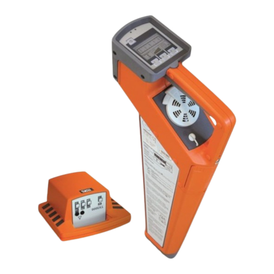
HT-5000 4 OPERATING INSTRUCTIONS 4.1 INSTRUMENT DESCRIPTION 4.1.1 Description of the receiver RX5000 Fig. 1: Description of the receiver RX5000 Item Description Control panel with display (see paragraph 4.1.2) Speaker with volume control The speaker plays back various acoustic signals (e.g. beeps... -
Page 6: Display And Control Panel Of Rx5000
HT-5000 4.1.2 Display and control panel of RX5000 Fig. 2: Display and control panel of RX5000 Item Description Light sensor Light sensitive photo cells to automatically regulate the display lighting The display lighting can be manually activated for one minute by briefly covering the light sensor... -
Page 7: Description Of Transmitter Tx5000
HT-5000 4.1.3 Description of transmitter TX5000 The TX5000 transmitter is distinguished by the following features: • Inductive coupling of the signal using the integrated antenna or transmitter clamp • Direct (galvanic) coupling of the signal using connected equipment (such as the measurement cable and power socket adapter) •... -
Page 8: Connection And Initial Use Of Transmitter Tx5000
HT-5000 4.2 CONNECTION AND INITIAL USE OF TRANSMITTER TX5000 4.2.1 Transmitter signals and operation modes The type and strength of the output signal can be configured by the user as follows to meet the specific requirements of either the line to be located or the site to be surveyed:... -
Page 9: Options For Direct And Inductive Signal Coupling
HT-5000 4.2.2 Options for direct and inductive signal coupling CAUTION If the transmitter is connected to electrical service cables, it has to be considered that the device is designed to achieve CAT II / CAT III 440 V and CAT IV 300 V with Class 2 protection (double insulation) according to IEC / EN 61010-1. - Page 10 HT-5000 Application Principle of coupling Single-wire lines or pipes (with or without insulation against earthing) The distance between the earth spike and the ends of the connected lines should be as great as possible There is a danger of the return...
-
Page 11: Coupling With Special Accessories
HT-5000 4.2.2.2 Coupling with special accessories The signal from the transmitter can be directly coupled into plug sockets, antenna connections coax and telephone jacks with the aid of a suitable adapter cable (Cod. 890008852). In doing so, it is not necessary to disconnect the lines. -
Page 12: Inductive Signal Coupling
HT-5000 4.2.2.3 Inductive signal coupling For lines which are not easily accessible, the signal from the transmitter has to be inductively coupled via the integrated antenna. The inductive coupling of the signal is highly recommended if unknown lines are to be located (e.g. at a construction site). - Page 13 HT-5000 Under certain circumstances lines at lower depths can 'hide' deeper, adjacent lines, thus making it more difficult to locate them. In such cases, the transmission characteristics of the transmitter TX5000 can be fully utilised and the lines which have already been located can be masked out (see Fig. 8) Fig.
-
Page 14: Signal Coupling In Non-Metallic Pipes
HT-5000 4.2.2.4 Signal coupling in non-metallic pipes With the aid of the FlexSonde GOK50-R the transmitter's signal can be transmitted through non-metallic pipes, as shown in the picture below: Fig. 9: Signal coupling in non-metallic pipes Alternatively, any other active probe (e.g. a camera probe) with adequate transmitting frequency can be located using the receiver. -
Page 15: Initial Use Of The Transmitter Tx5000
HT-5000 4.2.3 Initial use of the transmitter TX5000 Follow the steps listed below in order to prepare the transmitter to search for lines in conjunction with the receiver: Step Action Connect the transmitter to the line to be located using the most suitable method, or place the transmitter on the site to be searched see paragraph 4.2.2... -
Page 16: Use Of Receiver Rx5000
HT-5000 4.3 USE OF RECEIVER RX5000 4.3.1 Modes of operation for the receiver RX5000 If a TX5000 transmitter is not available, a site can also be probed by means of passive line location. The RX5000 receiver is capable of detecting radio signals in the frequency range between 15kHz to 23kHz as well as power signals in the frequency range between 50/60Hz. -
Page 17: Regulating The Sensitivity Level To Match The Reception Signal Strength
HT-5000 4.3.1.1 Regulating the sensitivity level to match the reception signal strength Reception signal strength and sensitivity are shown in the following segments of the display: Item Mode of operation Reception signal display bargraph The strength of the reception signal is represented by this bargraph scale. -
Page 18: Handling The Receiver And Locating The Line
HT-5000 4.3.1.2 Handling the receiver and locating the line In order to be able to determine the position and orientation of a metallic conductor, the following rules should be internalised and applied when locating lines. As shown in Fig. 11 the receiver should always be held in front of the body in an upright position and as close to the ground as possible. -
Page 19: Changing Of The System Settings
HT-5000 4.3.1.3 Changing of the system settings Proceed as follows to change the settings: Step Action Briefly press the button while continuing to hold down the until an audible signal is heard. The following image is display: Now one of the following depth measurement processes may be... -
Page 20: General Site Surveying
HT-5000 4.3.2 General site surveying A general site probing urgently needs to be conducted and there is inaccurate or no information available as to the location and orientation of metallic conductors on a site planned for construction (e.g. excavation work). -
Page 21: Determining The Direction Of A Line
HT-5000 4.3.3 Determining the direction of a line Step Action If the direction of the conductor will be determined with the aid of the TX5000 transmitter, couple the transmitter's signal onto the metallic conductor in such a way that there is as little signal loss as possible (see paragraph 4.2.2 and paragraph 4.3.1) -
Page 22: Determining The Depth Of A Line
HT-5000 4.3.4 Determining the depth of a line The RX5000 receiver has an automatic push key depth measurement feature. One precondition is that a clear signal from the TX5000 transmitter is coupled onto the conductor to be measured. For this procedure, the transmitter's signal has to be continuous (not pulsed) (see paragraph 4.2.1). - Page 23 HT-5000 With a steady grip, hold the receiver perpendicular to the position of a known metallic conductor, e.g. above a location which was marked during the site survey. The signal strength bargraph should show zero (see paragraph 4.3.2). In doing so, the tip of the receiver should...
- Page 24 HT-5000 During the depth measuring process, the following symbols are used to notify the user about certain characteristics and errors: Symbol Meaning For of one of the following reasons, the depth could not be measured: • The signal received was too weak or too irregular •...
-
Page 25: Functional Test Of The Receiver
(see next page): If this is the case, the error code should be forwarded to the service department of HT ITALIA Press the function key to exit the self-test EN - 24... - Page 26 Fault internal module L1. Contact service dept of HT ITALIA Fault internal module L2. Contact service dept of HT ITALIA Fault internal modules L1 and L2. Contact service dept of HT ITALIA Generic fault. Contact service dept of HT ITALIA...
-
Page 27: Maintenance
HT-5000 5 MAINTENANCE 5.1 REPLACEMENT FLOOR CAP OF THE RECEIVER RX5000 The plastic floor cap, which prevents the tip of the receiver from being damaged, can be easily replaced with the aid of a pointed object (e.g. screwdriver). Fig. 14: Replacement of the floor cap 5.2 REPLACEMENT BATTERIES OF RECEIVER RX5000... -
Page 28: Replacement Batteries Of Transmitter Tx5000
HT-5000 5.3 REPLACEMENT BATTERIES OF TRANSMITTER TX5000 The batteries in the transmitter TX5000 have to be replaced as soon as the red LED battery indicator starts to blink Should this occur while the user is busy locating a line with the receiver, he/she will be... -
Page 29: Technical Specification
HT-5000 6 TECHNICAL SPECIFICATION 6.1 TECHNICAL CHARACTERISTICS OF RECEIVER RX5000 Parameter Value Frequency ranges • Mode 1: Radio 15kHz ÷ 23kHz • Mode 2: Power network 50Hz / 60Hz • Mode 3: Transmitter 32.768kHz Sensitivity Refer to a depth of 1m •... -
Page 30: Technical Characteristics Of Transmitter Tx5000
HT-5000 6.2 TECHNICAL CHARACTERISTICS OF TRANSMITTER TX5000 Parameter Value Transmitted power (switchable) 0.1W / 0.5W Frequency 32.768kHz Power supply 6x1.5V batteries type IEC LR20 40 hours (for intermittent use with alkaline Battery life batteries, 20 °C) Working temperature according to IEC/EN60068-1 •... -
Page 31: Service
HT-5000 7 SERVICE 7.1 WARRANTY CONDITIONS This instrument is guaranteed for one year against material or production defects, in accordance with our general sales conditions. During the warranty period the manufacturer reserves the right to decide either to repair or replace the product.
Need help?
Do you have a question about the HT-5000 and is the answer not in the manual?
Questions and answers