Table of Contents
Advertisement
Quick Links
Advertisement
Table of Contents

Related Manuals for Micsig CP1003B


Summary of Contents for Micsig CP1003B
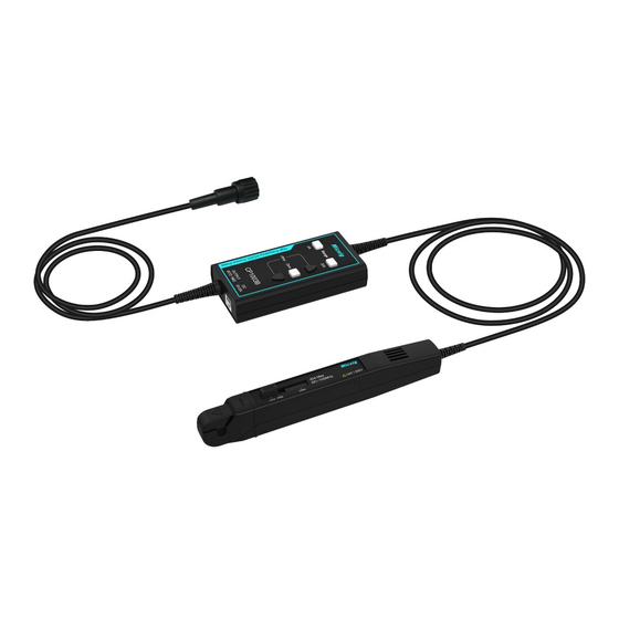
- Page 1 High Frequency AC / DC Current Probe CP1003B / CP503B User Manual www.micsig.com...
- Page 2 Micsig shall not be liable for errors or incidental or consequential damages arising out of the furnishing, use or application of this document or any information contained herein.
- Page 3 The content of the anti-counterfeiting label has been altered, or is blurred and unrecognizable. c. It has been dismantled by unauthorized personnel by Micsig (eg: changing wires, dismantling internal components). d. There is no sales voucher or the content of the sales voucher does not match the...
-
Page 4: Table Of Contents
Content General Safety Summary ………………………………………………………….. ii Maintenance Safety ………………………………………………………….. iv Compliance Information ………………………………………………………….. Safety Compliance Environmental Considerations Preface ………………………………………………………………………………….. Documentation Conventions used in this manual Factory Repair Main Functions …………………………………………………………………………… 2 Probe Structures .………………………………………………………………………. Probe Slider and Wire Grip Probe Control Module Installation ……………………………………………………………………………….. -
Page 5: General Safety Summary
Do not operate the product when it is suspected that the product is malfunctioning. Have it inspected by service personnel designated by Micsig. Keep away from exposed circuits. Do not touch exposed wiring and components while the power is on. -
Page 6: Maintenance Safety
Maintenance Safety Maintenance Safety Summary Only qualified service personnel with relevant qualifications should perform service operations. Please read this "Maintenance Safety Summary" and "General Safety Summary" before performing any repair operations. Do Not Serve Alone: Do not make internal repairs or adjustments to this product unless someone else is on site to provide first aid and resuscitation. -
Page 7: Compliance Information
Compliance Information Compliance Information This section lists the EMC (Electromagnetic Compatibility), safety and environmental standards to which the instrument complies. Safety Compliance Equipment Type Test and Measurement Equipment. Pollution Degree Description The micro-environmental pollution levels used to determine clearances or creepage distances can be classified into 4 levels. - Page 8 Compliance Information Overvoltage Class Description The overvoltage level is divided according to the IEC60664 standard, which is divided into four levels: CAT I, CAT II, CAT III, and CAT IV. * CAT I is a low-voltage low-energy class with protective devices, generally referring to the internal voltage of electronic equipment;...
-
Page 9: Environmental Considerations
Compliance Information Environmental Considerations This section provides information about the environmental impact of the product. Product End-of-Life Handling Observe the following guidelines when recycling an instrument or component: Equipment Recycling: Production of this equipment required the extraction and use of natural resources. The equipment may contain substances that could be harmful to the environment or human health if improperly handled at the product’s end of life. -
Page 10: Preface
The diagrams in this manual use the following symbols to indicate the sequence of steps: ①、②、③、④、⑤、⑥、⑦、⑧、⑨ Factory Repair If the probe requires service, the probe must be returned to Micsig. If the original packaging is unusable or missing, please follow the packaging guidelines below:... -
Page 11: Main Functions
AC and DC currents. It has the characteristics of high bandwidth and high precision, which can meet the needs of most test fields. Key features: >100 MHz bandwidth, ≤ 3.5ns rise time (CP1003B) * >50 MHz bandwidth, ≤ 7ns rise time (CP503B) *... -
Page 12: Probe Structures
Probe Structure Probe Structure Probe Slider and Wire Grip 1. When the slider is in the "LOCK" position, you can degauss the probe and take measurements. 2. Move the slider to the "OPEN" unlocked position to insert or remove the wire from the wire clip. -
Page 13: Probe Control Module
Probe Structure Probe Control Module The CP1003B and CP503B function buttons and LED status indicators are located on the probe control module and are described as below: Function Button The Range button is the range switching button, which can be selected between *... -
Page 14: Installation
Installation Installation Caution: The probe head is a precision part. Do not drop the probe or physically shock it, twist it, or drastically alter its surroundings. Do not insert wires larger than 5.0 mm in diameter into the probe grip, as this may damage the probe. Connecting to an oscilloscope 1. -
Page 15: Function Check And Basic Operation
Function Check and Basic Operation Function Check and Basic Operation CAUTION: Do not force wires larger than 5.0 mm in diameter into the probe jaws, as this may damage the probe. The mating surface of the probe head transformer is precisely polished and should be handled with care. Dirt on the mating surface of the probe head transformer may reduce measurement accuracy. -
Page 16: Applications
Application Reference Application Reference The high-frequency AC / DC current probe can be used in many measurement fields, such as new energy vehicle design, switching power supply design, electrical engineering, semiconductor device design, avionics design, inverter/transformer design, electronic ballast design, Industrial control/consumer electronics design, engine drive digital design, power electronics and power transmission practical design, etc. -
Page 17: Measuring Inductor Turns
Application Reference High impedance pulse source If the pulse source has a higher impedance of known resistance, and the output voltage drops as the current increases, the inductance of the coil can be calculated from the time constant of the charging curve. The current ramp shows how to derive the formula value for the inductance. - Page 18 Application Reference To get a more accurate number of turns, a coil with a known number of turns is needed as a reference. Do the following: 1. Repeat steps 1 and 2 above with the following changes: 2. Insert the reference coil into the current probe. 3.
-
Page 19: Technical Specifications
Warranted Characteristics, Typical Characteristics, Nominal Characteristics Warranted Characteristics Table 1: Warranted Electrical Characteristics Warranted characteristics describe performance guaranteed to be achieved within tolerances or required by a particular test type. Characteristics CP1003B CP503B Bandwidth DC-100MHz DC-50MHz Rise Time ≤ 3.5ns ≤... - Page 20 Specifications Figure 1: Maximum Current VS Frequency Curve CP503B CP1003B Warning: When measuring high-frequency current, be careful not to exceed the current value shown in the curve. Use of the maximum continuous current exceeding the curve will cause the probe to burn.
- Page 21 Technical Specifications Figure 3: Input Impedance VS Frequency Curve CP1003B Frequency (Hz) CP503B Frequency (Hz)
- Page 22 Technical Specifications Table 3: Environmental Characteristics Features Parameters Operating temperature 0~50℃ Storage temperature -20℃ ~80℃ 5%~95%(0~40℃ ,non-condensing) Operating humidity 5%~65%(40℃ ~50℃ ,non-condensing) Working height ≤ 3000m Storage height ≤ 12000m Table 4: Mechanical Characteristics Features Parameters 17.5x2x2.9cm Probe head size Probe Control Module Dimensions 10.8*5.6*2.6cm Maximum conductor diameter...
-
Page 23: Nominal Characteristics
Technical Specifications Nominal Characteristics Table 5: Nominal Characteristics Nominal characteristics describe guaranteed characteristics, but these characteristics are not subject to tolerance limits. Features Parameter Input coupling Range 6A (2X) / 30A (10X) 1V/2A(6A ) Output sensitivity 1V/10A(30A) Terminals Connect the output terminals to 1MΩ Compatible with any BNC interface Compatibility oscilloscopes... -
Page 24: Maintenance
If the probe does not work on other channels or on the oscilloscope, the probe may be defective, please contact the Micsig after-sales department for repair. -
Page 25: Cleaning
Do not use abrasives on any part of the probe. * Micsig reserves the right of final interpretation for the content hereinabove; * It is subject to update without prior notice;...
Need help?
Do you have a question about the CP1003B and is the answer not in the manual?
Questions and answers