
Related Manuals for Micsig SigOFIT OIP Series


Summary of Contents for Micsig SigOFIT OIP Series
- Page 1 SigOFIT Optical-fiber Isolated Probe Quick Guide (OIP series) Shenzhen Micsig Technology Co., Ltd. www.micsig.com...
- Page 2 WARNING DO NOT block the heat dissipation port on the back of Optical-Electrical converter, otherwise the probe may be overheated and damaged. DO NOT excessively bend the fiber cable. Avoid tight radius (<8cm) bends, crushing, crimping, twisting, pulling or otherwise stressing the cable. SigOFIT™...
-
Page 3: Main Steps
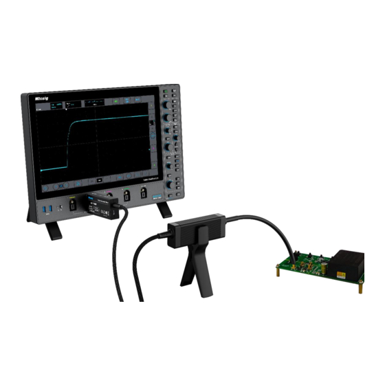
Main Steps: 1. Connect the Optical-Electrical (O-E) converter to oscilloscope (Figure 1); O-E Converter Figure. 1 2. Set the oscilloscope input impedance to 50Ω, set corresponding attenuation ratio and delay time on the oscilloscope; Connect attenuating tip to the Electrical–Optical (E-O) converter (Figure 2); Figure. - Page 4 4. Power the SigOFIT probe by connecting USB-C cable to O-E Converter using standard charger (localized); 5. Solder the MCX or MMCX connector to the test board: 1) When testing Vgs signal, the signal pin (in the middle) of the MMCX female connector must be connected to the G-end of the MOSFET;...
-
Page 5: Button Descriptions
Quick Guide Over-voltage Warning: *When “Gain” button flashes and hearing a rapid "DiDiDiDi.." buzzer sound, indicate a over- voltage warning, please select a suitable attenuating tip. Over-heating Warning: *When hearing a “DiDi" sound every 2 seconds, it means the temperature of the Optical- Electrical (O-E) converter is overheated, please check whether the dissipation port is blocked. - Page 6 ±625V OP500-2 50:1 @20dB ±62.5V 1000:1 @0dB ±1250V OP1000-2 100:1 @20dB ±125V 2000:1 @0dB ±2500V OP2000-2 200:1 @20dB ±250V * Please refer to User Manual or contact Micsig for more information. Shenzhen Micsig Technology Co., Ltd Email: sales@micsig.com Tel: +86-755-88600880...
Need help?
Do you have a question about the SigOFIT OIP Series and is the answer not in the manual?
Questions and answers