
Related Manuals for Micsig SigOFIT MOIP100P


Summary of Contents for Micsig SigOFIT MOIP100P
- Page 1 SigOFIT Optical-Fiber Isolated Probe USER MANUAL Version updated: March 20, 2024 Shenzhen Micsig Technology Co. Ltd...
- Page 2 Micsig shall not be liable for errors or for incidental or consequential damages arising out of the furnishing, use or application of this document or any information contained herein.
-
Page 3: Warranty
SigOFIT Optical-fiber Isolated Probe User Manual Warranty Micsig warrants that this product will be free from defects in materials and workmanship for a period of one (1) year from the date of shipment. If any such product proves defective in materials or workmanship during this warranty period, Micsig, at its option, either will repair the defective product without charge for parts and labor, or will provide a replacement in exchange for the defective product. -
Page 4: Table Of Contents
UTO CALIBRATION AND MANUAL TECHNICAL SPECIFICATIONS ............................17 MAINTENANCE SERVICE ..............................22 ....................................22 ROUBLESHOOTING ......................................22 AINTENANCE ORDERING INFORMATION .............................. 23 ........................................23 ODELS ..................................23 TANDARD CCESSORIES AFTER SALES SERVICE / SERVICE SUPPORT ......................25 4 / 25 www.micsig.com... -
Page 5: General Safety Summary
Connect and disconnect the equipment properly. • Only use the testing wires and accessories that are provided with the product or specified by Micsig. • Before connecting the probe to the circuit under test, connect the probe output terminal to the oscilloscope. -
Page 6: Maintenance Safety Summary
Caution when servicing with electricity: Dangerous voltages or currents may be present in this product. Disconnect the power and test leads before removing the protective panel and performing soldering or component replacement. To avoid electric shock, do not touch the exposed connectors. 6 / 25 www.micsig.com... -
Page 7: Compliance Information
Category II. Circuits directly connected to the building wiring at utilization points (socket outlets and similar points). Category III. In the building wiring and distribution system. Category IV. At the source of the electrical supply to the building. Overvoltage category Overvoltage category II 7 / 25 www.micsig.com... -
Page 8: Environmental Notes
This symbol indicates that the product complies with the relevant requirements of the EU Directives 2012/96/EC and 2006/66/EC on Waste Electrical and Electronic Equipment (WEEE) and Batteries. 8 / 25 www.micsig.com... -
Page 9: Introduction
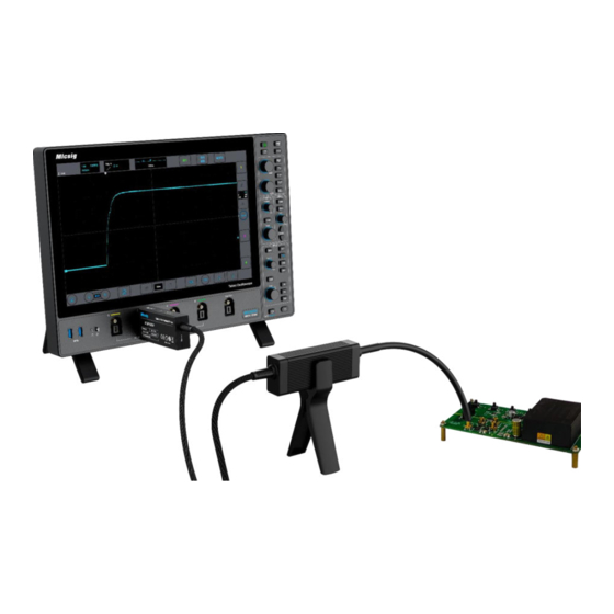
SigOFIT Optical-fiber Isolated Probe User Manual Introduction The Micsig SigOFIT optical-fiber isolated probe offers a galvanically isolated measurement solution for accurately resolving high bandwidth, high voltage differential signals in the presence of large common mode voltages with the excellent common mode rejection capability within its bandwidth range. -
Page 10: Probe Description
Over-heating Warning: When hearing a <DiDi" sound every 2 seconds, it means the temperature of the Optical-Electrical (O-E) converter is overheated, please check whether the dissipation port is blocked. 10 / 25 www.micsig.com... -
Page 11: Electrical-Optical Converter
Attenuation ratio of 2000:1 OP2000 Attenuation ratio of 5000:1 OP5000 Attenuation ratio of 10000:1 OP10000 Install the attenuating tip As shown in the figure below, screw the attenuating tip into the E-O converter end till firmly tightened. 11 / 25 www.micsig.com... - Page 12 Please select the attenuating tip with the lowest attenuation ratio allowed by the tested signal range. The attenuator should be selected based on the peak voltage (or rms voltage) of the signal under test. Please refer to the technical specifications to select the appropriate attenuator. 12 / 25 www.micsig.com...
-
Page 13: Precaution Requirements
Please check damage to the fiber cable, (as shown below) please stop use when there is damage to the flexible braided cable or the soft rubber sheath. When not in use, store the SigOFIT probe in its factory fitted carrying case. 13 / 25 www.micsig.com... -
Page 14: Environmental Requirements
Safe distance from electro-optical converters and attenuators when measuring high-voltage common-mode signals: Common model voltage (AC) 10kV or below 10 kV ~ 35 kV > 35 kV Safe distance >0.7m >1m >1.5m 14 / 25 www.micsig.com... - Page 15 Warning: To prevent arc flash caused by different potentials, do not place the electrical-optical converter end attenuator in a circuit with different voltages. 15 / 25 www.micsig.com...
-
Page 16: Installation
The SigOFIT probe has auto-calibration function that automatically corrects the gain accuracy. Always press Cali. button to get better results before get final test readings. No need to disconnect the test during calibration. Auto calibration can be completed in 1 second. 16 / 25 www.micsig.com... -
Page 17: Technical Specifications
0°C to 40°C (operating), -20°C to +70°C (non-operating) Humidity 5% to 85% RH (non-condensing), 75% RH above 30°C, 45% RH above 40°C Altitude 3000 m (operating), 12,000 m (non-operating) Usage Indoor Use Only Package size 37*11*32.5 cm Package GW 2.2KG 17 / 25 www.micsig.com... - Page 18 20.98MΩ || 1pF 50:1 @20dB ±62.5V 1000:1 @0dB ±1250V OP1000-3 2500Vpp 20.94MΩ || 1pF 100:1 @20dB ±125V 2000:1 @0dB ±2500V OP2000-3 2500Vpp 20.52MΩ || 1pF 200:1 @20dB ±250V 5000:1 @0dB ±6250V OP5000-3 8000Vpp 40.82MΩ|| 2.4pF 500:1 @20dB ±625V 18 / 25 www.micsig.com...
- Page 19 20.94MΩ || 1pF 100:1 @20dB ±50V 2000:1 @0dB ±1000V OP2000-1G 2500Vpp 20.52MΩ || 1pF 200:1 @20dB ±100V 5000:1 @0dB ±2500V OP5000-1G 3600Vpp 40.92MΩ || 1pF 500:1 @20dB ±250V 10000:1 @0dB ±5000V OP10000-1G 8000Vpp 40.82MΩ|| 2.4pF 1000:1 @20dB ±500V 19 / 25 www.micsig.com...
- Page 20 <3000 Vpp MCX coaxial lead <8000 Vpp LCX coaxial lead Mechanical characteristics Characteristics Parameters Optical-Electrical (O-E) converter size 9.8 x 4.5 x 2.1 cm Electrical–Optical (E-O) 11 x 4 x 2.3 cm converter size Optical cable length 20 / 25 www.micsig.com...
- Page 21 SigOFIT Optical-fiber Isolated Probe User Manual Amplitude and frequency characteristics curve ▲Amplitude-frequency characteristics of different SigOFIT probes Attenuating tip CMRR ▲ Common mode rejection capabilities of different attenuators (0dB) at various frequencies. 21 / 25 www.micsig.com...
-
Page 22: Maintenance Service
Do not wipe the probe with chemical cleaners. Clean the outer surface of the probe with a dry, non-linting soft cloth or a soft bristle brush. When not in use, store the SigOFIT probe in the suitcase provided by Micsig. 22 / 25... -
Page 23: Ordering Information
SigOFIT Optical-fiber Isolated Probe User Manual Ordering Information Models MOIP100P Micsig SigOFIT 100MHz, Optical-fiber Isolated Probe, 2-meter cable MOIP200P Micsig SigOFIT 200MHz, Optical-fiber Isolated Probe, 2-meter cable MOIP350P Micsig SigOFIT 350MHz, Optical-fiber Isolated Probe, 2-meter cable MOIP500P Micsig SigOFIT 500MHz, Optical-fiber Isolated Probe, 2-meter cable... - Page 24 OP10-2,OP20-2,OP50-2 OP20-2 OP100-2,OP200-2,OP500-2 MOIP200P OP1000-2,OP2000-2,OP5000-2 OP10-3,OP20-3,OP50-3 OP20-3 MOIP350P OP100-3,OP200-3,OP500-3 OP1000-3 OP1000-3,OP2000-3,OP5000-3 OP10-5,OP20-5,OP50-5 OP50-5 MOIP500P OP100-5,OP200-5,OP500-5 OP2000-5 OP1000-5,OP2000-5,OP5000-5 OP10-1G,OP20-1G,OP50-1G MOIP800P OP100-1G,OP200-1G,OP500-1G OP50-1G OP2000-1G OP1000-1G,OP2000-1G,OP5000-1G MOIP1000P OP10000-1G Supported Oscilloscopes Any oscilloscope with standard BNC interface and 50Ω impedance. 24 / 25 www.micsig.com...
-
Page 25: Standard Accessories
Micsig provides one-on-one exclusive technical support service. During the warranty period, Micsig will be responsible for providing free maintenance for any malfunctions caused by quality issues within the normal use of the product that have not been disassembled or repaired.
Need help?
Do you have a question about the SigOFIT MOIP100P and is the answer not in the manual?
Questions and answers