Table of Contents
Advertisement
Quick Links
DIGITAL MIXER
Thank you for purchasing TOA's Digital Mixer.
Please carefully follow the instructions in this manual to ensure long, trouble-free use of your equipment.
TABLE OF CONTENTS
........................................................................... 2
............................................................ 3
.......................................................................... 5
..................................................................................... 10
........................................................................................ 11
.................................................................... 12
..................................................................... 16
....................................................................... 17
............................................................................. 18
...................................................................... 18
............................................................................. 20
..................................................................... 22
........................................................................... 23
............................................................................................ 23
................................................................................ 24
....................................................................................... 24
OPERATING INSTRUCTIONS
D-2000 Series
(Version 4)
........................... 13
............................................ 14
................................................. 15
.............. 19
..................................... 19
.............................. 21
................................................ 21
Advertisement
Table of Contents

Related Manuals for Toa Q-D-2012C


Summary of Contents for Toa Q-D-2012C
-
Page 1: Table Of Contents
OPERATING INSTRUCTIONS DIGITAL MIXER D-2000 Series (Version 4) Thank you for purchasing TOA's Digital Mixer. Please carefully follow the instructions in this manual to ensure long, trouble-free use of your equipment. TABLE OF CONTENTS 1. HANDLING PRECAUTIONS ................2 2. NOMENCLATURE AND FUNCTIONS 2.1. -
Page 2: Handling Precautions
For details on how to update the firmware, read the separate Setting Software Instructions, "Method to Enable Communications between the PC and the Unit." The latest versions of the D-2000 Setting Software and Instruction Manual are made available on the TOA product data download site (http://www.toa-products.com/international/). -
Page 3: Nomenclature And Functions 2.1. D-2008Sp Digital Mixing Processor Unit
2. NOMENCLATURE AND FUNCTIONS 2.1. D-2008SP Digital Mixing Processor Unit The D-2008SP Digital Mixing Processor Unit is designed to have up to 32 audio inputs and outputs in total. A built-in multiple signal processing functions permit the unit to be used as both a mixer and a signal processor. - Page 4 1. Power switch [POWER ON/OFF] 14. Selection keys Power is switched on and off with each Use the Up and Down keys to select the Item depression of this switch. selection indicator. Use the Left and Right keys to select the preset 2.
-
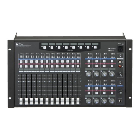
Page 5: D-2012C Remote Console Unit
If both indicators light or remain unlit after the unit activation is complete, cycle the power. If the situation does not change after the unit power-up, the unit may break down. Contact your TOA dealer. 2.2. D-2012C Remote Console Unit The D-2012C is designed to be used with the D-2008SP Digital Mixing Processor. - Page 6 • A-Section • B-Section 1. Power switch 4. Key lock indicator Power is switched on and off with each Lights red when the operation keys or knobs are depression of this switch. locked. 2. Power indicator 5. Write-in space Lights when the power is switched on. Write the name of the function assigned to the key, etc.
- Page 7 • C-Section 7. Level indicators [PEAK, +12 dB, 0 dB, –40 dB] 9. Channel ON/OFF keys Indicate signal levels for each channel. Pre-fader Turn on or off the output for each channel. value is indicated for input channels and post- Pressing a key causes it to light and the signal of fader value for output channels.
- Page 8 • D-Section Note: Refer to p. 7 for names and functions of parts 7 – 10. 12. Rotary encoders (1 – 8) Adjust the volume of each input or output channel. The volume increases as the encoder is rotated clockwise, and decreases as it is rotated counterclockwise.
- Page 9 • E-Section 13. Line input signal level indicators [SIGNAL, PEAK] Display the signal level set with the Line input volume control (15). The SIGNAL indicator lights when a signal exceeding the reference level of –20 dB is fed to the line input terminal. If a signal at the line input terminals clips, the PEAK indicator lights.
-
Page 10: D-911 Vca Fader Unit
2.3. D-911 VCA Fader Unit The D-911 VCA Fader Unit is designed for use with the D-2008SP. Connecting to the D-984VC VCA Control Module installed in the D-2008SP permits volume adjustment of input and output channels and contact controls of the D-2008SP. For details, refer to the instruction manual enclosed with the D-911. -
Page 11: Operations 3.1. D-2008Sp Operation
3. OPERATIONS 3.1. D-2008SP Operation Using the front panel-mounted keys, preset memories can be recalled, and input or output channel to be monitored can be selected. Input or output channel can be monitored through headphones connected to a front panel-mounted headphone jack. -
Page 12: Recalling Preset Memories
3.1.1. Recalling preset memories Follow the procedure below to recall each parameter setting stored as preset memory* using the D-2000 Setting Software or D-2012C Remote console unit. Note When multiple D-2008SP and D-2012C units are installed in the system, the D-2008SP with ID1 must be included to simultaneously operate other units in the system through the following operation. -
Page 13: Selecting The Input Or Output Channel To Be Monitored
3.1.2. Selecting the input or output channel to be monitored D-2008SP's input or output channels in operation can be monitored. Step 1. Press the Selection key " " or " " several times to light "MONITOR" (Item selection indicator). MONITOR Lights Step 2. -
Page 14: Selecting The D-2012C's Monitor Channels
3.1.3. Selecting the D-2012C's monitor channels The line input and headphone output of the D-2012C Remote Console connected to the D-2008SP processor's Monitor bus terminal can be monitored. Note Before selecting, connect the D-2008SP's Monitor bus terminal to the D-2012C's Monitor bus terminal and perform console settings using the D-2000 Setting Software. -
Page 15: Selecting Cobranet's Monitor Channels
3.1.4. Selecting CobraNet's monitor channels When the D-2000CB CobraNet Interface Module has been inserted into the D-2008SP and connected to other CobraNet equipment, CobraNet's input and output channel preprogrammed using the D-2000 Setting Software can be monitored. Step 1. Press the Selection key " " or “ " several times to light CobraNet "CobraNet"... -
Page 16: Key Lock Function On/Off
3.1.5. Key lock function ON/OFF Enabling the key lock function disables the following operations made on the D-2008SP's front panel. • Recalling preset memories • Selecting the input or output channel to be monitored • Selecting the D-2012C's monitor channels •... -
Page 17: D-2012C Operation
3.2. D-2012C Operation 3.2.1. Key-assignable functions The following functions can be assigned to the D-2012C's function keys. The function keys are explained on the following pages using the name of the function assigned to each key (example: Memory key). Note To implement the following functions (except Stereo Input) with the function key operation, the D-2008SP with ID1 must be included in the system. -
Page 18: Preset Memory Recall
3.2.2. Preset memory recall Each parameter stored as preset memory using the D-2000 Setting Software or the D-2012C can be recalled. [Operation] Pressing the Memory key switches the operation panel settings to the setting status Memory 1 stored under the designated preset memory number. In this event, the depressed key lights. -
Page 19: Switching Line Inputs (Valid Only When The D-936R Or D-937Sp Module Is Installed)
3.2.4. Switching Line Inputs (valid only when the D-936R or D-937SP module is installed) This function switches the line inputs (In 1 – 4) of the D-936R Stereo Input Module or the D-937SP Digital Input Module. [Operation] Pressing the Line Input key selects the designated line (stereo) input. Line Input 4 In this event, the depressed key lights. -
Page 20: Fader Layer Switching
3.2.6. Fader layer switching There are 12 motorized faders and 8 rotary encoders on the D-2012C's operation panel. Store a combination of their channel assignments as a single fader layer in advance using the D-2000 Setting Software. Since 4 different fader layers can be set, up to 4 channels can be assigned to each motorized fader and rotary encoder. -
Page 21: D-2008Sp Control Output On/Off (Console Switch)
3.2.7. D-2008SP control output ON/OFF (console switch) Enables or disables the contact output of the D-981 or D-983 Remote Control Module installed in the D- 2008SP Digital Mixing Processor. The contact output terminals assigned to the "Console switch" using the D- 2000 Setting Software can be operated. -
Page 22: Key Lock Function On/Off
3.2.9. Key lock function ON/OFF Setting the Key Lock function to ON allows operation of the following keys to be disabled: the D-2012C's operation panel-mounted function keys (except the Key Lock key), motorized faders, rotary encoders, Monitor Channel Selection keys, and Channel ON/OFF keys. Key lock indicator (Lockable operation section) D-2012C... -
Page 23: Monitor Channel Clear
3.2.10. Monitor channel clear This function clears the selection of all the monitor channels assigned to the monitor bus to which the D- 2012C in operation is connected. [Operation] If the Monitor Clear key is pressed, the selection of monitor channels is cleared and the Monitor Clear depressed key lights. -
Page 24: D-911 Operation
3.3.2. Contact control Preset memory recall, Volume level up and down functions can be assigned to the D-984VC's contacts using the D-2000 Setting Software. Assigned functions can be implemented by pressing the Control keys 1 – 8. URL: http://www.toa.jp/ 133-22-166-6B...
Need help?
Do you have a question about the Q-D-2012C and is the answer not in the manual?
Questions and answers