Table of Contents

Related Manuals for Toa CX-124


Summary of Contents for Toa CX-124
-
Page 1: Mixing Console
Operating Instructions CX-124 MIXING CONSOLE CX-164 Please follow the instructions in this manual to obtain the optimum results from these units. We also recommend you to keep this manual handy for future re- ference. TOA Corporation KOBE, JAPAN... -
Page 2: Table Of Contents
Panel facilities Front panel [Channel input section] [Aux Return input/Stereo IN input section] [Output section] Rear panel Connection diagram for CX-124 and CX-164 Assembling input transformers Specifications for input transformers Input and output specifications Characteristic diagrams Block diagram Level diagram... -
Page 3: General Description
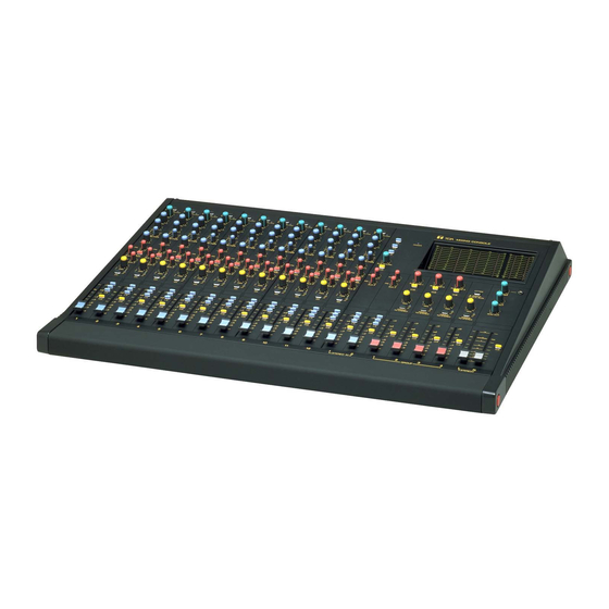
General description The TOA CX-124 is a mixing console with 12 input channels, 4 Group outputs, 1 Stereo output (L-R) and 1 Sum output, and the TOA CX-164 is a mixing console with 16 input channels, 4 Group outputs, 1 Stereo output (L-R) and 1 Sum output. -
Page 4: Panel Facilities
Panel facilities (Front panel) [Channel input section] Pad Switch [PAD] Pad switch inserts a –20 dB pad ahead of the head amplifier. Adjust the PAD switch, depending on the output level of microphones or associated equipment. Signal/Peak LED Indicator [SIG/PEAK] The dual color LED indicator lights green when the pre-EQ signal level reaches 20 dB before from nominal level, and turns red when the signal level reaches 6 dB below clip- ping, giving a visual reference for optimum setting of the trim control. - Page 5 Aux 1 Control [AUX 1] This control determines the level of the pre-EQ and pre-fader input signal to be fed to the Aux 1 buss. The position provides nominal level. Aux 2 Control [AUX 2]/Pre-fader, Post-fader Select Switch This control determines the level of the input signal to be fed to the Aux 2 buss. The Aux 2 control is associated with the pre-post EQ and fader selector switch, which permits its assign to be either pre or post EQ and fader.
-
Page 6: [Aux Return Input/Stereo In Input Section]
[Aux Return input/Stereo IN input section] Power LED indicator [POWER] The green LED indicator lights when the power switch is set to "on" position. Aux Return Assign Switch [1·2, 3·4, L·R] This switch selects the buss the signal input to Aux Return is to be transmitted to. The signal can be transmitted to the Group 1 and 2, or 3 and 4, or Stereo L and R busses. -
Page 7: [Output Section]
[Output section] STEREO GROUP – 7 –... - Page 8 Aux Send Control [AUX SEND 1, 2, 3] This control is provided to adjust the overall signal level of the aux mix to the Aux Send outputs. The position provides nominal level. Cue Switch [CUE] The Cue switch is for monitoring the pre-Aux send control signal through Headphones and Cue out- put.
-
Page 9: Rear Panel
Panel facilities (Rear panel) Channel Input Connector [LOW-Z] The XLR-type input connectors are electronically balanced with a nominal level of –60 dB and an im- pedance of 600 ohms, and will accept signals from –60 dB to 0 dB. Phantom powering is provided for use with condenser-type microphones (see PHANTOM), and once again the proper adjustment of Pad and Trim control [PAD/TRIM] and input fader will insure optimum signal to noise ratio and mini- mum distortion. - Page 10 Stereo Input Jack [STEREO IN] These RCA pin jacks are unbalanced, with a nominal of –10 dB and an impedance of 10k ohms. The Stereo input jacks should be connected to an outboard stereo unit (ie., Tape deck, CD player). Cue Output Jack [CUE OUT] These 1/4"...
-
Page 11: Connection Diagram For Cx-124 And Cx-164
Connection diagram for CX-124 and CX-164 Tapedeck for play back Effector etc. Microphone Power amplifier Power amplifier Tapedeck for recording Monitor speaker Main speaker – 11 –... -
Page 12: Assembling Input Transformers
Assembling input transformers The CX-124 and the CX-164 are designed with the electronically balanced inputs, however, optional in- put transformer IT-M4CX (for microphone input) or IT-L4CX (for microphone or line inputs) can be built- in the consoles, and their specifications are changed into the transformer input system. The input trans- former is used only for four channels. -
Page 13: Input And Output Specifications
Input and output specifications INPUT SPECIFICATIONS Contents in ( ) stand for CX-164 data. Input TRIM ON[20dB] LOW-Z CH INPUT –40 Mics or Lines 1~12 (16) HIGH-Z [0dB] ACCESSORY IN 1~12(16) STEREO IN L, R 1, 2 AUX RETURN L, R/MONO OUTPUT SPECIFICATIONS Output GROUP OUT 1~4... -
Page 14: Block Diagram
Block diagram – 14 –... -
Page 15: Level Diagram
Level diagram – 15 –... -
Page 16: General Specifications
Dimensional diagrams CX-124 Phantom Power +24V DC AC Line Voltage AC Mains, 50/60 Hz Power Consumption CX-124 48 W CX-164 52 W Weight CX-124 23 kg (50.7 Ib.) CX-164 27 kg (59.5 Ib.) Specifications are subject to change without notice.
Need help?
Do you have a question about the CX-124 and is the answer not in the manual?
Questions and answers