Table of Contents

Related Manuals for Toa D-2012C


Summary of Contents for Toa D-2012C
- Page 1 INSTALLATION MANUAL DIGITAL MIXER D-2000 Series (Version 4) D-2008SP D-2012C/ 2012AS Thank you for purchasing TOA's Digital Mixer. Please carefully follow the instructions in this manual to ensure long, trouble-free use of your equipment.
-
Page 2: Table Of Contents
4.2. Connection Example 2 ..................34 4.3. Removable Terminal Plug Connection ............. 35 4.4. Connecting the Monitor Bus Terminal of the D-2008SP and D-2012C .... 36 4.5. Audio Monitor Line Connection When Multiple Units Are Connected ....37 4.6. D-2012C's AC Power Cord Connection ............ - Page 3 .......... 46 5. PC CONNECTIONS ..................47 6. RETURNING SETTINGS TO THEIR INITIAL FACTORY DEFAULT (D-2008SP ONLY) .................... 48 7. FIRMWARE UPDATE PROCEDURE (D-2012C ONLY) ....... 49 8. OPERATIONS 8.1. D-2008SP Operation ..................51 8.1.1. Recalling preset memories ..............52 8.1.2.
- Page 4 11.12. D-971M Line Output Module ................78 11.13. D-971E Line Output Module ................78 11.14. D-971R Line Output Module ................78 11.15. D-2000DA1 Line Output Module ..............79 11.16. D-972AE Digital Output Module ..............79 11.17. D-961SP Digital Output Module ..............
-
Page 5: Handling Precautions
D-2008SP should not exceed +40 ºC (104 ºF). Failure to do so may shorten the product life. • When mounting the D-2012C in an equipment rack, be sure to mount a perforated panel larger than 1U size* above the unit. -
Page 6: Nomenclature And Functions 2.1. D-2008Sp Digital Mixing Processor Unit
Operation can be performed through the front key operation and from a PC with the D-2000 Setting Software installed. The D-2012C Remote Console Unit, when connected, remotely controls the D-2008SP's basic operations such as volume control. It can be mounted in an EIA component rack (3U size*). - Page 7 1. Power switch [POWER ON/OFF] 14. Selection keys Power is switched on and off with each Use the Up and Down keys to select the Item depression of this switch. selection indicator. Use the Left and Right keys to select the preset 2.
- Page 8 Note If both indicators light or remain unlit after the unit activation is complete, cycle the power. If the situation does not change after the unit power-up, the unit may break down. Contact your TOA dealer. [Rear] 34 35 36 37 27.
- Page 9 An audio transmission connector for the D- 2012C * The inherent address assigned to each network Connects to the D-2012C's Monitor bus terminal. component, expressed in 12-digit hexadecimal Audio signals are output to the D-2012C's notation. headphone jack through the monitor bus or audio signals from the D-2012C's Line input terminal 35.
-
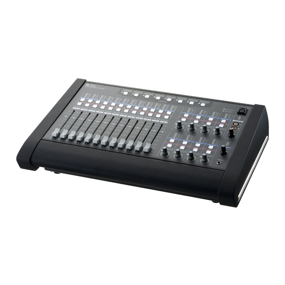
Page 10: D-2012C Remote Console Unit
2.2. D-2012C Remote Console Unit The D-2012C is designed to be used with the D-2008SP Digital Mixing Processor. The D-2012C can be LAN- connected to the D-2008SP Processor to allow remote operation of input and output channel volume adjustment, signal level monitoring, contact control and preset memory recall, etc. The D-2012C is equipped with line inputs and audio monitor bus terminal. - Page 11 • A-Section • B-Section 1. Power switch 4. Key lock indicator Power is switched on and off with each Lights red when the operation keys or knobs are depression of this switch. locked. 2. Power indicator 5. Write-in space Lights when the power is switched on. Write the name of the function assigned to the key, etc.
- Page 12 • C-Section 7. Level indicators [PEAK, +12 dB, 0 dB, –40 dB] 9. Channel ON/OFF keys Indicate signal levels for each channel. Pre-fader Turn on or off the output for each channel. value is indicated for input channels and post- Pressing a key causes it to light and the signal of fader value for output channels.
- Page 13 • D-Section Note: Refer to p. 12 for names and functions of parts 7 – 10. 12. Rotary encoders (1 – 8) Adjust the volume of each input or output channel. The volume increases as the encoder is rotated clockwise, and decreases as it is rotated counterclockwise.
- Page 14 • E-Section 13. Line input signal level indicators [SIGNAL, PEAK] Display the signal level set with the Line input volume control (15). The SIGNAL indicator lights when a signal exceeding the reference level of –20 dB is fed to the line input terminal. If a signal at the line input terminals clips, the PEAK indicator lights.
- Page 15 [Connection panel] 19. Functional earth terminal 23. Reset switch Note: This terminal is not for protective earth. Avoid touching this switch, as it is used only during maintenance. 20. AC Inlet Connect this inlet to the wall AC outlet using the 24.
- Page 16 2.3. D-911 VCA Fader Unit The D-911 VCA Fader Unit is designed for use with the D-2008SP. Connecting to the D-984VC VCA Control Module installed in the D-2008SP permits volume adjustment of input and output channels and contact controls of the D-2008SP. For details, refer to the instruction manual enclosed with the D-911.
- Page 17 [Rear] 6. Remote (activation) output terminals 7. VCA control module connection terminals Setting the Remote (activation) switch (3) to the These terminals are used exclusively for the D- ON position closes the output. 984VC VCA Control module. Use an RJ45 connector for connection.
-
Page 18: Optional Modules
2.4. Optional Modules Notes • Make sure that the power is switched OFF before attaching or detaching modules. • To avoid failures due to static electricity, do not touch the parts or terminals on the circuit board of both the unit and module. -
Page 19: D-922F Microphone/Line Input Module
2.4.3. D-922F Microphone/Line Input Module 5. Monaural input terminal [1, 2] (XLR-3-31 equivalent) Electronically-balanced input terminal. 2: Hot (Pin 1: Ground, Pin 2: Hot, Pin 3: Cold) Use XLR-3-12C or equivalent for connection. 3: Cold OFF : PHANTOM NORMAL LIFT : GND LINE 1: Ground +4dB(LINE) -
Page 20: D-2000Ad1 Microphone/Line Input Module
2.4.5. D-2000AD1 Microphone/Line Input Module LIFT LIFT LIFT LIFT 9. Monaural input terminal [1, 2, 3, 4] (XLR-3-31 or equivalent) Electronically balanced input terminal. 2: Hot (Pin 1: Ground, Pin 2: Hot, Pin 3: Cold) Use XLR-3-12C or equivalent for connection. 3: Cold Input sensitivity (–50/–36/–10/+4 dB) and phantom power (+48 V) ON/OFF settings can be performed by a PC using the D-2000 Setting software... -
Page 21: D-936R Stereo Input Module
2.4.6. D-936R Stereo Input Module Note This module cannot be used as a monitor input. 11. Stereo input terminal [1L/1R, 2L/2R, 3L/3R, 4L/4R] Unbalanced, RCA jack stereo input terminals. Either a single stereo input can be selected from the 4 available stereo inputs or all 4 stereo channels can be mixed. -
Page 22: D-971M Line Output Module
2.4.9. D-971M Line Output Module 15. Monaural output terminal [1, 2, 3, 4] (XLR-3-32 equivalent) Electronically-balanced output terminal. 1: Ground (Pin 1: Ground, Pin 2: Hot, Pin 3: Cold) Output signal level: +4 dB 3: Cold Use XLR-3-11C or equivalent for connection. 2: Hot 2.4.10. -
Page 23: D-2000Da1 Line Output Module
2.4.12. D-2000DA1 Line Output Module 18. Monaural output terminal [1, 2, 3, 4] (XLR-3-32 equivalent) Balanced (electronically-balanced) or unbalanced output, switchable. [Balanced output mode] • Balanced output mode (factory preset) (Pin 1: Ground, Pin 2: Hot, Pin 3: Cold) 1. Ground •... -
Page 24: D-972Ae Digital Output Module
2.4.13. D-972AE Digital Output Module 18. AES/EBU digital output terminal [AES/EBU, 1/2, 3/4] (XLR-3-32 or its equivalent) DIGITAL OUT Digital output terminal of AES/EBU format. 1: Ground (Pin 1: Ground, Pin 2: Signal, Pin 3: Signal) Use the XLR-3-11C or equivalent for 3: Signal connection. -
Page 25: D-983 Remote Control Module
2.4.16. D-983 Remote Control Module 23. Contact input terminal [CTRL IN, 1-6, 7-12, 13-18, 19-24] CTRL IN Six-circuit RJ45 contact input terminals. Pin No. 1 – 6 7 – 12 13 – 18 19 – 24 CTRL OUT CTRL IN Individual contact functions are assigned IN 1 IN 7... -
Page 26: D-2000Cb Cobranet Interface Module
• Be sure to connect both the Primary and Secondary terminals to a switching hub. • After connection completion, press the D-2008SP's front-mounted Reset switch to restart the D-2008SP. • Concerning a switching hub, contact TOA dealer. 30. Indicators LED name... -
Page 27: Installation
3. INSTALLATION 3.1. Inserting the D-2000CB To prevent a fire or electric shock, never open nor remove the unit WARNING case, as there are high voltage components inside the unit. Refer all servicing to qualified service personnel. Be sure to install the D-2000CB first before inserting other modules into the slots. Step 1. - Page 28 Step 4. Insert the D-2000CB's connector into the D-2008SP's internal connector. Terminal pins of the connector are exposed on the solder side of CAUTION the D-2000CB board. Never touch these terminal pins when inserting the connector to prevent finger injury. Step 5.
-
Page 29: Rack Mounting
Do not use them for other racks. When installing the unit in a rack other than that of TOA, be sure to use the screws with a diameter of over 5 mm (0.2") and length of over 12 mm (0.47") to mount the unit. -
Page 30: D-2012C
• To achieve sufficient ventilation, be sure to mount a perforated panel larger than 1U size* above the unit. • Do not position the heat-generating component such as a power amplifier immediately below the D-2012C in the rack. Also, keep such components away from each other so that the ambient temperature around the D- 2012C should not exceed +40 ºC. -
Page 31: When Installing The D-2012C On A Desk
3.3. When Installing the D-2012C on a Desk Attaching the D-2012AS Console Case to the D-2012C allows the D-2012C to be used on a desk. 3.3.1. Components of the D-2012AS Console Case Machine screw M4 x 10: 4 pieces Side panel L... - Page 32 Step 3. Attach the side panel L to the left side of the D-2012C and side panel R to its right side with 2 each screws. Step 4. Fit each decorative panel into the holes on the side panels L and R, then secure them with 2 each screws from the side panels inside.
-
Page 33: Connection
4. CONNECTION 4.1. Connection Example 1 AMX, Crestron, or other BGM player (Cassette deck, CD control equipment player, MD player, etc.) Microphone D-971M D-2000DA1 INPUT OUTPUT D-981 D-936R D-2000AD1 Remote controller Speaker Switching hub Power amplifier D-2012C Speaker... -
Page 34: Connection Example 2
BGM player (Cassette deck, CD player, MD player, etc.) D-2008SP D-981 D-971M D-2000DA1 D-936R D-2000AD1 INPUT INPUT OUTPUT OUTPUT Power amplifier Switching hub Microphone Microphone Remote controller Remote controller Speaker Speaker Main speaker (R) D-2012C D-2012C Main speaker (L) Zone A Zone B... -
Page 35: Removable Terminal Plug Connection
4.3. Removable Terminal Plug Connection Notes • Avoid soldering stranded or shielded cable, as contact resistance may increase when the cable is tightened and the solder is crushed, possibly resulting in an excessive rise in joint temperatures. • When connecting 2 cables or a shielded cable to a single terminal, use a ferrule terminal with an insulation sleeve to crimp the cables because such cable conductors could become loose. -
Page 36: Connecting The Monitor Bus Terminal Of The D-2008Sp And D-2012C
Monitor bus terminal on the D-2008SP. Notes • Set the identical ID number for the D-2008SP and D-2012C to be connected through monitor bus terminals. Use the D-2000 Setting Software to set the ID number. • If D-2008SP Console Setting is performed using the D-2000 Setting Software, the D-2008SP can be set to receive audio signal from the D-2012C's line input terminal. -
Page 37: Audio Monitor Line Connection When Multiple Units Are Connected
Monitor bus Notes • Set the identical ID number for the D-2008SP and D-2012C to be connected through monitor bus terminals. Use the D-2000 Setting Software to set the ID number. • Insert the audio module used for monitor input into one of Slots 5 – 8. -
Page 38: D-2012C's Ac Power Cord Connection
4.6. D-2012C's AC Power Cord Connection To prevent the AC power cord from accidentally coming off, secure it with the supplied cable clamp as shown below. D-2012C Connection panel Machine screw M3×6 (accessory) Cable clamp Power cord (accessory) (accessory) Screw hole 4.7. -
Page 39: D-984Vc Specifications
4.8. D-984VC Specifications The optional VCA Fader Unit D-911 can remotely control the VCA Control Module D-984VC. However, You can make a special unit having the same functions as the D-911 referring to the technical information described here. 4.8.1. Connection cable and pin arrangements of each terminal •... -
Page 40: Contact Controls (5)
[Connections to the output channel VCA terminal] 1 OUT CH 1 2 OUT CH 2 3 OUT CH 3 4 C (GND) D-984VC 5 V (+5 V) [OUT CH 1 – 4] 6 OUT CH 4 7 V (+5 V) D-2008SP's volume 8 C (GND) RJ45... -
Page 41: Ferrite Cable Clamp Attachment (For D-972Ae Only)
4.9. Ferrite Cable Clamp Attachment (For D-972AE only) To reduce electromagnetic noise, place the supplied ferrite clamp over each digital output cable when making a cable connection to the D-972AE Digital Output Module. Install one ferrite clamp per digital output cable. DIGITAL OUT AES/EBU Loop the cable one turn. -
Page 42: System Expansion Using Cobranet Connection
4.10. System Expansion Using CobraNet Connection 4.10.1. CobraNet connection outline The system can be expanded by inserting the D-2000CB CobraNet Interface Module into the D-2008SP and connecting it to other CobraNet equipment. Connect the D-2000CB to other CobraNet equipment via a switching hub. Connect each of CobraNet Primary and Secondary ports of the D-2000CB to the same switching hub or different switching hubs connected in cascade. - Page 43 [Connection example 1: Redundant configuration of switching hubs] D-2000CB CobraNet PRIMARY CobraNet SECONDARY SW-HUB SW-HUB SW-HUB SW-HUB CobraNet CobraNet PRIMARY CobraNet unit A SECONDARY (Operating) SW-HUB CobraNet unit B SW-HUB CobraNet CobraNet PRIMARY SECONDARY (Operating) As shown in the example above, when the CobraNet unit A is operating via the CobraNet PRIMARY and the CobraNet unit B is operating via the CobraNet SECONDARY, 6 switching hubs are used for communications between both units.
-
Page 44: Redundant Configuration Of Switching Hubs
• Audio signals may be interrupted temporarily at the time when the network configuration automatically changes due to failure of any switching hub or disconnection of the main line. • Contact your TOA dealer for more information on switching hubs. Category 5 or higher shielded... -
Page 45: Non-Redundant Configuration Of Switching Hubs
In the connection example below, both CobraNet PRIMARY and SECONDARY terminals of each unit are connected to the same switching hub. Notes • Cycle the entire system's power after connection completion. • Contact your TOA dealer for more information on switching hubs. D-2008SP PRIMARY Category 5 or higher shielded... -
Page 46: Largest-Scale System Connection Example
4.10.4. Largest-scale system connection example D-2008SP: Up to 4 units (Up to 128 inputs/outputs*) D-2012C: Up to 4 units 1 unit D-911: Up to 8 units (The D-984VC VCA control module must be inserted into the D-2008SP.*) * Control module cannot be used in a system of 128 audio input/output channels. The maximum number of audio input/output channels decreases to 96 when 8 D-911 units are connected. -
Page 47: Pc Connections
5. PC CONNECTIONS Connect a PC, the D-2008SP, and the D-2012C to a switching hub using LAN straight cables individually. D-2008SP Switching hub LAN connection terminal D-2008SP Category 5 or higher shielded twisted pair cable for LAN (with RJ45 connectors) -
Page 48: Returning Settings To Their Initial Factory Default (D-2008Sp Only)
Step 3. Press the Set key when the "in" indication begins to flash. All setting items return to their initial factory settings. Note For the factory default settings, refer to the separate Setting Software Instructions. Set key Note The D-2012C has no parameters to be initialized. -
Page 49: Firmware Update Procedure (D-2012C Only)
D-2012C firmware version can be checked in the connection setting in the Setting software. For details, refer to the separate Software setting instruction. Step 1. Connect both RS-232C ports of the D-2012C and the PC using a 9-pin straight through cable (male- to-female cord). - Page 50 Step 5. Set the PC's Com port the D-2012C is connected to, and click [OK] button. The ComSetting screen closes. Note: Set the "Speed" to 115200. Step 6. Click the [Update] button of the D-2012C Firmware update screen. The firmware update starts being transferred from the PC to the D-2012C.
-
Page 51: Operations 8.1. D-2008Sp Operation
8. OPERATIONS 8.1. D-2008SP Operation Using the front panel-mounted keys, preset memories can be recalled, and input or output channel to be monitored can be selected. Input or output channel can be monitored through headphones connected to a front panel-mounted headphone jack. -
Page 52: Recalling Preset Memories
Setting Software or D-2012C Remote console unit. Note When multiple D-2008SP and D-2012C units are installed in the system, the D-2008SP with ID1 must be included to simultaneously operate other units in the system through the following operation. Step 1. Press the Selection key " " or " " several times to light PRESET "PRESET"... -
Page 53: Selecting The Input Or Output Channel To Be Monitored
8.1.2. Selecting the input or output channel to be monitored D-2008SP's input or output channels in operation can be monitored. Step 1. Press the Selection key " " or " " several times to light "MONITOR" (Item selection indicator). MONITOR Lights Step 2. -
Page 54: Selecting The D-2012C's Monitor Channels
8.1.3. Selecting the D-2012C's monitor channels The line input and headphone output of the D-2012C Remote Console connected to the D-2008SP processor's Monitor bus terminal can be monitored. Note Before selecting, connect the D-2008SP's Monitor bus terminal to the D-2012C's Monitor bus terminal and perform console settings using the D-2000 Setting Software. -
Page 55: Selecting Cobranet's Monitor Channels
8.1.4. Selecting CobraNet's monitor channels When the D-2000CB CobraNet Interface Module has been inserted into the D-2008SP and connected to other CobraNet equipment, CobraNet's input and output channel preprogrammed using the D-2000 Setting Software can be monitored. Step 1. Press the Selection key " " or “ " several times to light CobraNet "CobraNet"... -
Page 56: Key Lock Function On/Off
Enabling the key lock function disables the following operations made on the D-2008SP's front panel. • Recalling preset memories • Selecting the input or output channel to be monitored • Selecting the D-2012C's monitor channels • Selecting CobraNet's monitor channels D-2008SP Enabling the key lock function disables the left and right key operation. -
Page 57: D-2012C Operation
8.2. D-2012C Operation 8.2.1. Key-assignable functions The following functions can be assigned to the D-2012C's function keys. The function keys are explained on the following pages using the name of the function assigned to each key (example: Memory key). Note To implement the following functions (except Stereo Input) with the function key operation, the D-2008SP with ID1 must be included in the system. -
Page 58: Preset Memory Recall
8.2.2. Preset memory recall Each parameter stored as preset memory using the D-2000 Setting Software or the D-2012C can be recalled. [Operation] Pressing the Memory key switches the operation panel settings to the setting status Memory 1 stored under the designated preset memory number. In this event, the depressed key lights. -
Page 59: Switching Line Inputs (Valid Only When The D-936R Or D-937Sp Module Is Installed)
8.2.4. Switching Line Inputs (valid only when the D-936R or D-937SP module is installed) This function switches the line inputs (In 1 – 4) of the D-936R Stereo Input Module or the D-937SP Digital Input Module. [Operation] Pressing the Line Input key selects the designated line (stereo) input. Line Input 4 In this event, the depressed key lights. -
Page 60: Fader Layer Switching
8.2.6. Fader layer switching There are 12 motorized faders and 8 rotary encoders on the D-2012C's operation panel. Store a combination of their channel assignments as a single fader layer in advance using the D-2000 Setting Software. Since 4 different fader layers can be set, up to 4 channels can be assigned to each motorized fader and rotary encoder. -
Page 61: D-2008Sp Control Output On/Off (Console Switch)
RS-232C D-2008SP (ID 1) indicator ON/OFF control AMX or other control devices D-2012C function key ON/OFF data Switching hub D-2012C [Operation] When the External Control Switch key is pressed, data that the key has been pressed is transmitted from the D-2008SP to the external control device using the external control protocol. -
Page 62: Key Lock Function On/Off
8.2.9. Key lock function ON/OFF Setting the Key Lock function to ON allows operation of the following keys to be disabled: the D-2012C's operation panel-mounted function keys (except the Key Lock key), motorized faders, rotary encoders, Monitor Channel Selection keys, and Channel ON/OFF keys. -
Page 63: Monitor Channel Clear
Notes • Set the identical ID number for the D-2008SP and D-2012C to be connected through monitor bus terminals. Use the D-2000 Setting Software to set the ID number. • Properly perform connections and settings for the D-2008SP's monitor input/output channels. (Refer to 37.) Audio signals for the channel where monitor audio signal routing is not performed cannot be... -
Page 64: Volume Adjustment
8.3. D-911 Operation Only the D-2008SP's channels to which the D-984VC module is connected can be controlled. Control keys D-911 Input faders Output volume control knobs 8.3.1. Volume adjustment Volume of the channel assigned to the D-984VC using the D-2000 Setting software can be adjusted using the D-911’s input fader or output volume control knob. -
Page 65: Block Diagrams
9. BLOCK DIAGRAMS 9.1. D-2008SP Line Output Module Microphone/Line Input Module (D-971M or D-971E) (D-2000AD1) +48 V +48 V +48 V +48 V Line Output Module (D-2000DA1 or D-971R) Microphone/Line Input Module (D-921F or D-921E) +15 V +15 V Digital Output Module (D-972AE) Microphone/Line Input Module (D-922F or D-922E) +15 V... - Page 66 D-2000CB (A8, B8) CobraNet Sub In SEND METER METER (PFL) (AFL) Max. 16 MONITOR Fader VCA GR Trim CobraNet Bus SEND Max. 4 (Stereo) MONITOR MONITOR MONITOR MONITOR BUS to D-2012C METER (Console MONITOR) MONITOR PHONES : Only when D-984VC is used...
- Page 67 9.2. D-2012C Counter ROTARY ENCODER FADER MAIN MOTOR FADER RS-232C SWITCH SWITCH SIGNAL PEAK INPUT LEVEL LEFT LINE-INPUT Converter RIGHT SIGNAL PEAK MONITOR MONITOR LEVEL to D-2008SP HEADPHONE OUTPUT Converter POWER SWITCH POWER SUPPLY INLET...
-
Page 68: D-911
9.3. D-911 IN CH 1-6 IN CH 7-12 OUT CH 1-4 OUT CH 5-8 Make contact CTRL IN 1-4 CTRL OUT 1-4 CTRL IN 5-8 5 – 8 Same as above CTRL OUT 5-8... -
Page 69: Level Diagrams
10. LEVEL DIAGRAMS 10.1. Analog Input/Output Microphone/Line Input Module Line Output Module D-921F, D-921E, D-922F, D-971M, D-971E, D-971R, D-922E, or D-2000AD1, or D-2000DA1 Stereo Input Module D-936R Digital Clipping Level (+20 dB) Max. Input (+24) Peak LED Turns ON (+17 dB) LINE (+4) (0 dB) -
Page 70: Specifications 11.1. D-2008Sp Digital Mixing Processor Unit
Connection cable: Shielded twisted pair (STP) Cat 5 or higher LAN cable (data lines: 2 pairs) Maximum cable distance: 100 m or 109.36 yd (between D-2008SP and D-2012C) Headphones: 1 stereo Feedback Suppression 12 filters (auto/dynamic), Max. 4 bus channels Function... - Page 71 Network I/F: 1 10BASE-T/100BASE-TX circuit (selectable by automatic recognition), RJ45 connector for maintenance use, connection via a switching Network Protocol: TCP/IP Connection Cable: Category 5 or higher shielded twisted pair cable for LAN (CAT5-STP or better) Maximum Cable Distance: 100 m or 109.36 yd (between this unit and a switching hub or PC) Control RS-232C: D-sub connector (9 pins), for external control...
-
Page 72: D-2012C Remote Console Unit
TCP/IP Connection Cable: Category 5 or higher shielded twisted pair cable for LAN (CAT5-STP or better) Maximum Cable Distance: 100 m or 109.36 yd (between D-2012C and a switching hub)) Control RS-232C: D-sub connector (9P), for maintenance use Operating Temperature 5 to 40 °C (41 to 104 ºF) -
Page 73: D-921F Microphone/Line Input Module
11.3. D-911 VCA Fader Unit Power Supply 5 V DC (supplied from the optional D-984VC) Connector RJ45 connector x 8 Input Fader Control Input fader (100 mm or 3.94") x 12 Output Volume Control Output volume control x 8 Contact Control Illuminated switch x 8 Remote Output No-voltage make contact output (contact capacity: 30 V DC, 4 A) -
Page 74: D-921E Microphone/Line Input Module
11.5. D-921E Microphone/Line Input Module Input 2 channels, Mic/Line changeable Mic: –50/–36 dB*, 4.7 kΩ, electronically-balanced, 3-pin removable terminal block Line: –10/+4 dB*, 10 kΩ, electronically-balanced, 3-pin removable terminal block Phantom power supply (+15 V, can be used when set for the microphone) Ground lift switch A/D Converter 24 bits... -
Page 75: D-922E Microphone/Line Input Module
11.7. D-922E Microphone/Line Input Module Input 2 channels, –50/–36/–10/+4 dB* (Selectable with the DIP switch), 4.7 kΩ, electronically-balanced, 3-pin removable terminal block Phantom power supply (+15 V, can be set with the DIP switch) Ground lift switch (can be set with the DIP switch) A/D Converter 20 bits Sampling Frequency... -
Page 76: D-936R Stereo Input Module
11.9. D-936R Stereo Input Module Input 4 stereo inputs (Selection of 1 stereo or mixing or all 4 stereo inputs) –10 dB*, 10 kΩ, RCA jack A/D Converter 24 bits Sampling Frequency 48 kHz Frequency Response 20 Hz – 20 kHz, ±1 dB (+4 dB* input) Dynamic Range Over 100 dB (IHF-A weighted) Total Harmonic Distortion... -
Page 77: D-971M Line Output Module
11.12. D-971M Line Output Module Output 4 channels, +4 dB*, adaptable load of over 600 Ω, electronically-balanced, XLR-3-32 type D/A Converter 24 bits Sampling Frequency 48 kHz Frequency Response 20 Hz – 20 kHz, ±1 dB Dynamic Range Over 100 dB (IHF-A weighted) Total Harmonic Distortion Under 0.05 % Finish... -
Page 78: D-2000Da1 Line Output Module
11.15. D-2000DA1 Line Output Module Output 4 channels, +4 dB*/–10 dB* (Selectable with the DIP switch), adaptable load of over 600 Ω, electronically-balanced/unbalanced (Selectable with the DIP switch), XLR-3-32 type D/A Converter 24 bits Sampling Frequency 48 kHz Frequency Response 20 Hz –... - Page 79 11.18. D-981 Remote Control Module Contact Input COM + Terminals 1 – 8: Open voltage: 5 V DC, short-circuit: 5 mA, 10-pin removable terminal block Preset Memory Any preset memory can be recalled. Selection Control method: No-voltage make of over 100 ms or no-voltage make single pulse of over 100 ms Volume Volume can be turned UP or DOWN for any input and output channels.
- Page 80 11.19. D-983 Remote Control Module Contact Input COM + Terminals 1 – 24: Open voltage 5 V DC, short-circuit current 5 mA, RJ45 connector x 4 Preset Memory Any preset memory can be recalled. Selection Control method: No-voltage make of over 100 ms or no-voltage make single pulse of over 100 ms Volume Control Any input/output channel volume can be turned UP or DOWN.
-
Page 81: D-984Vc Vca Control Module
11.20. D-984VC VCA Control Module VCA Control Input +5 V, GND, Terminals 1 – 20 (12 Input channels, 8 output channels), RJ45 connector x 4 Control contacts: Volume control of each input/output channel Variable range: –∞ dB to +10 dB Contact Input COM + Terminals 1 –... -
Page 82: D-2000Cb Cobranet Interface Module
505 (w) x 127.5 (h) x 333.4 (d) mm or 19.88" x 5.02" x 13.13" (assembled with the D-2012C) Weight 2.3 kg or 5.07 lb, 7.5 kg or 16.53 lb (assembled with the D-2012C) Note: The design and specifications are subject to change without notice for improvement. • Accessories Machine screw M4 x 25 (with washer) ........ - Page 83 URL: http://www.toa.jp/ 133-22-213-5C...
Need help?
Do you have a question about the D-2012C and is the answer not in the manual?
Questions and answers