Toa D-901 Instruction Manual
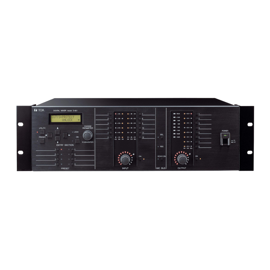
19-inch rack-mounted (3u high) digital mixer
Hide thumbs
Also See for D-901:
- Instruction manual (84 pages) ,
- Spec sheet (13 pages) ,
- Specifications (8 pages)

Related Manuals for Toa D-901


Summary of Contents for Toa D-901
- Page 1 INSTRUCTION MANUAL DIGITAL MIXER D-901 (Version 3) Thank you for purchasing TOA's Digital Mixer. Please carefully follow the instructions in this manual to ensure long, trouble-free use of your equipment.
-
Page 2: Table Of Contents
1. SAFETY PRECAUTIONS 2. GENERAL DESCRIPTION 3. FEATURES 4. HANDLING PRECAUTIONS 5. NOMENCLATURE AND FUNCTIONS 5.1. D-901 Digital Mixer Front ... 8 Rear ... 11 5.2. Optional Modules 5.2.1. D-921F Microphone/Line Input Module ... 12 5.2.2. D-921E Microphone/Line Input Module ... 12 5.2.3. - Page 3 8.6.2. Input trim polarity settings ... 28 8.7. High-Pass Filter Settings 8.7.1. Cutoff frequency settings ... 29 8.7.2. Q settings ... 29 8.8. Equalizer Settings 8.8.1. Gain settings ... 30 8.8.2. Center frequency settings ... 30 8.8.3. Q settings ... 30 8.9.
- Page 4 9.4.1. Parametric equalizer ... 47 9.4.2. High-pass filter ... 47 9.4.3. Low-pass filter ... 48 9.4.4. High shelving filter ... 48 9.4.5. Low shelving filter ... 48 9.4.6. Horn equalizer ... 49 9.4.7. Notch filter ... 49 9.4.8. All-pass filter ... 49 9.5.
- Page 5 18.2. Digital Input/Output ... 84 19. PARAMETER SETTING ITEMS AND SETTING RANGES 20. SPECIFICATIONS 20.1. D-901 Digital Mixer ... 89 20.2. D-921F Microphone/Line Input Module (Optional) ... 90 20.3. D-921E Microphone/Line Input Module (Optional) ... 90 20.4. D-922F Microphone/Line Input Module (Optional) ... 90 20.5.
-
Page 6: Safety Precautions
AC outlet and contact your nearest TOA dealer. Make no further attempt to operate the unit in this condition as this may cause fire or electric shock. -
Page 7: General Description
2. GENERAL DESCRIPTION TOA's D-901 is a 19-inch rack-mounted (3U high) digital mixer configured with 12 inputs, 8 buses, and 8 outputs. It features signal processing functions necessary for sound systems such as feedback suppression and auto-mixing. All functional parameters can be set at the unit*. Settings can be stored in the unit's internal memory as "preset memory"... -
Page 8: Nomenclature And Functions
OUTPUT (Refer to p. 10.) Lights when the power is switched ON. p. 68.) Flashes when the D-901 is communicating with a ENTER] This knob can be rotated to change parameters or select setting contents, and also operates as a push switch. - Page 9 Preset Memory Selection Section PRESET Input Channel Control Section INPUT 15. Input Channel Selector Keys [1 – 12] Used to select the input channel for sound volume adjustment or parameter setting. The Input channel indicator [SEL] (16) lights when a key is pressed, causing the corresponding channel number to be displayed on the setting screen.
- Page 10 Microphone Bus Control Section EFFECT MIC BUS 20. Microphone Bus Selector Key [SEL] Used to set the microphone bus parameters or adjust the volume. Pressing this key causes the Output Channel Control Section PEAK +12dB +6dB -6dB -12dB -20dB -40dB OUTPUT 25.
-
Page 11: Rear
[Rear] RS-232C DIGITAL MIXER SIGNAL model D-901 TOA Corporation MADE IN JAPAN Slot 9 Control module slot 31. Cooling Fan CAUTION Do not block the fan exhaust vent. Doing so may cause heat to build up inside the unit and result in fire. -
Page 12: Optional Modules
5.2. Optional Modules Notes • Make sure that the power is switched OFF before attaching or detaching modules. • To avoid failures due to static electricity, do not touch the parts or terminals on the circuit board of both the unit and module. -
Page 13: D-922F Microphone/Line Input Module
5.2.3. D-922F Microphone/Line Input Module OFF : PHANTOM NORMAL LIFT : GND LINE +4dB(LINE) -36dB(MIC) -10dB(LINE) -50dB(MIC) OFF : PHANTOM NORMAL LIFT : GND LINE +4dB(LINE) -36dB(MIC) -10dB(LINE) -50dB(MIC) ACCESSORY I.T.E 78CK 5.2.4. D-922E Microphone/Line Input Module OFF : PHANTOM NORMAL LIFT : GND LINE... -
Page 14: D-923Ae Digital Input Module
5.2.6. D-923AE Digital Input Module DIGITAL IN AES/EBU 52. AES/EBU Digital Input Terminal [AES/EBU, 1/2] (XLR-3-31 equivalent) Digital input terminal of AES/EBU format. (Pin 1: Ground; Pin 2: Signal; Pin 3: Signal) 3: Signal Use the XLR-3-12C or its equivalent for connection. -
Page 15: D-971R Line Output Module
5.2.10. D-971R Line Output Module 2(R) 1(L) 4(R) 3(L) ACCESSORY I.T.E 78CK 57. Monaural Output Terminals [1(L), 2(R), 3(L), 4(R)] Unbalanced, RCA pin jack output terminals. Each output is equipped with a 2-channel splitter. Output signal level: –10 dB 5.2.11. D-972AE Digital Output Module DIGITAL OUT AES/EBU AES/EBU... -
Page 16: D-983 Remote Control Module
5.2.14. D-983 Remote Control Module CTRL OUT CTRL IN 7-12 9-12 13-18 13-16 19-24 5.2.15. D-984VC VCA Control Module CTRL IN IN CH 7-12 CTRL OUT OUT CH 63. Contact Input Terminal [CTRL IN, 1-6, 7-12, 13-18, 19-24] Six-circuit RJ45 contact input terminals. -
Page 17: Setting Basics
6. SETTING BASICS 6.1. Setting Procedures The D-901's functions need to be set using the front-mounted keys and knob according to scenes of use. After connecting all external equipment, check the following, then follow the procedures below to set each of the unit's functions. -
Page 18: Setting Flowcharts
Settings need not be saved when temporarily setting or changing parameters. 6.2. Setting Flowcharts All the functions described hereinafter can also be set at a PC using the dedicated software. Please access our website "http://www.toa-products.com/international/" for its download. In the following charts, the Screen shift keys [ shift keys [... - Page 19 (From the previous page) Compressor/Auto-Leveler Mode Selection (Compressor mode) Compressor settings (p. 31) Threshold Level Settings Ratio settings Attack time settings Release time settings Makeup gain settings Attack Time Settings Threshold Level Settings Auto-Mixing Group Settings Priority Settings NOM Attenuation ON/OFF Settings Input Channel Gain Settings Input Channel Group Trim Gain Settings...
- Page 20 (From the previous page) Input 12 Gain Settings Output 1 Gain Settings Output 8 Gain Settings * The number of filters to be displayed differs depending on crossover configuration settings. (Refer to p. 62.) Same items as for Input 1 Output Channel Gain Settings (p.
-
Page 21: Microphone Bus Settings
6.2.2. Microphone bus settings Microphone bus selector key Dynamic Mode Settings Mode Confirmation (Filter 1 settings) Mode Confirmation (Filter 12 settings) Effect key EFFECT Echo Gain Settings Bus Assignment Settings 6.2.3. Preset memory settings Preset key PRESET Preset Memory Save Preset Memory Recall Preset Memory Delete Preset Memory Crossfade Time... -
Page 22: Utility Settings
6.2.4. Utility settings Utility key UTILITY Stereo Link Settings Group Settings Crossover Configuration Settings NOM Attenuation Settings (p. 64) Input Contact Number Selection Output Contact Number Selection Protect Settings Control Mode Selection All Input/Output Channel Gain Confirmation All Input/Output VCA Status Confirmation Individual Slots Confirmation Cooling Fan Operating Status... -
Page 23: Setting Keys And Knob
Preset memory selection section Input channel control section INPUT Input volume Input channel control selector keys Input channel ON/OFF key Parameter input section DIGITAL MIXER model D-901 UTILITY LOCK PRESET ENTRY SECTION PRESET Microphone bus control section EFFECT MIC BUS Microphone bus... -
Page 24: Setting Screen Displays
6.4. Setting Screen Displays [Input/Output Gain Setting Screen Example] Indicates the object currently being set. In this example, IN1 (Input 1) is the object being set. Pressing the switches the display to the input trim gain setting screen. The [IN 1] is displayed on the first line, and the IN 1 (Input 1) trim gain becomes the setting object. -
Page 25: Input/Output Gain Settings
7. INPUT/OUTPUT GAIN SETTINGS There are 3 possible setting methods. 7.1. Input and Output Channel Control Section Settings Step 1. Press the desired Input (or Output) channel selector key. The selected channel's SEL indicator lights. Note When Group setting is performed, selecting a channel in the group allows all SEL indicators of the input channels grouped together to light all at once. -
Page 26: Input-Related Settings
8. INPUT-RELATED SETTINGS The channel selected with the Input channel selector keys can be enabled or disabled using the Input channel ON/OFF key. To enable or disable individual functions, use the function ON/OFF key when each function is displayed. 8.1. Phantom Power ON/OFF Settings [ I N P H A N T O M O F F... -
Page 27: Channel Status Verification (Only With D-923Ae Or D-937Sp Module)
8.4. Channel Status Verification Input signal status Sampling frequency verification verification [ I N 1 ] S T A T U S [ I N 1 ] S T A T U S L O C K 4 8 k H z Using D-923AE: Input trim settings (next page) Using D-937SP: Line (stereo) input selection (next page) 8.4.1. -
Page 28: Line (Stereo) Input Selection (Only With D-936R Or D-937Sp Module)
8.5. Line (Stereo) Input Selection Using D-936R: Line input mode selection (p. 26) Using D-937SP: Channel status verification (previous page) [ I N L I N E S E L [ 1 ] 8.6. Input Trim Settings Using D-921F or D-921E: PAD (Input sensitivity) settings (p. 26) Using D-936R or D-937SP: Line (stereo) input selection (previous section) Using D-923AE: Channel status verification (previous page) Gain... -
Page 29: High-Pass Filter Settings
8.7. High-Pass Filter Settings The high-pass filter function can be enabled or disabled for the displayed channel by using the function ON/OFF key even when any of the following screens is displayed. The function ON/OFF Indicator lights when enabled (ON). [Screen display operations] Input trim settings (previous page) Cutoff frequency... -
Page 30: Equalizer Settings
8.8. Equalizer Settings When the (low or high frequency) Equalizer setting screen is displayed, equalization for the displayed channel can be enabled or disabled by pressing the function ON/OFF key. When enabled (ON), the function ON/OFF indicator lights. [Screen display operations] High-pass filter settings (previous page) Gain [ I N 1 ] P E Q - L... -
Page 31: Compressor/Auto-Leveler Mode Selection
8.9. Compressor/Auto-Leveler Mode Selection Select which function to use, compressor (next section) or auto-leveler (p. 33). Equalizer Settings (previous page) PARAMETER [ I N C O M P M O D E C O M P PUSH-ENTER Compressor settings (next section) or auto-leveler settings (p. -
Page 32: Ratio Settings
8.10.2. Ratio settings [ I N C O M P R A T I O 1 : 1 8.10.3. Attack time settings [ I N C O M P A T T A C K 1 0 . 0 m s 8.10.4. -
Page 33: Auto-Leveler Settings
8.11. Auto-Leveler Settings The auto-leveler function performs to keep the output level constant by suppressing the change of sound volume. Setting the target level (the constant level to be automatically adjusted to) and the maximum gain (the amount of gain to bring the lower level to the target level) automatically compensates for the input level. Note that setting an excessive amount of gain increases the input sensitivity, easily causing feedback. -
Page 34: Release Time Settings
8.11.4. Release time settings [ I N L E V E L E R R E L E A S E 1 . 0 0 s 8.12. Level Sense Settings The level sense refers to a parameter used to adjust the sensitivity by which the gate detects an input signal level. -
Page 35: Gate Settings
8.13. Gate Settings The gate function allows the input signal to be passed, attenuated or cut depending on its signal level. The gate allows the signal to pass when open, and attenuates or cuts the signal when closed. The gate opens when the input signal reaches a level above the Threshold plus Hysteresis parameter (half the Hysteresis) as shown in the figure at right. -
Page 36: Depth Settings
8.13.3. Depth settings [ I N G A T E D E P T H – 2 0 d B 8.13.4. Hold time settings [ I N G A T E H O L D 1 0 . 0 m s 8.13.5. -
Page 37: Auto-Mixing Group Settings
8.14. Auto-Mixing Group Settings Both the Ducker function (next page) and the NOM Attenuation function (p. 39) are Auto-Mixing Functions that automatically adjust individual input channel gains in response to input signal level. The auto-mixing functions can operate in each of the 4 groups, GROUP A through D. Although all the input channels are grouped into GROUP A by default, they can be individually assigned to the desired groups. -
Page 38: Ducker Settings
G R O U P 8.15. Ducker Settings The ducker function is one of the D-901's auto-mixing functions, and automatically adjusts individual input channel gains in response to input signal level. Refer to the previous page for the block diagram of the Auto- Mixing section. -
Page 39: Attack Time Settings
PUSH-ENTER 8.16. NOM Attenuation ON/OFF Settings The NOM Attenuation function is one of the D-901's auto-mixing functions, and automatically adjusts individual input channel gains in response to input signal level. Refer to p. 37 for the block diagram of the Auto-Mixing section. -
Page 40: Input Channel Gain Settings
8.17. Input Channel Gain Settings NOM attenuation ON/OFF settings (previous page) [ I N F A D E R – I N F d B Bus assignment settings (next page) or Input channel group trim gain settings (next section) 8.18. Input Channel Group Trim Gain Settings [ I N G R - T R I M + 0 . -
Page 41: Bus Assignment And Crosspoint Gain Settings
8.19. Bus Assignment and Crosspoint Gain Settings [Screen display operations] Input channel gain settings (previous page) or Input channel group trim gain settings (previous page) Bass assignment Crosspoint gain [ I N 1 ] A S S I G N [ I N 1 ] G A I N [ O U T 1 ] –... -
Page 42: Output Settings
9. OUTPUT SETTINGS Output channels selected with the Output channel selector keys can be enabled or disabled using the output channel ON/OFF key. Use the function ON/OFF key to enable or disable each function displayed on the LCD screen. 9.1. Output Channel Gain Settings [ O U T 1 ] F A D E R 0 . -
Page 43: Crossover Settings (Only When Crossover Function Is Enabled)
9.3. Crossover Settings (Only when Crossover function is enabled) The following screens are displayed only when the crossover function is enabled on the Utility setting screen. (Refer to p. 62 for more information.) [Screen display operations] Output channel gain settings (previous page) or Output channel group trim gain settings (previous page) -
Page 44: Cutoff Frequency Settings
9.3.2. Cutoff frequency settings (High frequency) [ O U T 1 ] X O V E R - H F F R E Q 1 . 0 0 k H z (Low frequency) [ O U T 1 ] X O V E R - L F F R E Q 1 . -
Page 45: Filter Settings
9.4. Filter Settings When any of the following screens is displayed, the filter function for the displayed channel can be enabled or disabled by pressing the function ON/OFF key. When enabled (ON), the function ON/OFF Indicator lights. [Screen display operations] Output channel gain settings (p. - Page 46 [Setting procedures (Example of setting output 1 – filter 2 as a horn equalizer)] [ O U T 1 ] T Y P E [ O U T 1 ] T Y P E [ O U T 1 ] T Y P E Step 1.
-
Page 47: Parametric Equalizer
9.4.1. Parametric equalizer CHANGE PARAMETER [ O U T 1 ] F I L T E R 1 T Y P E P E Q PUSH-ENTER [Gain settings] CHANGE PARAMETER [ O U T 1 ] F I L T E R 1 G A I N + 0 . -
Page 48: Low-Pass Filter
[Q settings] [ O U T 1 ] F I L T E R 1 1 . 0 0 0 9.4.3. Low-pass filter [ O U T 1 ] F I L T E R 1 T Y P E L P F - 6 d B 9.4.4. -
Page 49: Horn Equalizer
9.4.6. Horn equalizer CHANGE PARAMETER [ O U T 1 ] F I L T E R 1 T Y P E H O R N PUSH-ENTER [Gain settings] CHANGE PARAMETER [ O U T 1 ] F I L T E R 1 G A I N + 0 . -
Page 50: Compressor Settings
[Center frequency settings] [ O U T 1 ] F I L T E R 1 F R E Q 1 . 0 0 k H z [Q settings] [ O U T 1 ] F I L T E R 1 0 . -
Page 51: Attack Time Settings
9.5.3. Attack time settings PARAMETER [ O U T 1 ] C O M P A T T A C K 1 0 . 0 m s PUSH-ENTER 9.5.4. Release time settings PARAMETER [ O U T 1 ] C O M P R E L E A S E 5 0 0 m s PUSH-ENTER... -
Page 52: Microphone Bus Settings
10. MICROPHONE BUS SETTINGS The Microphone Bus setting screen is displayed when the Microphone Bus selector key is pressed. 10.1. Feedback Suppression Settings [Suppressing acoustic feedback with a simple operation] Step 1. Set the volume controls of connected external equipment to the state in which they will actually be used. -
Page 53: Auto Mode Activation
10.1.2. Auto mode activation CHANGE PARAMETER [ M i c B ] F B S A U T O S T A R T O K ? PUSH-ENTER 10.1.3. Filter number settings CHANGE PARAMETER [ M i c B ] F B S A U T O : D Y N 7 : 5... -
Page 54: Feedback Suppression Filter Setting Confirmation
10.2. Feedback Suppression Filter Setting Confirmation The settings of all 12 Dynamic and Auto mode feedback suppression filters can be quickly confirmed. [Screen display operations] Feedback suppression settings (p. 52) Frequency Filter 1 mode confirmation confirmation [ M i c B ] F I L T E R 1 [ M i c B ] F I L T E R 1 F R E Q T Y P E... -
Page 55: Effect (Echo) Settings
10.3. Effect (Echo) Settings The D-901 has an echo function, a part of an effect function. • The Effect (echo) setting screen can be displayed by pressing the Effect key, or by using the EFFECT Screen shift keys on the Microphone Bus setting screen. -
Page 56: Initial Echo (Pre-) Delay Settings
10.3.4. Initial echo (pre-) delay settings [ M i c B ] E C H O P r e D L Y 8 0 m s 10.3.5. Low-pass filter frequency settings [ M i c B ] E C H O L P F - F 3 . -
Page 57: Preset Memory Settings
11. PRESET MEMORY SETTINGS The preset setting screen is displayed when the Preset key is pressed. PRESET Pressing the key again exits the preset setting screen in any of the following settings, displaying the Input/Output Gain Setting screen. 11.1. Preset Memory Save Set parameters can be stored in memory (number of memories: 16). -
Page 58: Preset Memory Recall
11.2. Preset Memory Recall Recall the stored preset memory. Preset memory save (previous page) [ P R E S E T ] L O A D N o . O K ? 11.3. Preset Memory Delete Delete the stored preset memory. [ P R E S E T ] D E L E T E N o . -
Page 59: Preset Memory Crossfade Time Settings
11.4. Preset Memory Crossfade Time Settings Set the crossfade time when the currently selected preset memory is switched over to a newly recalled one by pressing the preset memory number. [Parameters to be cross-faded] Input/output channel gains, channel ON/OFF, bus assignment, cross-point gains. Parameters other than those above instantaneously switch when the preset memory is recalled. -
Page 60: Initial Preset Memory Selection
11.5. Initial Preset Memory Selection Select the preset memory number (1 – 16) or LAST MEMORY to be automatically recalled when the power is switched on. Preset memory crossfade time settings (previous page) LAST MEMORY Preset memory selection number 1 selection [ P R E S E T ] S T A R T [ P R E S E T ] S T A R T L A S T M E MO R Y... -
Page 61: Utility Settings
12. UTILITY SETTINGS The utility setting screen is displayed when the Utility key is pressed. UTILITY 12.1. Stereo Link Settings [ U T Y ] S T R L I N K [ I N [ I N 12.2. Group Settings By grouping multiple channels together, the gains of these channels can be simultaneously adjusted using... -
Page 62: Crossover Configuration Settings
Step 3. Rotate the Setting knob to select the channels to be grouped together with the channels displayed in the [ ] area on the upper row. (The selected channels are displayed in the " Step 4. Press the function ON/OFF key to confirm the selected channels. All of the channels set for grouping are displayed on the upper row at the right. - Page 63 Crossover configuration (high frequency) settings (previous page) (Low frequency) [ U T Y ] X O V E R – L F [ O U T 1 ] N O N E CHANGE PARAMETER PUSH-ENTER [ U T Y ] X O V E R –...
-
Page 64: Nom Attenuation Settings
12.4. NOM Attenuation Settings NOM is an acronym of Number of Open Microphones, and represents the number of microphones in open status (the number of input channels with open gates). The NOM attenuation function automatically adjusts the open microphone's input channel gain depending on the number of open microphones. -
Page 65: Contact Input/Output Settings
12.5. Contact Input/Output Settings Many different functions assigned to the input and output contacts of the D-981 or D-983 Remote Control Module, or the D-984VC VCA Control Module can be remotely controlled by connected external equipment. Use the Setting knob to select the functions to be assigned. Notes •... - Page 66 [Setting Procedures (Example. Assigning Preset Memory 3 recall to Contact Input 2)] [ U T Y ] 1 : N O N E CHANGE PARAMETER PUSH-ENTER [ U T Y ] 2 : N O N E Step 1. Rotate the Setting knob to select the input contact number. Step 2.
-
Page 67: Function Assignment To The Output Contact
12.5.2. Function assignment to the output contact The following functions can be assigned to output contacts (1 – 8 when the D-981 or D984-VC is used, and 1 – 16 when the D-983 is used). Preset memory recall tally, Channel ON/OFF tally, Contact input status tally, and Line (stereo) input selection tally The procedures for assigning functions are the same as those used when assigning functions to the input contacts. -
Page 68: Protect Settings
Individual Function Key Protect setting screen (Refer to the next page.) unlocked. Enables the Protect function, and validates the Protect function settings. CURSOR CHG PARAM * DIGITAL MIXER model D-901 CHANGE UTILITY PARAMETER LOCK PRESET PUSH-ENTER ENTRY SECTION... - Page 69 • Rotate the Setting knob to select the key(s) to be protected. • The Protect function can be enabled or disabled for the selected key(s) by pressing the function ON/OFF key. [ U T Y ] P R O T E C T A L L : O N CHANGE...
-
Page 70: Rs-232C Port Settings
International site, see below). Tips • While the D-901 is communicating with a PC, the front-mounted system lock indicator flashes. • In the above status, attempting to change settings with the front-mounted knobs or keys notifies the operator of prohibited operation by way of the indication shown below. -
Page 71: All Input/Output Channel Gain Confirmation
12.8. All Input/Output Channel Gain Confirmation RS-232C port settings (previous page) [ U T Y ] A L L F A D E R P O S I T I O N 12.9. All Input/Output VCA Status Confirmation All input/output channel gain confirmation (previous section) [ U T Y ] A L L V C A... -
Page 72: Module Type Confirmation
12.10. Module Type Confirmation Types of modules installed in the unit's rear slots can be confirmed. [Screen display operations] All input/output channel gain confirmation (previous section) Individual slots confirmation All slots confirmation [ U T Y ] S L O T S L O T : 1 2 3 4 5 6 7 8 9 1 : D - 9 2 1 F / E ( A ) T Y P E : A A B B C –... -
Page 73: All Slots Confirmation
The fan is detected as having failed when it stops or if its rotation speed is extremely slow. In such cases contact your TOA dealer. • If the fan rotation speed decreases dramatically, the display switches over to the cooling fan failure screen even when another screen is displayed. -
Page 74: Restoring Factory Default Settings
The software version number can be confirmed at the xxx indication. For example when the PC Software version is 3.00 and Firmware version is 3.01, it is indicated as "D901PCv300e_f301.exe. Step 1. Connect both RS-232C ports of the D-901 and the PC using a 9-pin straight cable (male-to-female cord). - Page 75 Step 4. Click the Comm Settings button. The Comm Settings screen appears. Step 5. Set the PC's Com port the D-901 is connected to, and the Speed (baud rate*) equal to the D-901's RS-232C transmission rate. Click OK, then the Comm Settings screen closes.
-
Page 76: Rack Mounting
After confirming all the above items, follow the procedure from Sep 3 again. If the same "No Replay" indication still appears in this Step 6, turn the D-901's power off, and on again. Then, follow the steps again from the beginning. -
Page 77: Connections
D-901 INPUT RS-232C ACOUS AC100V 50/60Hz 45W OUTPUT DIGITAL MIXER SIGNAL model D-901 TOA Corporation MADE IN JAPAN ACCESSORY I.T.E 78CK Remote controller BGM player (Cassette deck, CD player, MD player, etc.) ACCESSORY I.T.E 78CK ACCESSORY I.T.E 78CK ACCESSORY I.T.E 78CK... -
Page 78: Connection Example 2 (Broadcasting To Two Separate Zones)
16.2. Connection Example 2 (Broadcasting to two separate zones) D-901 RS-232C ACOUS AC100V 50/60Hz 45W DIGITAL MIXER SIGNAL model D-901 TOA Corporation MADE IN JAPAN Remote controller Main speaker (R) Main speaker (L) BGM player (Cassette deck, CD player, MD player, etc.) -
Page 79: Removable Terminal Plug Connection
16.3. Removable Terminal Plug Connection Cautions • Be sure to use shielded cables for audio signal lines. • Avoid soldering stranded or shielded cable, as contact resistance may increase when the cable is tightened and the solder is crushed, possibly resulting in an excessive rise in joint temperatures. Cable end treatment Solid or stranded cable Connector connections... -
Page 80: Connections Of The D-984Vc
• Use 10 kΩ potentiometers of taper B. • Up to 6 volume controls can be connected to each V pin. [Connections to the input channel VCA terminal] D-901's volume Minimum level +5 V [Input channel VCA terminals] IN CH Pin No. -
Page 81: Contact Controls
[Connections to the output channel VCA terminal] D-901's volume Minimum level +5 V 16.5.3. Contact controls (5) – (8) • Preset memory recall function is assigned to the contact input and output pins at the factory. To change this function assignment to give channel ON/OFF or line input selection, refer to p. 69. -
Page 82: Block Diagram
17. BLOCK DIAGRAM Microphone/Line Input Module (D-921F or D-921E) +15 V +15 V Microphone/Line Input Module (D-922F or D-922E) +15 V DIP SW +15 V DIP SW Stereo Input Module (D-936R) Digital Input Module (D-923AE) DE-EMP DE-EMP Automatic Digital Input Module (D-937SP) OPTICAL DE-EMP... - Page 83 Only when using the D-984VC 1 2 3 4 5 6 7 8 M GR Trim Fader Fader GR Trim GR Trim Fader GR Trim Fader GR Trim Fader GR Trim Fader GR Trim Fader GR Trim Fader Effect Line Output Module (D-971M or D-971E) SIG LED Filter(6) COMP Delay...
-
Page 84: Level Diagrams
18. LEVEL DIAGRAMS 18.1. Analog Input/Output Microphone/Line Input Module D-921F, D-921E, D-922F, or D-922E Max. Input (+24) LINE (+4) LINE (-10) (-36) (-50) 18.2. Digital Input/Output Digital Input Module D-923AE or D-937SP dBFS Max. Input (0 dBFS) Digital Clipping Level (+20 dB) Peak LED Turns ON (+17 dB) (0 dB) -
Page 85: Parameter Setting Items And Setting Ranges
19. PARAMETER SETTING ITEMS AND SETTING RANGES Note: Underlined parameters are factory-preset. [Input and Output/Trim Settings] Setting Item Input Channel Gain Input Trim Gain Input Trim Polarity Input Channel Group Trim Gain Output Channel Gain Output Channel Group Trim Gain [D-921F or D921E settings (enabled when the module is mounted)] Setting Item Phantom Power... - Page 86 [Auto-Leveler Settings] Setting Item Target Level Maximum Gain Attack Time Release Time [Level Sense Settings] Setting Item Attack Time Release Time [Gate Settings] Setting Item Threshold Level Hysteresis Depth Hold Time Attack Time Release Time ON/OFF [Auto-Mixing Group Settings] Setting Item Auto-Mixing Group [Ducker Settings] Setting Item...
- Page 87 [Bus Assignment and Crosspoint Gain Settings] Setting Item Input 1 Input 2 – 12 Microphone Bus Gain [Crossover Settings] Setting Item 20 Hz – 20 kHz (1 kHz), 1/24 octave steps Cutoff Frequency Slope Through, 6 dB/oct, 12 dB/oct BS, BS: Bessel 12 dB/oct BW, 12 dB/oct LR, 18 dB/oct BS, BW: Butterworth...
- Page 88 [Feedback Suppression Settings] Parameter DYNAMIC Dynamic mode ON/OFF AUTO START Auto mode activation AUTO : DYNAMIC Number of the filters used in each mode CLEAR DYNAMIC Reset the filters set for Dynamic mode CLEAR AUTO Reset the filters set for Auto mode [Feedback Suppression Filter Setting] Setting Item Gain...
-
Page 89: Specifications
20. SPECIFICATIONS 20.1. D-901 Digital Mixer Power Source 100 – 120 V, 230 V AC, 50/60 Hz Power Consumption 40 W Frequency Response 20 – 20,000 Hz, ±1 dB (±4 dB* input) Input Max. 12 channels, modular construction (modules optional) Output Max. -
Page 90: D-921F Microphone/Line Input Module (Optional)
20.2. D-921F Microphone/Line Input Module (Optional) Input A/D Converter Sampling Frequency Frequency Response Dynamic Range Total Harmonic Distortion Finish Dimensions Weight 20.3. D-921E Microphone/Line Input Module (Optional) Input A/D Converter Sampling Frequency Frequency Response Dynamic Range Total Harmonic Distortion Finish Dimensions Weight •... -
Page 91: D-922E Microphone/Line Input Module (Optional)
20.5. D-922E Microphone/Line Input Module (Optional) Input 2 channels, –50/–36/–10/+4 dB* (Selectable with the DIP switch), 4.7 kΩ, electronically-balanced, 3-pin removable terminal block Phantom power supply (+15 V, can be set with the DIP switch) Ground lift switch (can be set with the DIP switch) A/D Converter 20 bits Sampling Frequency... -
Page 92: D-971M Line Output Module (Optional)
20.9. D-971M Line Output Module (Optional) Output D/A Converter Sampling Frequency Frequency Response Dynamic Range Total Harmonic Distortion Finish Dimensions Weight 20.10. D-971E Line Output Module (Optional) Output D/A Converter Sampling Frequency Frequency Response Dynamic Range Total Harmonic Distortion Finish Dimensions Weight •... -
Page 93: D-961Sp Digital Output Module (Optional)
20.13. D-961SP Digital Output Module (Optional) Output Stereo 2 channels (with splitter, each pair of optical output and coaxial output in parallel), 0.5 V (p-p), 75 Ω, Coaxial RCA jack x 2 Square optical connector x 2 Applicable Format S/PDIF (2 channel multiplexed) Sampling Frequency 48 kHz Finish... -
Page 94: D-983 Remote Control Module (Optional)
20.15. D-983 Remote Control Module (Optional) Contact Input COM + Terminals 1 – 24: Open voltage 5 V DC, short-circuit current 5 mA, Preset Memory Any preset memory can be recalled. Selection Control method: No-voltage make of over 100 ms or Volume Control Any input/output channel volume can be turned UP or DOWN.
Need help?
Do you have a question about the D-901 and is the answer not in the manual?
Questions and answers