Table of Contents
Advertisement
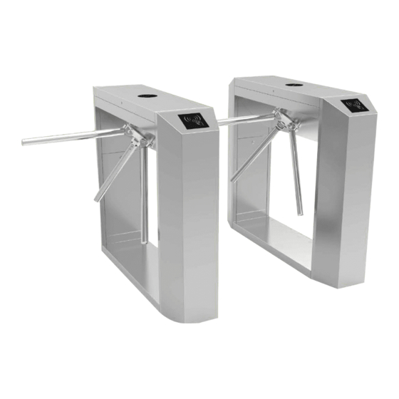
TS200 Series Tripod Turnstile
Thank you for choosing our product. Please read the instructions
carefully before operation. Follow these instructions to ensure that the
product is functioning properly. The images shown in this manual are
for illustrative purposes only.
P a g e
| 1
Copyright©2020 ZKTECO CO., LTD. All rights reserved.
User Manual
Advertisement
Table of Contents

Subscribe to Our Youtube Channel
Related Manuals for ZKTeco TS200 Series


Summary of Contents for ZKTeco TS200 Series
- Page 1 Thank you for choosing our product. Please read the instructions carefully before operation. Follow these instructions to ensure that the product is functioning properly. The images shown in this manual are for illustrative purposes only. P a g e Copyright©2020 ZKTECO CO., LTD. All rights reserved.
- Page 2 TS200 Series Tripod Turnstile User Manual About the Manual This manual introduces the operations of TS200 Series Tripod Turnstile product. All figures displayed are for illustration purposes only. Figures in this manual may not be exactly consistent with the actual products.
- Page 3 TS200 Series Tripod Turnstile User Manual Document Conventions Conventions used in this manual are listed below: GUI Conventions For Software Convention Description Bold font Used to identify software interface names e.g. OK, Confirm, Cancel Multi-level menus are separated by these brackets. For example, File > Create >...
-
Page 4: Table Of Contents
TS200 Series Tripod Turnstile User Manual Table of Contents TECHNICAL SPECIFICATIONS ........................ 4 UNPACKING AND TESTING THE TRIPOD TURNSTILE ..............5 ..............................5 NSTALLATION ........................5 OWER EST BEFORE NSTALLATION EQUIPMENT INSTALLATION ......................... 6 ............................6 NSTALLATION ONDITIONS ..................................7 ABLING ................................ -
Page 5: Technical Specifications
TS200 Series Tripod Turnstile User Manual Please read this document carefully before installation and using the device. Technical Specifications AC 100~120V Input Voltage /200~240V, Arm Length (mm) 50Hz /60Hz Indoor and Operating Environment Outdoor Dimension(mm) (Figure 1) L = 1200, W = 280, H = 980... -
Page 6: Unpacking And Testing The Tripod Turnstile
TS200 Series Tripod Turnstile User Manual Unpacking and Testing the Tripod Turnstile Arm Installation In order to prevent the arm from damaging during transportation, the arm will not be initially installed to the devices. Installation procedure Put the arm kit into the hole of cabinet; make sure the screw holes match with mechanism core, then tighten 3 hex screws, as shown in Figure 2-1. -
Page 7: Equipment Installation
TS200 Series Tripod Turnstile User Manual Figure 2-2 Equipment Installation Installation Conditions The equipment must be installed on concrete ground, ensuring that expansion bolts can be secured firmly. You are suggested to install an assistant framework or fence to form a passageway, as shown in Figure 3-1. -
Page 8: Cabling
TS200 Series Tripod Turnstile User Manual Figure 3-2 Cabling There are inlets in the bottom plate for cabling, as shown in Figure 3-3. Units of all data is millimeter. Power supply and communication wire should go through the inlet. Cable protection covers are suggested to use if it is surface mounted. -
Page 9: Installation
TS200 Series Tripod Turnstile User Manual Installation 1. Drill holes. Drill holes according to the locations of holes as shown in Figure 3-3. 2. Fix the mounting plate to its original position. Place the mounting plate properly, then apply screw securing glue on the surface and threads of the expansion bolts, install four expansion bolts to secure the mounting plate, and use a horizontal ruler to test the levelness of the mounting plate. -
Page 10: Cable Diagram
TS200 Series Tripod Turnstile User Manual Cable Diagram Function Description of the Turnstile Control Board If you are using standard device that without RFID or Fingerprint reader, you need to connect access control system to the main board, please check the content in this chapter carefully. -
Page 11: Connection Diagram Of The Access Controller
TS200 Series Tripod Turnstile User Manual Note: The third party access control system lock relay trigger time should be 1 second or less than 1 second. Connection Diagram of the Access Controller Figure 4-2 Note: The lock relay duration of access controller device needs to be set to 1s. Forbidden using electrically charged objects to connect to the port of Opening Signal Input, otherwise will damage the control board. -
Page 12: Direction Indicator
TS200 Series Tripod Turnstile User Manual Bit Setting Duration Bit Setting Duration Note: The turnstile’s opening duration is set to 5s by default. 4.3.2Direction Indicator It is to indicate whether people can pass through the gate. The green arrow means passing is allowed while the red cross "X"... -
Page 13: Equipment Precautions And Maintenance
TS200 Series Tripod Turnstile User Manual 0 = disabled Note: Please set to 0 when working normally, that is to say that Alarm Function is disabled. Equipment Precautions and Maintenance Precautions It is recommended to purchase additional accessories to use the product outdoors. -
Page 14: Maintenance
TS200 Series Tripod Turnstile User Manual This equipment is designed to drop the arms automatically if there is power failure thus people can pass freely. Also, there is an interface on the turnstile control board connecting with an emergency switch (J6 Drop Arm) which keeps the tripod turnstile open in case of emergencies. Please lift the arms manually after at least 6 seconds after power restoration. -
Page 15: Troubleshooting
TS200 Series Tripod Turnstile User Manual Troubleshooting Symptom Troubleshooting It may be caused by the power supply or circuit. The indicator is not lit when the Check whether the connection cable and power cable are equipment is powered on. damaged, or whether the wiring is loosed. -
Page 16: Attachment 1 Factory Settings
TS200 Series Tripod Turnstile User Manual Attachment 1 Factory Settings Function Default Lock Driving Duration Door Sensor None Verification Interval Controller TCP/IP: 192.168.1.201 Communication Turnstile Opening Duration Passing Direction Passing is allowed in both Indicator directions Continue Passing Disabled Function... -
Page 17: Attachment 2 Connection Diagram Of Control Board And Access Control Panel
TS200 Series Tripod Turnstile User Manual Attachment 2 Connection Diagram of Control Board and Access Control Panel Warning: This is a class A product. In a domestic environment, this product may cause radio interference so that the user may have to take adequate additional measures.
Need help?
Do you have a question about the TS200 Series and is the answer not in the manual?
Questions and answers
Куда подключить кнопку выход управления турникетом для открывания турникета охраником
Connect the exit button to the Opening Signal Input port on the turnstile control board. Ensure the connected device is not electrically charged to avoid damaging the control board.
This answer is automatically generated