Advertisement
Table of Contents
IPA T RLY4 • Setup Guide
This guide provides instructions for an experienced installer to install the Extron IPA T RLY4 relay accessory and to make all
connections.
The IPA T RLY4 is an IPLink
relay is de-energized) (NO) and normally closed (NC) contacts.
The relay accessory converts a solid state (up to 12 VDC) signal, from a Flex I/O port or Digital I/O port on an Extron control
processor, to a relay contact closure. The relay contacts can handle up to 24 VAC or 24 VDC as a tally signal, contact closure
signal, or control signal to drive devices in your system, such as a lighting system (see figure 1) or remote screens. The relay
contacts are protected by an overvoltage circuit.
The compact IPA T RLY4 can be concealed out of the way anywhere in your system with the included hook and loop fastener strip.
Extron
12 V Power
Supply
Figure 1.
Typical IPA T RLY 4 Application
Connections
NOTE:
The 5-pole captive screw input connector and four 3-pole captive screw output connectors are included with the
unit, but you must supply the cable. Extron recommends the CTL Series cable, available non-plenum and plenum bulk
rolls and plenum pre-cut lengths.
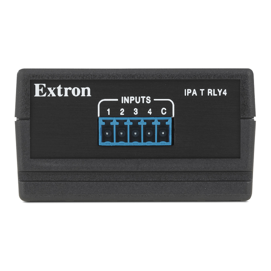
A A
INPUTS
IPA T RLY4
1
2 3 4
Figure 2.
IPA T RLY4
Input Connections
Inputs — Connect the 12 VDC source to the common voltage (C) terminal of the 5-pole captive screw
A
connector. Connect the appropriate terminal (1 though 4) to the digital output or flex I/O of the Extron control
processor.
Accessory product. The relay accessory consists of four output relays with normally open (when the
®
Extron
IPCP Pro 255Q xi
Ethernet Control
Processor
N
L A
/ O
L I
T A
G I
A V
D I
N
L A
2
IP A
G
M
/ S
C O
4
T R
I R
3
L Y
4
2
1
1
U S
IN
M
1
P U
C O
G
e B
R x
2
T S
T x
G
3
-S
4
Y S
+ S
G
C
S
C T
L A
+ V
S
R T S
R E
G
C
6 W
R x
T =
2
T x
O U
1
L
R
V O
P W
G
C
V
W E
R
P O
1 2 V
X
M A
A
1 .0
Front
+12 VDC
(Common)
RELAY 1
C
NO C NC
B B
Connections
Y 4
L A
R E
Y 3
L A
R E
N C
Y 2
L A
C
N O
R E
Y 1
N C
L A
C
N O
R E
N C
C
N O
N C
C
N O
Rear
Extron
IPA T RLY4
Relay Accessory
Lighting System
RELAY 4
RELAY 2
RELAY 3
NO C NC
NO C NC
NO C NC
B B
B B
B B
1
Advertisement
Table of Contents

Related Manuals for Extron electronics IPA T RLY4


Summary of Contents for Extron electronics IPA T RLY4
- Page 1 (see figure 1) or remote screens. The relay contacts are protected by an overvoltage circuit. The compact IPA T RLY4 can be concealed out of the way anywhere in your system with the included hook and loop fastener strip. Extron...
- Page 2 • Figure 3 is a wiring diagram of a typical application: an Extron MLC 104 IP Plus controlling an IPA T RLY4 relay function (see the MLC 104 Plus Series User Guide for information on configuring the MLC to control the IPA T RLY4).
- Page 3 Operation When an input signal is applied to one of the input terminals of the IPA T RLY4, the signal toggles the state of that IPA T RLY4 output relay; the relay NO contacts close, routing the signal for the connected device, and its NC contacts open, interrupting the signal for the connected device.
- Page 4 For information on safety guidelines, regulatory compliances, EMI/EMF compatibility, accessibility, and related topics, see the Extron Safety and Regulatory Compliance Guide on the Extron website. www.extron.com © 2003-2022 Extron — All rights reserved. 68-739-03 Rev. E All trademarks mentioned are the property of their respective owners. 10 22 Worldwide Headquarters: Extron USA West, 1025 E.
Need help?
Do you have a question about the IPA T RLY4 and is the answer not in the manual?
Questions and answers