Advertisement
Available languages
Available languages
Quick Links
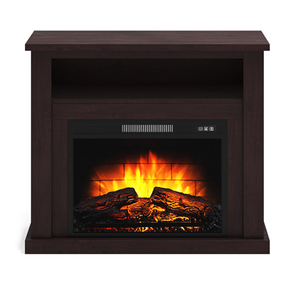
Media Fireplace Console
Stock # MSD036158813001
If you have any questions regarding assembly or if parts are missing, DO NOT return this item to the
store where it was purchased. Please call our customer service number and have your instructions
and parts list ready to provide the model name, part name or factory number:
Pacific Standard Time: 8:30 a.m. - 4:30 p.m., Monday - Friday
Or visit our web site 24 hours a day, 7 days a week for product assistance at
THIS INSTRUCTION BOOKLET CONTAINS IMPORTANT SAFETY INFORMATION.
PLEASE READ AND KEEP FOR FUTURE REFERENCE.
# MSD036158813002
ADULT ASSEMBLY REQUIRED
www.whalenstyle.com
Or e-mail your request to parts@whalenfurniture.com
Date 2020-07-16
866-942-5362
Rev. 0001-A
LOT NUMBER:
DATE PURCHASED:
Black Finish
Dark Cherry Finish
/
/
Advertisement

Subscribe to Our Youtube Channel
Related Manuals for Whalen Mainstays MSD036158813001


Summary of Contents for Whalen Mainstays MSD036158813001
- Page 1 LOT NUMBER: DATE PURCHASED: Media Fireplace Console Stock # MSD036158813001 Black Finish # MSD036158813002 Dark Cherry Finish ADULT ASSEMBLY REQUIRED If you have any questions regarding assembly or if parts are missing, DO NOT return this item to the store where it was purchased. Please call our customer service number and have your instructions and parts list ready to provide the model name, part name or factory number: 866-942-5362 Pacific Standard Time: 8:30 a.m.
- Page 2 M A X I M U M R E C O M M E N D E D W E I G H T L O A D S MANUFACTURER: Whalen Furniture Manufacturing CATALOG: Media Fireplace Console MODEL # MSD036158813001 / MSD036158813002 FITS UP TO MOST 42”...
- Page 3 IMPORTANT Before you begin: Open, identify and count all parts prior to assembly. Lay out parts on a flat and non- abrasive surface. You will need the parts identified on page 4 and 5 of this instruction manual. NOTE: IT IS VERY IMPORTANT TO USE GLUE WITH DOWELS. EXCESS GLUE CAN BE WIPED OFF WITH DAMP CLOTH.
- Page 4 Parts and Hardware List Please read completely through the instructions and verify that all listed parts and hardware are present before beginning assembly. A- Top Panel (Qty. 1) B- Media Shelf (Qty.1) C- Base (Qty. 1) D- Left Side Panel (Qty. 1) E- Right Side Panel (Qty.
- Page 5 Parts and Hardware List Please read completely through the instructions and verify that all listed parts and hardware are present before beginning assembly. (1) Cam Lock (2) Cam Bolt (3) M8 x 30 mm Wood Dowel (Qty. 23+1 extra) (Qty. 23+1 extra) (Qty.
- Page 6 Assembly Instructions ② x 13 1. Unpack the unit and confirm that you have all the hardware and required parts. Assemble the unit on a carpeted floor or the empty carton to avoid any scratch. 2. Securely screw the Cam Bolts (2) into the designated small holes on the Top Panel (A), Media Shelf (B) and Base (C) with a Phillips screwdriver.
- Page 7 Assembly Instructions ② x 10 3. Continue to screw the Cam Bolts (2) into the designated small holes on the Side Panels (D and E) and Front Moldings (F and G).
- Page 8 Assembly Instructions ③ x 8 4. Insert the 30 mm Wood Dowels (3) into the inner holes on the Media Shelf (B), Upper Front Molding (H) and Center Crossbar (I). Make sure that you use a small amount of glue with both ends of all dowels.
- Page 9 Assembly Instructions ⑦ x 3 5. Align and attach the Upper Front Molding (H) to the front of Top Panel (A) with three 40 mm Screws (7).
- Page 10 Assembly Instructions ① x 3 6. Align and attach the Center Crossbar (I) to the Media Shelf (B) by engaging three Cam Locks (1) (Refer to page 3 on Cam Lock system operation supplement).
- Page 11 Assembly Instructions ③ x 14 7. Insert the 30 mm Wood Dowels (3) into the inner holes on the Side Panels (D and E) and Front Moldings (F and G). Make sure that you use a small amount of glue with both ends of all dowels.
- Page 12 Assembly Instructions ① x 6 8. Align and attach the Left Front Molding (F) to the Left Side Panel (D) by engaging three Cam Locks (1). 9. Repeat the same procedure to attach the Right Front Molding (G) to the Right Side Panel (E).
- Page 13 Assembly Instructions ① x 4 10. Align and attach the Media Shelf (B) between the Side Panels (D and E) by engaging four Cam Locks (1).
- Page 14 Assembly Instructions ⑦ x 2 ① x 4 11. Using the wood dowels as a guide, firmly press the previous assembly to the Base (C) and fasten them into place by engaging four Cam Locks (1). 12. Proceed to thread two 40 mm Screws (7) through the Base (C) and securely screw into the Front Moldings (F and G).
- Page 15 Assembly Instructions ① x 6 13. Place the Top Panel (A) onto the inserted wood dowels on the vertical panels (D, E, F and G) and fasten it in place by engaging six Cam Locks (1).
- Page 16 Assembly Instructions ⑥ x 4 14. Ask for assistance to flip the unit around at its front edge as shown. 15. Fasten the Center Crossbar (I) to the Front Moldings (F and G) with four 28 mm Screws (6).
- Page 17 Assembly Instructions ⑧ x 2 ④ x 4 16. With the pilot holes as a guide, fasten the Center Crossbar (I) to the stiles on Front Moldings (F and G) by attaching two Mending Plates (8) at the joints, using two 12 mm Screws (4) per plate.
- Page 18 Assembly Instructions ⑤ x 12 17. Now, go back and securely tighten all the Cam Locks and the Screws. Make sure that all the parts are tight and there are no gaps between the parts. This will help keep the unit square. 18.
- Page 19 Assembly Instructions ⑨ x 6 19. Ask for assistance to stand the unit upright. 20. Plug the Cam Lock Covers (9) onto the visible Cams Locks to conceal the Cams.
- Page 20 Assembly Instructions 21. Unpack the fireplace insert from the inner box and follow the instructions to install the Top Trim and Side Trims to the fireplace insert. 22. Lift the fireplace insert carefully into the back of the assembled mantel and center it in the opening. drag the insert across the Base (C) as it may scratch the unit.
- Page 21 Assembly Instructions NOTE: To prevent your TV from tipping, you must install the Strip Stopper if you place your flat panel television directly on the console. Otherwise, skip to step 24. 23. Remove the paper backing from the Stop Rail (K), then properly align the Stop Rail with the top edge of the stopper template on Top Panel (A).
- Page 22 Assembly Instructions Tools required (not provided): Phillips screwdriver, stud finder, tape measure, pencil, power drill and 1/8’’ drill bit. 25. Ask for assistance to position the assembled fireplace at the desired location against a wall. If necessary, adjust the pre-attached floor levelers at the bottom of the Base (C) to level the unit. 26.
-
Page 23: Care And Maintenance
Should this product be defective in workmanship or materials or fail under normal use, we will repair or replace it for up to one (1) year from date of purchase. Every Whalen Furniture product is designed to meet your highest expectations. We guarantee that you will immediately see the value of our fine furniture. - Page 25 LOTE NÚMERO: FECHA DE COMPRA: Consola para medios con chimenea Modelo # MSD036158813001 Acabado Negro # MSD036158813002 Acabado Cereza oscuro ENSAMBLE REQUERIDO POR ADULTO Si tienen alguna pregunta acerca del ensamble o si alguna parte está faltante, no retorne esté producto a la tienda donde lo compro.
- Page 26 M Á X I M O P E S O R E C O M E N D A D O FABRICANTE: Whalen Furniture Manufacturing CATALOGO : Consola para medios con chimenea MODELO # MSD036158813001 / MSD036158813002 PARA MAYORÍA DE LAS TELEVISIONES DE PANTALLA PLANA DE 42”...
- Page 27 IMPORTANTE Antes de comenzar: Abra, identifique y cuente todas las partes antes del ensamble. Coloque las piezas sobre una superficie plana y no abrasiva. Tendrá que las partes identificadas en la página 4 y 5 de este manual de instrucciones. NOTA: ES MUY IMPORTANTE PARA EL USO DE PEGAMENTO CON LOS PERNSO DE MADERA.
- Page 28 Lista de partes y material de ferretería Por favor lea completamente las instrucciones y verifique que estén todas las partes antes de iniciar el ensamblado. A- Panel superior (Cant. 1) B- Repisa media (Cant.1) C- Base (Cant. 1) D- Panel izquierdo (Cant. 1) E- Panel derecho (Cant.
- Page 29 Lista de partes y material de ferretería Por favor lea completamente las instrucciones y verifique que estén todas las partes antes de iniciar el ensamblado. (1) Tuerca de fijación (2) Perno de fijación (3) Clavija de madera de M8 x 30 mm (Cant.
-
Page 30: Instrucciones De Ensamble
Instrucciones de ensamble ② x 13 1. Desempacar la unidad y confirmar que se tiene todo el material de ferretería y partes requeridas. Ensamblar la unidad en un piso alfombrado o en el cartón vacío para evitar rasguños. 2. Atornillar los pernos de fijación (2) en los agujeros pequeños designados en el panel superior (A), en la repisa media (B) y en la base (C) con el desarmador estrella. - Page 31 Instrucciones de ensamble ② x 10 3. Atornillar los pernos de fijación (2) en los agujeros pequeños designados en los paneles laterales (D y E) y en las molduras frontales (F y G).
- Page 32 Instrucciones de ensamble ③ x 8 4. Insertar las clavijas de madera de 30 mm (3) en los agujeros internos en la repisa media (B), en la moldura superior frontal (H) y en el soporte central (I). Usar una cantidad pequeña de pegamento en ambos lados de las clavijas.
- Page 33 Instrucciones de ensamble ⑦ x 3 5. Alinear y adjuntar la moldura superior frontal (H) al frente del panel superior (A) con 3 pernos de 40 mm (7).
- Page 34 Instrucciones de ensamble ① x 3 6. Alinear y adjuntar el soporte central (I) a la repisa media (B) empleando 3 tuercas de fijación (1) (Consulte la página 3 del sistema de tuerca de fijación).
- Page 35 Instrucciones de ensamble ③ x 14 7. Insertar las clavijas de madera de 30 mm (3) en los agujeros internos de los paneles laterales (D y E) y de las molduras frontales (F y G). Usar una cantidad pequeña de pegamento en ambos lados de las clavijas.
- Page 36 Instrucciones de ensamble ① x 6 8. Alinear y adjuntar la moldura izquierda frontal (F) al panel izquierdo (D) empleando 3 tuercas de fijación (1). 9. Repetir el mismo procedimiento para adjuntar la moldura derecha frontal (G) al panel derecho (E).
- Page 37 Instrucciones de ensamble ① x 4 10. Alinear y adjuntar la repisa media (B) entre los paneles laterales (D y E) empleando 4 tuercas de fijación (1).
- Page 38 Instrucciones de ensamble ⑦ x 2 ① x 4 11. Usando las clavijas de madera como guía, presionar el ensable previo a la base (C) y sujetar en su lugar empleando 4 tuercas de fijación (1). 12. Proceder a ensartar 2 pernos de 40 mm (7) a traves de la base (C) y atornillar en la molduras frontales (F y...
- Page 39 Instrucciones de ensamble ① x 6 13. Poner el panel superior (A) en las clavijas de madera insertadas en los paneles verticales (D, E, F y G) y sujetar en su lugar empleando 6 tuercas de fijación (1).
- Page 40 Instrucciones de ensamble ⑥ x 4 14. Pedir asistencia para voltear la unida alrededor de su borde frontal como se muestra. 15. Sujetar el soporte central (I) a las molduras frontales (F y G) con 4 pernos de 28 mm (6).
- Page 41 Instrucciones de ensamble ⑧ x 2 ④ x 4 16. Con los agujeros pilotos como guía, sujetar el soporte central (I) a los soportes en las molduras frontales (F y G) adjuntando 2 placas de unión (8) en las conexiones, usando 2 pernos de 12 mm (4) por placa.
- Page 42 Instrucciones de ensamble ⑤ x 12 17. Ahora, volver y apretar todas las tuercas de fijación y los pernos, asegurar que todas las partes estén apretadas y de que no hay huecos entre las partes, esto ayudara a mantener la unidad cuadrada. 18.
- Page 43 Instrucciones de ensamble ⑨ x 6 19. Pedir asistencia para poner la unidad en posición vertical. 20. Enchufar la tapa de las tuercas de fijación (9) sobre las tuercas de fijación visibles para esconder.
- Page 44 Instrucciones de ensamble 21. Desempacar el inserto de chimenea de la caja interior y seguir las instrucciones para instalar las molduras superior y laterales al inserto de chimenea. 22. Poner con cuidado el inserto de chimenea en la parte posterior de la unidad y centrar en la abertura. arrastrar el inserto a través de la base (C) porque podría rayar la unidad.
- Page 45 Instrucciones de ensamble NOTE: Para prevenir la inclinación de su TV, debe instalar el riel tope si planea poner su televisión de pantalla plana directamente sobre la consola. De otra manera, saltar al paso 24. 23. Retirar el respaldo de papel del riel tope (K), luego alinear el riel tope con el borde superior del templado del tope en el panel superior (A).
- Page 46 Instrucciones de ensamble Herramientas requeridas (no incluidas): Desarmador estrella, localizador de barrotes, cinta métrica, lápiz, taladro y broca de 1/8”. 25. Pida asistencia para posicionar la chimenea ensamblada en el lugar deseado contra la pared. Si fuera necesario, ajuste los niveladores de piso pre-adjuntados en la parte inferior de la base (C) para nivelar la unidad.
-
Page 47: Mantenimiento Y Cuidados
Si esté producto tiene algun defecto de ensamble o material, o si tiene alguna falla en uso normal, nosotros lo repararemos o lo re-emplazaremos hasta por un año a partir de la fecha de compra. Todo producto de Whalen Furniture es diseñado para alcanzar sus espectativas más altas. Nosotros le garantizamos que inmediatamente podrá...
Need help?
Do you have a question about the Mainstays MSD036158813001 and is the answer not in the manual?
Questions and answers