Table of Contents
Advertisement
Quick Links
Advertisement
Chapters
Table of Contents

Related Manuals for R&S SMA100B


Summary of Contents for R&S SMA100B
- Page 1 ® R&S SMA100B RF Signal Generator User Manual (;ÜVR2) 1178383402 Version 09...
- Page 2 ® This document describes the R&S SMA100B models, stock no. 1419.8888.02 and its options: ● ® R&S SMAB-B1H ● ® R&S SMAB-B28 ● ® R&S SMAB-B29 ● ® R&S SMAB-B32/-B34/-B35/-B36S/-B37/-B39 ● ® R&S SMAB-B80/-B85 ● ® R&S SMAB-B81/-B82 ● ®...
-
Page 3: Table Of Contents
Unpacking and checking....................26 3.1.3 Choosing the operating site..................26 3.1.4 Setting up the R&S SMA100B..................27 3.1.4.1 Placing the R&S SMA100B on a bench top..............27 3.1.4.2 Mounting the R&S SMA100B in a rack................. 28 3.1.5 Considerations for test setup..................29 3.1.6 Connecting to power..................... - Page 4 ® Contents R&S SMA100B 3.1.11 Switching on or off......................34 Instrument tour......................35 3.2.1 Front panel tour......................36 3.2.1.1 Touchscreen........................37 3.2.1.2 Utility keys........................38 3.2.1.3 On/Standby........................38 3.2.1.4 Function keys........................ 38 3.2.1.5 Keypad.......................... 38 3.2.1.6 Navigation controls......................39 Rotary knob........................39 editing keys........................39 Navigation keys......................40 3.2.1.7...
- Page 5 ® Contents R&S SMA100B 3.4.3.4 Additional display characteristics.................. 57 3.4.4 Accessing the functionality....................58 3.4.5 Entering data.........................59 3.4.5.1 Entering numeric parameters..................60 3.4.5.2 Entering alphanumeric parameters................60 3.4.5.3 Undo and redo actions....................60 3.4.6 Getting information and help..................61 3.4.7 Remote control......................62 3.4.8...
- Page 6 ® Contents R&S SMA100B 5.4.5 Pulse graph........................111 5.4.6 Pulse external / trigger settings................... 112 5.4.7 FM, PhiM and AM modulation sources................113 5.4.7.1 Source > LF generator settings................... 113 5.4.7.2 Source > external settings...................117 5.4.7.3 Source > noise generator settings................119 5.4.8 LF signal output settings.....................
- Page 7 ® Contents R&S SMA100B 6.4.3.4 COM/ID settings......................158 6.4.4 ILS marker beacons settings..................160 6.4.4.1 General settings......................161 6.4.4.2 Signal settings......................162 6.4.4.3 COM/ID settings......................163 ADF configuration and settings................165 6.5.1 General settings......................166 6.5.2 COM/ID settings......................168 7 List and sweep mode.................171 Signal generation and triggering in the sweep and list modes......173 About sweep mode....................
- Page 8 8.3.2 List editor........................225 8.3.3 Fill with sensor......................229 8.3.4 Import/export list files....................230 Using power sensors....................233 8.4.1 Connecting R&S NRP power sensors to the R&S SMA100B........233 8.4.2 NRP sensor mapping....................234 8.4.3 NRP power viewer...................... 237 8.4.3.1 About...........................237 8.4.3.2 NRP power viewer settings..................
- Page 9 ® Contents R&S SMA100B How to save a hardcopy of the power analysis window..........285 8.4.4.8 How to set up a frequency sweep measurement............287 8.4.4.9 How to set up a power sweep measurement.............. 288 8.4.4.10 How to set up a pulse measurement................288 8.4.4.11...
- Page 10 How to transfer files from and to the instrument........... 330 11.9.1 Removing file system protection................. 331 11.9.2 Accessing the file system of the R&S SMA100B via FTP...........332 11.9.3 Accessing the R&S SMA100B file system via SMB (Samba)........333 11.9.4 Using a USB storage device for file transfer............... 335 11.9.5...
- Page 11 ® Contents R&S SMA100B 12.4.3 Configuring LAN services....................368 12.4.4 Password management....................370 12.4.5 How to prevent unauthorized access................373 12.5 Undoing or restoring actions...................376 12.6 Shutting down and rebooting the instrument............377 13 Network operation and remote control..........378 13.1 Overview of remote access modes.................
- Page 12 How to assign the IP address..................416 13.7.5 How to use computer names (hostnames)..............417 13.8 Controlling the R&S SMA100B remotely..............417 13.8.1 How to find the VISA resource string................418 13.8.2 How to change the GPIB instrument address............. 419 13.8.3...
- Page 13 How to convert and save SCPI lists................437 13.9.6 How to find out the SCPI commands for GUI functions..........438 13.10 Operating the R&S SMA100B remotely using VNC..........439 13.10.1 How to enable the VNC service.................. 439 13.10.2 How to set up remote operation from a desktop system..........440 13.10.2.1...
- Page 14 ® Contents R&S SMA100B 14.11 HCOPy subsystem....................483 14.11.1 Hard copy settings...................... 484 14.11.2 Automatic naming....................... 486 14.12 KBOard subsystem....................488 14.13 OUTPut subsystem....................489 14.14 Power sensor measurement subsystems.............. 493 14.14.1 CALCulate subsystem....................494 14.14.2 DISPlay subsystem..................... 501 14.14.3 INITiate command....................... 501 14.14.4...
- Page 15 ® Contents R&S SMA100B 14.16.5 SOURce:INPut subsystem..................651 14.16.6 SOURce:LFOutput subsystem..................652 14.16.6.1 LF generator settings....................654 14.16.6.2 LF sweep settings....................... 661 14.16.7 SOURce:LIST subsystem................... 665 14.16.7.1 List mode settings....................... 667 14.16.7.2 List mode file operation....................673 14.16.7.3 List mode data exchange.................... 675 14.16.8...
- Page 16 ® Contents R&S SMA100B 15.7.4 How to request the data sheet..................757 15.8 Collecting information for technical support............757 15.9 Contacting customer support..................758 16 Transporting..................760 17 Maintenance, storage and disposal..........761 17.1 Cleaning........................761 17.2 Storage........................761 17.3 Performing maintenance tasks................761 17.3.1...
- Page 17 ® Contents R&S SMA100B Glossary: List of the often used terms and abbreviations.....785 List of Commands................789 Index....................806 User Manual 1178.3834.02 ─ 09...
- Page 18 ® Contents R&S SMA100B User Manual 1178.3834.02 ─ 09...
-
Page 19: Safety And Regulatory Information
® Safety and regulatory information R&S SMA100B Safety instructions 1 Safety and regulatory information The product documentation helps you use the product safely and efficiently. Follow the instructions provided here and in the following chapters. Intended use The product is intended for the development, production and verification of electronic components and devices in industrial, administrative, and laboratory environments. - Page 20 ® Safety and regulatory information R&S SMA100B Safety instructions move or carry the product. Do not lift by the accessories mounted on the product. Accessories are not designed to carry the weight of the product. To move the product safely, you can use lifting or transporting equipment such as lift trucks and forklifts.
-
Page 21: Labels On R&S Sma100B
Protective conductor terminal Connect this terminal to a grounded external conductor or to protective ground. This connec- tion protects you against electric shock if an electric problem occurs. 1.2 Labels on R&S SMA100B Labels on the casing inform about: ●... -
Page 22: Warning Messages In The Documentation
SMA100B Korea certification class A Table 1-1: Labels regarding R&S SMA100B and environment safety Labeling in line with EN 50419 for disposal of electrical and electronic equipment after the prod- uct has come to the end of its service life. For more information, see Chapter 17.4,... -
Page 23: Welcome
17.3.1, "Internal adjustments", on page 761. 2.3 Documentation overview This section provides an overview of the R&S SMA100B user documentation. Unless specified otherwise, you find the documents on the R&S SMA100B product page at: User Manual 1178.3834.02 ─ 09... -
Page 24: Getting Started Manual
2.3.1 Getting started manual Introduces the R&S SMA100B and describes how to set up and start working with the product. Includes basic operations, typical measurement examples, and general infor- mation, e.g. safety instructions, etc. A printed version is delivered with the instrument. -
Page 25: Release Notes And Open Source Acknowledgment (Osa)
® Welcome R&S SMA100B Documentation overview The brochure provides an overview of the instrument and deals with the specific char- acteristics. www.rohde-schwarz.com/brochure-datasheet/sma100b 2.3.7 Release notes and open source acknowledgment (OSA) The release notes list new features, improvements and known issues of the current firmware version, and describe the firmware installation. -
Page 26: Getting Started
Here, you can find basic information about setting up the product for the first time. 3.1.1 Lifting and carrying ► WARNING! The R&S SMA100B can be heavy, e.g., if fully equipped. Use a lifting equipment, see also "Lifting and carrying the product"... -
Page 27: Setting Up The R&S Sma100B
"Intended use" on page 19 3.1.4.1 Placing the R&S SMA100B on a bench top To place the product on a bench top 1. Place the product on a stable, flat and level surface. Ensure that the surface can support the weight of the product. For information on the weight, see the data sheet. -
Page 28: Mounting The R&S Sma100B In A Rack
"Lifting and carrying the product" on page 19. Lift the R&S SMA100B to shelf height. 3. Grab the handles at the front and push the R&S SMA100B onto the shelf until the rack brackets fit closely to the rack. User Manual 1178.3834.02 ─ 09... -
Page 29: Considerations For Test Setup
Bring the lifting equipment to shelf height. 3. Remove the R&S SMA100B from the rack. 4. If placing the R&S SMA100B on a bench top again, unmount the adapter kit from the R&S SMA100B. Follow the instructions provided with the adapter kit. -
Page 30: Connecting To Power
By default, the R&S SMA100B is configured to use DHCP (dynamic host configuration protocol) and no static IP address is configured. If switched on and connected to the LAN, the R&S SMA100B displays the address information on the screen. User Manual 1178.3834.02 ─ 09... -
Page 31: Connecting Usb Devices
1. NOTICE! Connected devices with external power supply can feed back current into the 5 V power supply of the USB interface and thus damage the R&S SMA100B. Ensure that there is no connection between the positive pole of the power supply and the +5 V power pin of the USB interface (VBUS). -
Page 32: Connecting To Rf
RF connector can damage the instrument. Make sure that signal power and DC limits as given in the data sheet. 3. If the R&S SMA100B is switched on, deactivate the RF output, before connecting an RF cable to the RF connector. -
Page 33: Connecting To Ref In/Ref Out
To prevent RF output switch-off ► NOTICE! If you set a too high output level without a load connected to the instru- ment, the reverse power can exceed a limit forcing the R&S SMA100B to switch off the RF output. -
Page 34: Switching On Or Off
Standby orange Ready green To switch on the R&S SMA100B The R&S SMA100B is off but connected to power. See Chapter 3.1.6, "Connecting to power", on page 30. 1. Set the switch on the power supply to position [I]. User Manual 1178.3834.02 ─ 09... -
Page 35: Instrument Tour
The LED changes to green. The R&S SMA100B boots. When starting for the first time, the R&S SMA100B starts with the default settings. When restarting the instrument, the settings depend on the instrument configura- tion before shut-down. Chapter 11.4, "Saving and recalling instrument settings",... -
Page 36: Front Panel Tour
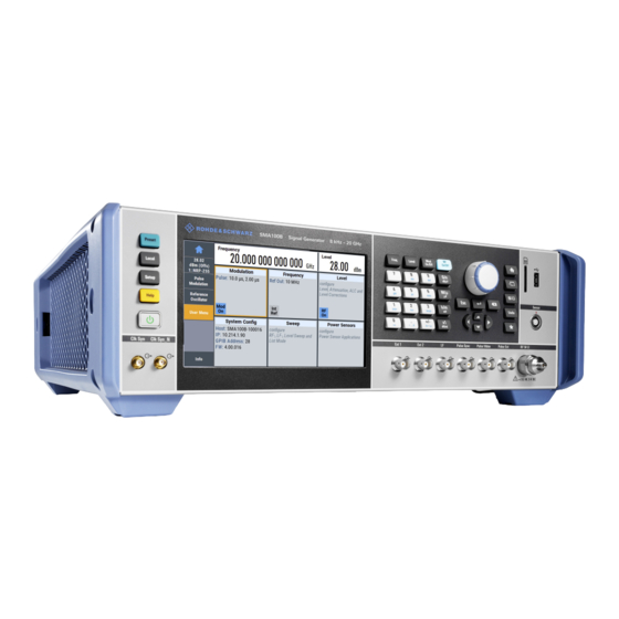
R&S SMA100B. Most of the connectors are at the rear panel and are described in Chapter 3.2.2, "Rear panel tour", on page 43. Figure 3-2: Front panel view of the R&S SMA100B RF Signal Generator with height unit 2HU (option R&S SMAB-B92) Utility keys, page 38 Touchscreen, page 37... -
Page 37: Touchscreen
® Getting started R&S SMA100B Instrument tour On/Standby, page 38 Utility keys, page 38 Touchscreen, page 37 Keypad, page 38 Function keys, page 38 Navigation controls, page 39 Display keys, page 40 SD card slot, page 40 USB connector, page 40... -
Page 38: Utility Keys
Getting started R&S SMA100B Instrument tour 3.2.1.2 Utility keys The utility keys set the R&S SMA100B to a defined state, and provide access to basic settings and information on assistance. Table 3-4: Utility keys Utility Key Assigned functions [Preset] Sets the instrument to a defined state... -
Page 39: Navigation Controls
® Getting started R&S SMA100B Instrument tour Type of key Description Sign key Changes the sign of a numeric parameter. In the case of an alphanu- meric parameter, inserts a "-" at the cursor position. Unit keys These keys add the selected unit to the entered numeric value and com- plete the entry. -
Page 40: Navigation Keys
® Getting started R&S SMA100B Instrument tour Navigation keys As an alternative to the rotary knob or the touchscreen, you can use the navigation keys to navigate through dialog boxes, diagrams, or tables. Table 3-8: Navigation keys Type of key... -
Page 41: Sensor
Sensor Connector for R&S NRP sensors. A power sensor is connected to the R&S SMA100B by inserting the male connector. To disconnect, pull the connector by its sleeve. You cannot disconnect the sensor simply by pulling at the cable or the rear part of the connector. -
Page 42: Pulse Signal Connectors
® Getting started R&S SMA100B Instrument tour The PC 1.85 mm male connector for up to 67 GHz comes with a protective 1.85 mm female adapter to prevent the sensitive connector from damage. It is available as a spare part, and can be replaced if damaged. Contact your Rohde &... -
Page 43: Rear Panel Tour
19 = RF, page 46 9 10 Figure 3-6: Rear panel view of the R&S SMA100B RF Signal Generator with height unit 3HU (option R&S SMAB-B93) = Serial number (six digits in the string 1419.8888.02-<serial number>-<checksum>) IEC 625/IEEE 488, page 44... -
Page 44: Connectors
General purpose interface bus (GPIB) interface for remote control of the instrument. The interface is in compliance with the standards IEC 625, IEEE 488 and SCPI. Use this interface to connect a computer for remote control of the R&S SMA100B. To set up the connection, use high-quality shielded cables. See "Cable selection and elec-... - Page 45 This connector is bidirectional. Used as: ● "Input": enables you to stop a sweep triggered by an external network analyzer. ● "Output": enables the R&S SMA100B to stop the sweep of an external network analyzer. Marker User1 Output signal for marker or trigger signal.
-
Page 46: Trying Out The Instrument
32 3.3 Trying out the instrument This chapter introduces the first steps with the R&S SMA100B. It shows how to oper- ate and configure the instrument using simple examples. The complete description of the functionality and its usage is given in the R&S SMA100B user manual. Basic instru- ment operation is described in Chapter 3.4, "Instrument... - Page 47 Getting started R&S SMA100B Trying out the instrument 1. On the R&S SMA100B front panel, press the [Preset] key to set a defined initial instrument state. 2. Set the frequency: a) In the "Status Bar", tap the "Frequency" field. b) On the on-screen keypad, enter "6" and press the "GHz" key.
- Page 48 Trying out the instrument The blue colored "RF On" icon indicates that the RF output is activated. The R&S SMA100B provides the 6 GHz signal at the RF A connector at the front panel. Figure 3-7: Generating an unmodulated signal...
-
Page 49: Generating An Rf Frequency Sweep Signal
SMA100B Trying out the instrument ® Connect RF of the R&S SMA100B to a signal analyzer, for example R&S FSW, to dis- play the generated signal. For the required settings of the signal analyzer, refer to its user manual or its online help. - Page 50 6. In the "General" tab, activate the frequency sweep with "State > On". 7. Close the sweep dialog. (Alternatively, tap the "Home" button to minimize the dialog. The R&S SMA100B indicates the "Sweep" dialog as active dialog in the task bar.) 8.
-
Page 51: Saving And Recalling Settings
® Getting started R&S SMA100B Trying out the instrument 3.3.3 Saving and recalling settings To restore the results of our measurements later, we save the instrument settings in a file. To save the instrument settings in a file We assume, a test configuration as described in Chapter 3.3.2, "Generating an RF fre-... - Page 52 ® Getting started R&S SMA100B Trying out the instrument 4. In the "Save/Recall" dialog, select "Operation Mode > Recall". Navigate to the directory the file is saved in and select the MyTestSignal file. 5. Tap the "Recall" button. All instrument settings are restored and the display resembles Chapter 3.3.2, "Gen-...
-
Page 53: Instrument Control
See also Chapter 11, "File and data management", on page 308. 3.4 Instrument control This chapter provides an overview on how to work with the R&S SMA100B. It covers the following topics: ● Possible ways to operate the instrument..............54 ●... -
Page 54: Possible Ways To Operate The Instrument
"Remote operation over VNC", on page 63. 3.4.2 Means of manual interaction For the manual interaction with the R&S SMA100B, you have several methods that you can use as an alternative to perform a task: ● Touchscreen: Touchscreen operation is the most direct way to interact. Almost all control ele- ments and actions on the screen are based on the standard operating system con- cept. -
Page 55: Understanding The Display Information
● Using a key on the instrument or on a keyboard 3.4.3 Understanding the display information The home screen of the R&S SMA100B displays all main settings and generator states, divided into three main operation areas. Figure 3-9: Home screen 1 = Taskbar/softkey bar with "Home"... -
Page 56: Status Bar
The status bar at the top of the screen indicates the RF frequency and the level of the output signal provided to the DUT. You can set both parameters directly here. 3.4.3.2 Tile diagram The tile diagram is the main entry to the settings of the R&S SMA100B. Tile Access to: ●... -
Page 57: Additional Display Characteristics
● Info line The "Info line" shows brief status information and error messages. It appears when an event generates a message. If selected, the R&S SMA100B shows information on static errors and the error history. ● Key parameters indicated in tab labels Most dialogs are divided into tabs with logically grouped parameters. -
Page 58: Accessing The Functionality
® Getting started R&S SMA100B Instrument control ● Progress indicators A busy icon indicates a currently running process. If a process takes some time, a progress bar shows the current state. ● Context-sensitive menus Within the entire screen display, including single parameters, you can access con- text-sensitive menus that provide some additional functions. -
Page 59: Entering Data
® Getting started R&S SMA100B Instrument control ● Tap the required tile, and then the menu entry. ● Tap the minimized view (button) on the taskbar. Some of the utility keys access a dedicated dialog, too. To minimize a dialog box 1. -
Page 60: Entering Numeric Parameters
The unit is added to the entry. Tip: For quick unit change, you can enter shortcuts, e.g. for a frequency value 1e8h for 100 MHz. For an overview of shortcuts supported by the R&S SMA100B, see Chapter C, "Unit shortcuts", on page 782. -
Page 61: Getting Information And Help
® Getting started R&S SMA100B Instrument control "Redo" restores a previously undone action. 3.4.6 Getting information and help In some dialog boxes, graphics are included to explain the way a setting works. For further information, you can use the following sources: ●... -
Page 62: Remote Control
The corresponding help topic is displayed. 3.4.7 Remote control In addition to working with the R&S SMA100B interactively, located directly at the instrument, it is also possible to operate and control it from a remote PC. The R&S SMA100B supports various methods for remote control: ●... -
Page 63: Remote Operation Over Vnc
Thus, remote operation of the instrument is possible. Instrument control from a remote computer To access the basic utility functions of the R&S SMA100B, perform a right mouse click the block diagram and select "Key Emulation". A key panel to the right of the block diagram gives access to the utility functions provi- ded by the front panel keys. -
Page 64: Rf Signal Configuration
Chapter 5, "Analog modulations", on page 81. The R&S SMA100B allows you to provide the RF signal with constant or varying fre- quencies and/or amplitudes at the output: ● Constant frequency and level (CW/Fixed mode) The RF output signal has the set frequency and level. -
Page 65: Activating Rf Signal Output
® RF signal configuration R&S SMA100B How to set the frequency and level The RF signal is based on a list of predefined frequency and level values pairs and step widths. Chapter 7, "List and sweep mode", on page 171. - Page 66 Press the [Level] key 2. Enter the values as required. The R&S SMA100B indicates the frequency and level settings in the status bar of the home screen, and shows active functions and parameters of the RF signal in the "Fre- quency"...
-
Page 67: Phase Continuous Frequency
RF Out 4.3 Phase continuous frequency The R&S SMA100B enables you to generate a phase continuous RF signal over a cer- tain frequency range. In this mode, the output sine wave signal shows no phase dis- continuity or glitch when changing the frequency, e.g in sweep mode. -
Page 68: Rf Connector Settings
® RF signal configuration R&S SMA100B RF connector settings Before setting the parameters and activating the phase continuous mode, turn off aci- tive sweeps. 1. If the "RF Frequency Sweep" is running, select "Sweep" > "RF Frequency Sweep". 2. Turn off "State". - Page 69 ® RF signal configuration R&S SMA100B RF connector settings The "RF Connectors" dialog shows the assignment of the logical signals to the con- nectors. The connectors displayed depend on the options installed. 2. Select a "Signal" to access the corresponding settings dialog or directly set signal characteristics.
- Page 70 ® RF signal configuration R&S SMA100B RF connector settings Settings: Signal..........................70 Connector........................71 Show Connector......................71 Signal Displays the signal that is assigned to the connector. Selecting a signal accesses the settings dialog for configuring the signal, or setting sig- nal characteristics directly.
-
Page 71: Rf Frequency Settings
® RF signal configuration R&S SMA100B RF frequency settings "Ref. Freq. Output" Output of the internal reference signal, see Chapter 9.3, "Reference output settings", on page 298 . "Signal Valid" / "Signal Valid Neg." Automatically generated output signal that identifies a valid signal time (level and frequency) for all analog modulation signals. - Page 72 ® RF signal configuration R&S SMA100B RF frequency settings The "Frequency" tile indicates the reference frequency, current frequency offset and multiplier values, and phase offset value. In the "RF Frequency" dialog, you can configure: ● RF frequency, incl. an offset or multiplication factor of a downstream instrument ●...
- Page 73 The "Frequency" value displayed in the status bar is the resulting frequency, as it is at the output of the downstream instrument. The frequency at the R&S SMA100B RF out- put is not changed. "RF frequency and level display with a downstream instrument"...
-
Page 74: Rf Level Settings
® RF signal configuration R&S SMA100B RF level settings Remote command: on page 648 [:SOURce<hw>]:FREQuency:STEP[:INCRement] on page 688 [:SOURce<hw>]:POWer:STEP[:INCRement] 4.6 RF level settings Access: 1. Select "Level" > "RF Level". In the "RF Level" dialog, you can configure the offset-free level, the level limit, and the step width for varying the level with the rotary knob. -
Page 75: Rf State/Rf On
® RF signal configuration R&S SMA100B RF level settings The "Level" tile indicates the level limit, the user correction status and current cor- rection value, current setting characteristics incl. mode. The remote commands required to define the settings are described in Chap- ter 14.16.11, "SOURce:POWer... -
Page 76: Limit
The "Level" value displayed in the status bar is the resulting level, as it is at the output of the downstream instrument. The level at the R&S SMA100B RF output is not changed. "RF frequency and level display with a downstream instrument"... -
Page 77: Harmonic Filter
Provides a linear output power that is uninterrupted over a wide dynamic range. Note: The R&S SMA100B supports this characteristic at frequencies above 52 MHz. If you select the setting at lower frequencies (≤52 MHz), the instrument reports a settings conflict. -
Page 78: Rf Phase Settings
® RF signal configuration R&S SMA100B RF phase settings Readjust Recalculates and adjusts the internal switch positions of the RF chain according to the current level. In "External ALC" mode, "Readjust" triggers the detector offset zeroing, seeChap- ter 8.2.2, "How to set up an external ALC",... - Page 79 Phase Continuous Active Activates generation of a phase continuous frequency signal. The R&S SMA100B generates a phase continuous output sinewave, i.e. without phase discontinuity or glitch when changing the frequency. For a given RF frequency, the frequency range is limited.
- Page 80 ® RF signal configuration R&S SMA100B RF phase settings Frequency Range Selects the mode that determines the frequency range for the phase continuity of the RF signal. The available frequency range depends on the selected mode and is limited by the res- olution of the used synthesizer.
-
Page 81: Analog Modulations
PhiM for example, vary one property of the carrier proportional to the instantaneous amplitude of the modulating signal. Signal sources If fully equipped, the R&S SMA100B modulates signals from the following sources: ● Internal modulation source User Manual 1178.3834.02 ─ 09... - Page 82 ® Analog modulations R&S SMA100B Modulation types and signal sources – Two LF generators Each of the LF generators provides a modulation signal with sine, pulse, trian- gle or trapezoid shape. – Noise generator The noise generator supplies white noise with selectable bandwidth and distri- bution.
- Page 83 DC, the RF output signal behaves according to: – input signal = 0 V: the RF output amplitude corresponds to the level value set in the R&S SMA100B – input signal = +1 V: the output level increases up to the maximum value given by the set modulation sensitivity –...
-
Page 84: Activating Analog Modulations
® Analog modulations R&S SMA100B Modulation settings – excludes PhiM, avionics and pulse modulation – disables automatic level control (ALC) – can not be operated with an external modulation signal For more information, see data sheet. 5.3 Activating analog modulations ►... - Page 85 ® Analog modulations R&S SMA100B Modulation settings Access: ► Select "Modulation" > "Pulse Modulation". The "Pulse Modulation" dialog contains all parameters required to configure the pulse modulator and the pulse generator. It also displays the pulse signal graphically. For an overview of the supported signals sources and related connectors, see Chap- ter 5.2, "Modulation types and signal...
-
Page 86: Fm, Phim And Am Modulation Settings
Flattens the slew rate, resulting in longer rise / fall times. Use this mode if you are working with devices that are sensitive to steep slopes. Note: The R&S SMA100B supports this functionality up to a certain frequency, depending on the installed frequency options, see also "Interactions and characteristics"... -
Page 87: Source State
® Analog modulations R&S SMA100B Modulation settings Source State..........................87 Source...........................87 settings........................88 └ Deviation......................88 └ Deviation Mode....................88 └ Total Deviation....................88 └ Ratio Path2/Path1...................88 └ Mode....................... 89 PhiM settings.........................89 └ Deviation......................89 └ Deviation Mode....................89 └ Total Deviation....................90 └... -
Page 88: Fm Settings
Total Deviation. "Fixed Ratio" Couples the deviation ratio of both paths. If you change the deviation of any path, the R&S SMA100B adjusts the value of the other path. Remote command: on page 575 [:SOURce<hw>]:FM:DEViation:MODE Total Deviation ← FM settings... -
Page 89: Mode
Total Deviation. "Fixed Ratio" Couples the deviation ratio of both paths. If you change the deviation of any path, the R&S SMA100B adjusts the value of the other path. Remote command: on page 580 [:SOURce<hw>]:PM:DEViation:MODE User Manual 1178.3834.02 ─ 09... -
Page 90: Total Deviation
® Analog modulations R&S SMA100B Modulation settings Total Deviation ← PhiM settings Deviation Mode = Fixed Total, sets the sum of the signal deviation for path 1 and path 2. Deviation of both paths always sum up to the value of the total deviation. -
Page 91: Mode
(Option: R&S SMAB-K721) Performs amplitude modulation with a higher dynamic range. The R&S SMA100B provides a special exponential amplitude modu- lation system optimized for highest dynamic range. You can use the scan mode to emulate level behaviors of transmitter/receiver systems with rotating antennas. -
Page 92: Depth
The deviation sum of both paths is 100% in total. When the sum is exceeded, the R&S SMA100B reports a settings conflict, but does not change the settings. "Uncoupled" Enables you to adjust the deviation depth for each path independ- ently. -
Page 93: Chirp Modulation
A chirp is a signal with increasing or decreasing frequency over time. The R&S SMA100B always couples the chirp modulation with the pulse modulation. It generates the modulation signals for FM and pulse modulator, and synchronizes the signals internally. -
Page 94: Chirp Modulation Settings
® Analog modulations R&S SMA100B Modulation settings The nominal level is used for typically 3 ms to 5 ms after level or frequency setting, if: ● No attenuator is fitted. ● "High Power" mode is enabled. ● "Auto" mode is enabled, and if the level is in the range of the high power, i.e. the mechanical relay bypass is switched. -
Page 95: Chirp Modulation
® Analog modulations R&S SMA100B Modulation settings Chirp modulation Access: ► Select "Modulation" > "Chirp Modulation". The "Chirp Modulation" dialog contains the parameters for configuring the modula- tion and trigger settings. State..........................95 Direction........................95 Pulse Period........................96 Bandwidth........................96 Trigger Mode......................... 97 Pulse Width........................ - Page 96 The maximum bandwidth depends on the installed frequency option and the RF fre- quency. If the bandwidth exceeds the RF frequency, or the frequency is out of the bandwidth range, the R&S SMA100B sets the maximum bandwidth and generates an error message.
-
Page 97: Pulse External / Trigger
[:SOURce<hw>]:CHIRp:TRIGger:MODE Pulse Width Sets the width of the generated pulse. The pulse width must be at least 1 us less than the set pulse period. Option R&S SMA100B-K23 provides a higher resolution. For more information, see data sheet. Remote command: on page 571 [:SOURce<hw>]:CHIRp:PULSe:WIDTh... -
Page 98: Pulse Generator
® Analog modulations R&S SMA100B Modulation settings 2. Select "Pulse External / Trigger". The "Pulse External / Trigger" dialog contains the parameters for configuring the externally applied pulse and trigger signals. Show Connector......................98 Show Connector Accesses a dialog that displays the physical location of the selected connector on the front/rear panel of the instrument. -
Page 99: Pulse Generator > General Settings
® Analog modulations R&S SMA100B Modulation settings The "Pulse Generator" tab contains the settings for creating the pulse modulation signal internally. ● Pulse generator > general settings................. 99 ● Pulse generator > pulse train settings..............104 ● Import/export list files.................... 108 5.4.4.1... - Page 100 ® Analog modulations R&S SMA100B Modulation settings Pulse Mode Sets the operating mode of the pulse generator. Depending on the selection, the instru- ment displays the associated parameters. "Single" Generates a single pulse in one pulse period. 1 = Pulse delay...
- Page 101 ® Analog modulations R&S SMA100B Modulation settings "Train" Option: R&S SMAB-K27 Generates a user-defined pulse train. 1 = 1st pulse: On-time 2 = 1st pulse: Off-time 3 = 1st pulse: pulse period 4 = 2nd pulse: repeated 3 times 5 = 3rd pulse 6 = 4th pulse Chapter 5.4.4.2, "Pulse generator >...
- Page 102 ® Analog modulations R&S SMA100B Modulation settings "Ext Triggered" Generates the pulse signal each time an external trigger event occurs. Example: Generation of single pulse signal ("Pulse Mode = Sin- gle") using "Trigger Mode = Ext Triggered" = External trigger signal input with "Trigger Input Polarity = Normal" (the positive...
- Page 103 ® Analog modulations R&S SMA100B Modulation settings = Pulse signal = Trigger signal during double pulse generation is without effect Δt = Trigger delay between the trigger and the sync signal start; see data sheet delay = "Double Pulse Delay = 200 ns"; the first pulse starts without a delay = "Double Pulse Width = 100 ns"...
-
Page 104: Pulse Generator > Pulse Train Settings
® Analog modulations R&S SMA100B Modulation settings Double Pulse Width Sets the width of the second pulse. Remote command: on page 585 [:SOURce<hw>]:PULM:DOUBle:WIDTh Pulse Delay Sets the pulse delay. The pulse delay determines the time that elapses after a trigger event before pulse modulation starts. - Page 105 ® Analog modulations R&S SMA100B Modulation settings Access: 1. Select "Modulation" > "Pulse Modulation > Pulse Generator" > "Pulse Mode = Train". 2. Select "Pulse Train Data". 3. Select an existing file or select "New" to create one. 4. Define the filename.
- Page 106 ® Analog modulations R&S SMA100B Modulation settings Note that you have to create a pulse train file first. ● Externally Create a pulse train sequence as a CSV file with Microsoft Excel, with a Notepad or a similar tool, save it with the predefined extension. Transfer the file to and load it into the instrument.
- Page 107 ® Analog modulations R&S SMA100B Modulation settings Edit Pulse Train Data Accesses the build-in table editor to define a new pulse train file or edit an existing one. "On-Time, µs/Off-Time,µs" Sets the pulse on and pulse off time. "Count" Sets the number of repetitions of an "On-/ Off-Time" value pair.
-
Page 108: Import/Export List Files
® Analog modulations R&S SMA100B Modulation settings To fill the table, select "Fill". Note: Once you enter a value or fill a column, the editor automatically adds preset val- ues in the other columns. This functionality protects against data loss, otherwise incomplete rows will be lost when saving. - Page 109 ® Analog modulations R&S SMA100B Modulation settings 2. Select "Import/Export". Figure 5-1: Im-/Export dialog (example with UCOR settings) The "Import/Export" dialog contains all functions and settings to import externally created list data or to export it accordingly. You can process and store a list in the formats *.txt (ASCII), or *.csv (plain text with identical sequence of fields).
- Page 110 ® Analog modulations R&S SMA100B Modulation settings on page 676 [:SOURce<hw>]:LIST:DEXChange:AFILe:SEParator:COLumn on page 640 [:SOURce<hw>]:CORRection:DEXChange:AFILe:EXTension [:SOURce<hw>]:CORRection:DEXChange:AFILe:SEParator:DECimal on page 641 [:SOURce<hw>]:CORRection:DEXChange:AFILe:SEParator:COLumn on page 641 on page 590 [:SOURce<hw>]:PULM:TRAin:DEXChange:AFILe:EXTension [:SOURce<hw>]:PULM:TRAin:DEXChange:AFILe:SEParator:DECimal on page 591 [:SOURce<hw>]:PULM:TRAin:DEXChange:AFILe:SEParator:COLumn on page 591 Select (ASCII) Source/Select (ASCII) Destination In "Mode >...
-
Page 111: Pulse Graph
® Analog modulations R&S SMA100B Modulation settings 5.4.5 Pulse graph Option: see Chapter 5.1, "Required options", on page 81. Access: ► Select "Modulation" > "Pulse Modulation > Pulse Graph". The pulse graph is the graphical representation of the current pulse signal. -
Page 112: Pulse External / Trigger Settings
® Analog modulations R&S SMA100B Modulation settings 5.4.6 Pulse external / trigger settings Access: ► Select "Modulation" > "Pulse Modulation > Pulse External / Trigger". The dialog specifies some characteristics of the Pulse Ext connector. This connector is common for the pulse generator and the pulse modulator. For an overview, see "Input and output connectors"... -
Page 113: Fm, Phim And Am Modulation Sources
® Analog modulations R&S SMA100B Modulation settings Show Connector Accesses a dialog that displays the physical location of the selected connector on the front/rear panel of the instrument. 5.4.7 FM, PhiM and AM modulation sources Access: ► Select "Modulation > Modulation Sources". -
Page 114: State (Lf Frequency Sweep)
® Analog modulations R&S SMA100B Modulation settings The internal LF signal can the modulation signal source for any of the analog mod- ulations. The LF signal applies to all modulations which use the internal modulation signal. Therefore, any modification of the LF signal immediately affects all currently active modulations. - Page 115 ® Analog modulations R&S SMA100B Modulation settings "Square" 1 = Period "Pulse" 1 = Pulse width 2 = Pulse period "Triangle" 1 = Triangle rise 2 = Triangle period User Manual 1178.3834.02 ─ 09...
-
Page 116: Frequency
® Analog modulations R&S SMA100B Modulation settings "Trapezoid" 1 = Trapezoid rise 2 = Trapezoid high 3 = Trapezoid period 4 = Trapezoid fall Remote command: on page 658 [:SOURce<hw>]:LFOutput<ch>:SHAPe Frequency Sets the frequency of the LF generator for sine signals. -
Page 117: Source > External Settings
® Analog modulations R&S SMA100B Modulation settings Triangle Rise Sets the time required for the triangle signal to change from low level to high level. Remote command: on page 661 [:SOURce<hw>]:LFOutput<ch>:SHAPe:TRIangle:RISE Trapezoid Rise / Fall Sets the time required for the trapezoid signal to change from low level to high level, and vice versa. - Page 118 ® Analog modulations R&S SMA100B Modulation settings Settings Coupling (AC/DC)......................118 Impedance........................118 Bandwidth........................118 Show Connector......................118 Coupling (AC/DC) Selects the coupling mode (AC or DC) for the external signal. "AC" Disconnects the DC voltage component and uses only the AC com- ponent of the modulation signal.
-
Page 119: Source > Noise Generator Settings
® Analog modulations R&S SMA100B Modulation settings 5.4.7.3 Source > noise generator settings Access: ► Select "Modulation" > "Modulation Sources > Noise Generator". The "Noise Generator" settings contain all parameters to configure the signal of the internal noise generator. Settings Distribution........................119... -
Page 120: Lf Signal Output Settings
® Analog modulations R&S SMA100B Modulation settings 5.4.8 LF signal output settings Access: ► Select "Modulation" > "LF Output". In the "LF Output" tab, you can configure the signal at the LF outputs, determine the output voltage or add a DC offset. Activate both paths to output the sum signal of the two sources. - Page 121 These signal generators come with an LF generator source impedance of 10 Ohm which is not available with the R&S SMA100B. The set LF generator load impedance enables the R&S SMA100B to emulate the 10 Ohm LF generator source impedance of these generators by a corresponding increase of the open circuit LF generator output voltage.
-
Page 122: Overview
® Analog modulations R&S SMA100B Modulation settings Remote command: n.a. Noise Level Access: ● Select "Modulation" > "Output > Noise Level". Noise Density ← Noise Level Indicates the level of the noise signal for a bandwidth of 1 Hz (relative). - Page 123 ® Analog modulations R&S SMA100B Modulation settings Access: ► Select "Modulation" > "Modulation Sources > Overview". Blue color = Active output signal (AM and FM) Gray color = Inactive output signal (LF Out) Miniature graph = Indicates an active source Connectors = Indicate a connector (e.g.
-
Page 124: How To Generate An Amplitude Modulated Signal
® Analog modulations R&S SMA100B How to generate a pulse modulated signal Label for the amplitude modulation settings in the overview. Remote command: n.a. FM/PhiM Selects the modulation signal to be assigned to the output. You can assign the fre- quency or phase modulated signal. -
Page 125: How To Generate A Pulse Train Modulated Signal
® Analog modulations R&S SMA100B How to generate a pulse train modulated signal To set the frequency and level of the RF signal 1. Press [Preset]. 2. In the status bar, set "Frequency = 4 GHz". 3. Set "Level = -25 dBm". - Page 126 ® Analog modulations R&S SMA100B How to generate a pulse train modulated signal 4. Select an existing file or select "New" to create one. 5. Define the filename. Select "Edit Pulse Train Data", if the file is empty or to control and change the val- ues.
-
Page 127: Avionic Standards
® Avionic standards R&S SMA100B About the Avionics options 6 Avionic standards The R&S SMA100B supports avionic standards VOR, ILS and ADF. Contents ● Required options....................127 ● About the Avionics options..................127 ● VOR configuration and settings................133 ● ILS configuration and settings................142... -
Page 128: Required Options
® Avionic standards R&S SMA100B About the Avionics options 6.2.1 Required options The basic equipment layout for generating avionics standards signals includes the options: ● Base unit ● Baseband real-time extension (R&S SMAB-K520) ● Digital standard ILS (R&S SMAB-K151) ●... -
Page 129: Instrument Landing System (Ils)
102Y 115.55 116Y 116.95 Related Settings For VOR settings at the R&S SMA100B, see Chapter 6.3, "VOR configuration and set- tings", on page 133. 6.2.3 Instrument landing system (ILS) The instrument landing system is used during the landing approach and monitors the correct approach path to the runway. - Page 130 ® Avionic standards R&S SMA100B About the Avionics options Figure 6-1: Approach navigation using instrument landing system (ILS) [1MA193] An ILS system consists of three independent subsystems: ● A glide slope for vertical guidance. ● A localizer for horizontal guidance.
- Page 131 ® Avionic standards R&S SMA100B About the Avionics options Localizer The localizer transmitter is located near the end of the runway (nearest to the start of the aircraft approach). Typically, horizontally aligned antennas transmit two intersecting main beams beside one another at carrier frequencies between 108 MHz and 112 MHz...
- Page 132 Middle marker flashes AMBER in the cockpit at 1300 Hz (“hurried” tone). ● Inner marker flashes WHITE in the cockpit at 3000 Hz (“urgent” tone). Related Settings For ILS settings at the R&S SMA100B, see the following sections: ● Chapter 6.4.2, "ILS glide slope settings", on page 145 ●...
-
Page 133: Automatic Direction Finder (Adf)
The ADF determines the direction to the NDB station relative to the aircraft and is used for instrument approaches (autopilot). It provides additional information to other naviga- tion equipment, e.g. VOR. Related Settings For ADF settings at the R&S SMA100B, see Chapter 6.5, "ADF configuration and set- tings", on page 165. -
Page 134: General Settings
"Avionic: ADF" for enabled ADF modulation Changing a parameter in the avionic standards causes an instant signal change in the R&S SMA100B. There is no extra measurement cycle to calculate the RMS value of the baseband signal to set the correct RF level. - Page 135 ® Avionic standards R&S SMA100B VOR configuration and settings Carrier Frequency....................... 136 ICAO Channel......................136 AM........................136 State Activates the avionic standard. Activation of the standard deactivates a previously active avionic standard. The "VOR/ILS > Carrier Frequency" setting is applied automatically to the RF Frequency and displayed in the status bar.
- Page 136 ® Avionic standards R&S SMA100B VOR configuration and settings "ICAO" Activates variation in predefined steps according to standard VOR transmitting frequencies (see Table 6-1). The start value can be selected in the field "ICAO Channel". Remote command: on page 631 [:SOURce<hw>]:VOR:FREQuency:MODE...
-
Page 137: Signal Settings
® Avionic standards R&S SMA100B VOR configuration and settings 6.3.2 Signal settings Access: ► Select "VOR > Signal". This dialog provides access to signal settings of the VOR modulation signal. Settings Mode........................... 137 VAR/REF Frequency....................138 Depth........................138 Subcarrier Frequency....................138 Subcarrier Depth......................138 Deviation...................... - Page 138 ® Avionic standards R&S SMA100B VOR configuration and settings VAR/REF Frequency Sets the frequency of the VAR signal and the REF signal. As the two signals must have the same frequency, the setting is valid for both signals. Remote command: on page 634 [:SOURce<hw>]:VOR:VAR:FREQuency...
-
Page 139: Position Settings
® Avionic standards R&S SMA100B VOR configuration and settings 6.3.3 Position settings Access: ► Select "VOR > Position". This dialog provides access to position settings related to the VOR modulation sig- nal. Settings Bearing Angle......................139 Direction........................139 Bearing Angle Sets the phase angle between the 30 Hz VAR signal and the 30 Hz reference signal. -
Page 140: Com/Id Settings
® Avionic standards R&S SMA100B VOR configuration and settings 6.3.4 COM/ID settings Access: ► Select "VOR > COM/ID" This dialog comprises COM/ID signal settings related to the VOR signal. Settings COM/ID State......................140 Code..........................140 Period..........................141 Frequency........................141 Depth...........................141 Time Schema......................141 Length........................141... - Page 141 ® Avionic standards R&S SMA100B VOR configuration and settings The COM/ID tone is sent according to the selected code, see Chapter D, "Morse code settings", on page 784. If no coding is set, the COM/ID tone is sent uncoded (key down).
-
Page 142: Ils Configuration And Settings
® Avionic standards R&S SMA100B ILS configuration and settings Symbol Space Requires "Time Schema > User". Sets the length of the Morse code symbol space. Remote command: on page 629 [:SOURce<hw>]:VOR:COMid:SYMBol Letter Space Requires "Time Schema > User". Sets the length of a Morse code letter space. - Page 143 "Avionic: ADF" for enabled ADF modulation Changing a parameter in the avionic standards causes an instant signal change in the R&S SMA100B. There is no extra measurement cycle to calculate the RMS value of the baseband signal to set the correct RF level.
- Page 144 ® Avionic standards R&S SMA100B ILS configuration and settings State Activates the avionic standard. Activation of the standard deactivates a previously active avionic standard. The "VOR/ILS > Carrier Frequency" setting is applied automatically to the RF Frequency and displayed in the status bar.
-
Page 145: Ils Glide Slope Settings
® Avionic standards R&S SMA100B ILS configuration and settings 6.4.2 ILS glide slope settings Access: 1. Select "ILS > General". 2. Select "ILS Component > Glide Slope". Settings ● General settings....................145 ● Signal settings.......................147 ● Amplitude settings....................149 6.4.2.1 General settings Access: 1. - Page 146 ® Avionic standards R&S SMA100B ILS configuration and settings Carrier Frequency Mode Sets the mode for the carrier frequency of the signal. Select "Carrier Frequency Mode > ICAO" to set a standard ILS frequency channel. If you want to couple carrier frequencies of ILS glide slope and localizer components,...
-
Page 147: Signal Settings
® Avionic standards R&S SMA100B ILS configuration and settings "EXT (MOD AM)" Selects the external source. The external signal is added to the inter- nal signal. Switching off the internal source is not possible. The exter- nal signal is input via the Ext connector. The sensitivity is 10 mV per percent modulation depth. - Page 148 ® Avionic standards R&S SMA100B ILS configuration and settings "90 Hz" Amplitude modulation of the output signal with the upper lobe signal component (90 Hz signal content) of the ILS glide slope signal. The modulation depth of the 90 Hz signal results from the settings of...
-
Page 149: Amplitude Settings
® Avionic standards R&S SMA100B ILS configuration and settings 6.4.2.3 Amplitude settings Access: 1. Select "ILS Component > Glide Slope", see Chapter 6.4.2, "ILS glide slope set- tings", on page 145. 2. Select "ILS > Amplitude". This dialog comprises amplitude settings related to the ILS glide slope component of the ILS signal. - Page 150 ® Avionic standards R&S SMA100B ILS configuration and settings Fly Mode Selects the simulation mode for the ILS glide slope modulation signal. A change of the setting automatically changes the sign of the DDM value. This setting simulates the direction in which the pilot has to correct the course.
-
Page 151: Ils Localizer Settings
® Avionic standards R&S SMA100B ILS configuration and settings A variation of the value automatically leads to a variation of the DDM value and the instrument current. Remote command: on page 606 [:SOURce<hw>]:ILS[:GS|GSLope]:DDM:LOGarithmic DDM Percent Sets the difference in depth of modulation between the upper lobe (90 Hz) and the lower lobe (150 Hz) tone of the ILS glide slope modulation signal. -
Page 152: General Settings
® Avionic standards R&S SMA100B ILS configuration and settings 6.4.3.1 General settings Access: 1. Select "ILS Component > Localizer", see Chapter 6.4.3, "ILS localizer settings", on page 151. 2. Select "ILS > General". This dialog comprises carrier frequency settings related to the ILS localizer compo- nent of the ILS signal. - Page 153 ® Avionic standards R&S SMA100B ILS configuration and settings Sets the carrier frequency of the signal. Remote command: on page 617 [:SOURce<hw>]:ILS:LOCalizer:FREQuency ICAO Channel Requires "Carrier Frequency Mode > ICAO". Sets the ICAO channel and the corresponding transmitting frequency. If avionic standard modulation is activated and you change the "RF Frequency", the frequency value of the closest ICAO channel is applied automatically.
-
Page 154: Signal Settings
® Avionic standards R&S SMA100B ILS configuration and settings 6.4.3.2 Signal settings Access: 1. Select "ILS Component > Localizer", see Chapter 6.4.3, "ILS localizer settings", on page 151. 2. Select "ILS > Signal". This dialog comprises audio signal and modulation settings related to the ILS local- izer component of the ILS signal. -
Page 155: Amplitude Settings
® Avionic standards R&S SMA100B ILS configuration and settings "150 Hz" Amplitude modulation of the output signal with the right lobe (150 Hz) signal component of the ILS localizer signal. The modulation depth of the 150 Hz signal results from the settings of... - Page 156 ® Avionic standards R&S SMA100B ILS configuration and settings 2. Select "ILS > Amplitude". This dialog comprises amplitude settings related to the ILS localizer component of the ILS signal. Settings Mode........................156 Sum of Depth......................156 DDM - SDM Coupling....................157 Step........................157...
- Page 157 ® Avionic standards R&S SMA100B ILS configuration and settings The RMS modulation depth of the sum signal depends on the phase setting of both modulation tones. The "Sum of Depth" and "COM/ID > Depth" must be smaller than 100 %.
-
Page 158: Com/Id Settings
® Avionic standards R&S SMA100B ILS configuration and settings DDM Logarithmic Sets the DDM value in dB. The dB value is calculated according to: DDM dB = 20 × LOG [(SDM + DDM × 100 %) / (SDM - DDM × 100 %)] A variation of the value automatically leads to a variation of the DDM value and the instrument current. - Page 159 ® Avionic standards R&S SMA100B ILS configuration and settings This dialog comprises COM/ID settings related to the ILS localizer component of the ILS signal. Settings COM/ID State......................159 Code..........................159 Frequency........................159 Period..........................159 Depth...........................159 Time Schema......................160 Length........................160 Dash Length........................160 Symbol Space......................160 Letter Space........................160...
-
Page 160: Ils Marker Beacons Settings
® Avionic standards R&S SMA100B ILS configuration and settings Time Schema Sets the time schema of the Morse code for the COM/ID signal. ● "Standard" The set dot length determines the length of the dash, the symbol space and letter space of the Morse code. -
Page 161: General Settings
® Avionic standards R&S SMA100B ILS configuration and settings Settings ● General settings....................161 ● Signal settings.......................162 ● COM/ID settings....................163 6.4.4.1 General settings Access: 1. Select "ILS Component > Marker Beacons", see Chapter 6.4.4, "ILS marker bea- cons settings", on page 160. -
Page 162: Signal Settings
® Avionic standards R&S SMA100B ILS configuration and settings 6.4.4.2 Signal settings Access: 1. Select "ILS Component > Marker Beacons", see Chapter 6.4.4, "ILS marker bea- cons settings", on page 160. 2. Select "ILS > Signal". This dialog comprises signal settings related to the ILS marker beacons compo- nent of the ILS signal. -
Page 163: Com/Id Settings
® Avionic standards R&S SMA100B ILS configuration and settings "On" Modulation of pulsed marker signals (morse coding). The duty cycle, i.e. the marker on- and off-times, depend on the marker signal fre- quency (Table 6-3). Table 6-3: Morse coding for ILS marker beacons marker signals... - Page 164 ® Avionic standards R&S SMA100B ILS configuration and settings Settings COM/ID State......................164 Code..........................164 Period..........................164 Frequency........................164 Depth...........................164 Time Schema......................164 Length........................165 Dash Length........................165 Symbol Space......................165 Letter Space........................165 COM/ID State Enables/disables the COM/ID signal. See also Chapter D, "Morse code settings",...
-
Page 165: Adf Configuration And Settings
® Avionic standards R&S SMA100B ADF configuration and settings The set dot length determines the length of the dash, the symbol space and letter space of the Morse code. ● "User" You can set each length value separately. Remote command: on page 623 [:SOURce<hw>][:ILS]:MBEacon:COMid:TSCHema... -
Page 166: General Settings
Change the carrier frequency to a value within the specified frequency range. Changing a parameter in the avionic standards causes an instant signal change in the R&S SMA100B. There is no extra measurement cycle to calculate the RMS value of the baseband signal to set the correct RF level. - Page 167 ® Avionic standards R&S SMA100B ADF configuration and settings Settings State..........................167 Set To Default......................167 Save/Recall......................... 167 State Activates the avionic standard. Activation of the standard deactivates a previously active avionic standard. The "VOR/ILS > Carrier Frequency" setting is applied automatically to the RF Frequency and displayed in the status bar.
-
Page 168: Com/Id Settings
® Avionic standards R&S SMA100B ADF configuration and settings 6.5.2 COM/ID settings Access: ► Select "ADF > COM/ID". This dialog comprises COM/ID signal settings related to the ADF signal. Settings COM/ID State......................168 Code..........................168 Period..........................169 Frequency........................169 Depth...........................169 Time Schema......................169 Length........................169... - Page 169 ® Avionic standards R&S SMA100B ADF configuration and settings If no coding is set, the COM/ID tone is sent uncoded (key down). Remote command: on page 600 [:SOURce<hw>]:ADF:COMid:CODE Period Sets the period of the COM/ID signal. Remote command: on page 602 [:SOURce<hw>]:ADF:COMid:PERiod...
- Page 170 ® Avionic standards R&S SMA100B ADF configuration and settings Remote command: on page 602 [:SOURce<hw>]:ADF:COMid:SYMBol Letter Space Requires "Time Schema > User". Sets the length of a Morse code letter space. Remote command: on page 601 [:SOURce<hw>]:ADF:COMid:LETTer User Manual 1178.3834.02 ─ 09...
-
Page 171: List And Sweep Mode
A signal generated with varying parameters scans a certain range of varying values of a parameter, with defined start and end points, and can be repeated cyclically. The R&S SMA100B supports two basic methods: ● Sweep mode The instrument generates an RF signal which varies its frequency or level values in discrete steps between the start and end values. - Page 172 ® List and sweep mode R&S SMA100B Figure 7-2: Schematic representation of a signal generated in list mode (global dwell time) The list mode is especially useful in high-speed measurements with fast changing frequency and level settings. Note that the shown diagrams represent the behaviour in theory. In real signal genera- tion, the instruments usually have a blank time when the frequency or level changes.
-
Page 173: Signal Generation And Triggering In The Sweep And List Modes
If the dwell time in sweep or list mode is too short or external trigger signals come too fast, the signal generation delays. As the delay increases, the R&S SMA100B signals an overrun, or even stops sweep or list mode signal generation, if the delay gets too long. - Page 174 ® List and sweep mode R&S SMA100B Signal generation and triggering in the sweep and list modes Auto mode (Sweep/List) Figure 7-3: Auto mode (Sweep/List) ● The instrument generates the signal continuously. ● Trigger mode "Auto" is prerequisite (default). It causes the continuous generation of the sweep signal.
- Page 175 ® List and sweep mode R&S SMA100B Signal generation and triggering in the sweep and list modes Single / Extern Single mode (Sweep/List) Figure 7-4: Single / Extern Single mode (sweep / list ) In single mode, you can specify, that the signal returns to the start value when a sweep cycle has been completed.
- Page 176 ® List and sweep mode R&S SMA100B Signal generation and triggering in the sweep and list modes Table 7-2: Cross-reference between manual and remote control in Single / Extern Single modes (Sweep/List) Manual control mode: Remote commands "Single / Extern Single"...
- Page 177 ® List and sweep mode R&S SMA100B Signal generation and triggering in the sweep and list modes ● Trigger sources: – The rotary knob at the front panel. – The [Arrow] keys at the front panel. – The corresponding remote control commands.
- Page 178 ® List and sweep mode R&S SMA100B Signal generation and triggering in the sweep and list modes Extern Start/Stop mode (sweep) Figure 7-6: Extern Start/Stop mode (sweep) ● The instrument generates the signal continuously. ● Trigger mode "Auto" and "Sweep > State = On" are prerequisite.
- Page 179 ® List and sweep mode R&S SMA100B Signal generation and triggering in the sweep and list modes Manual mode (Sweep/List) The manual mode only applies to remote control. It is not visible in the graphical user interface of the instrument and is described here for completeness.
-
Page 180: About Sweep Mode
® List and sweep mode R&S SMA100B About sweep mode The Retrace function Retrace is a function especially designed for "Single" sweep modes, when the sweep signal follows a sawtooth shape. Working in this mode, the instrument performs a sin- gle sweep cycle when a trigger event occurs. -
Page 181: Correlating Parameters In Sweep Mode
The combined RF sweep functionality processes the signal similar to the Live list mode. The R&S SMA100B sets the frequency and level values simultaneously in the hardware. The difference to the list mode is that the values are not taken from a previ- ously created list, but are calculated using the selected frequency and level ranges, the dwell time and the number of steps. - Page 182 ® List and sweep mode R&S SMA100B About sweep mode Variable Description Next, subsequent sweep frequency step_lin Step size in linear scaling step_log Step size in logarithmic scaling POINts Number of steps within the sweep range Sweep range The sweep range is defined by a start and an end value. How the remaining parame- ters correlate is shown below.
-
Page 183: Sweep Signal Shapes
STARt STOP retained. 7.2.2 Sweep signal shapes The R&S SMA100B supports the following sweep shapes: ● Sawtooth The sweep sequence resembles a sawtooth. One sweep runs from start to stop frequency, or level value respectively. Each subsequent sweep starts again at the start value. -
Page 184: About List Mode
® List and sweep mode R&S SMA100B About list mode Figure 7-8: Sweep signal sawtooth shape 1 = Start value 2 = Stop value 3 = Step size ● Triangle The sweep sequence resembles a triangle. One sweep runs from start to stop value frequency and back. -
Page 185: Significant Parameters And Functions
® List and sweep mode R&S SMA100B Significant parameters and functions arbitrarily, in any order and varying step sizes, within the entire configurable value range of the instrument. Configuration and operation of list mode signals The parameters configuring the RF signal are defined in a list (table) and stored in a file. - Page 186 If the dwell time in sweep or list mode is too short or external trigger signals come too fast, the signal generation delays. As the delay increases, the R&S SMA100B signals an overrun, or even stops sweep or list mode signal generation, if the delay gets too long.
-
Page 187: Sweep Mode Settings
Sweep mode settings Live list processing mode The R&S SMA100B generates the signal directly from the value pairs in the database, and adjusts the hardware settings accordingly. The current instrument state and thus any change during the signal generation directly affects the RF signal. The temporary memory is not used. -
Page 188: Settings Sweep Type
® List and sweep mode R&S SMA100B Sweep mode settings Table 7-7: General settings dialog: Examples of RF Frequency and RF Combined Sweep dialogs > "RF Frequency Sweep" > "RF Combined Sweep" Settings Sweep Type........................ 188 State (RF frequency sweep)..................188 State (RF level sweep)....................189... -
Page 189: State (Rf Level Sweep)
® List and sweep mode R&S SMA100B Sweep mode settings Remote command: on page 643 [:SOURce<hw>]:FREQuency:MODE State (RF level sweep) Activates RF level sweep signal generation. Note: Active RF frequency, RF level or RF combined sweep modes deactivate the LF sweep or List mode and vice versa. -
Page 190: Retrace
® List and sweep mode R&S SMA100B Sweep mode settings Chapter 7.1, "Signal generation and triggering in the sweep and list modes", on page 173. "Auto" Generates a continuously repeating sweep signal directly after acti- vating the sweep mode. The sweep steps are performed automatically, controlled by the dwell time. -
Page 191: Shape
® List and sweep mode R&S SMA100B Sweep mode settings Shape Selects the waveform shape of the sweep signal. "Sawtooth" The sweep runs from start to stop frequency. The subsequent sweep starts at the start value, i.e. the shape of the sweep sequence resem- bles a sawtooth. -
Page 192: Spacing
Remote command: on page 710 [:SOURce<hw>]:SWEep[:FREQuency]:TIME Dwell Time Defines the duration of the individual sweep steps. Note: In case of considerable overrun conditions, the R&S SMA100B turns off the sweep mode. See also Chapter 7.4, "Significant parameters and functions", on page 185. -
Page 193: Trigger Slope
® List and sweep mode R&S SMA100B Sweep mode settings Remote command: RF frequency sweep: on page 703 [:SOURce<hw>]:SWEep[:FREQuency]:DWELl RF level sweep: on page 701 [:SOURce<hw>]:SWEep:POWer:DWELl RF combined sweep: on page 708 [:SOURce<hw>]:SWEep:COMBined:DWELl LF frequency sweep: on page 661 [:SOURce<hw>]:LFOutput:SWEep[:FREQuency]:DWELl Trigger Slope For "Mode = Extern Step/Single", selects the polarity of the active slope of an applied... -
Page 194: Frequency Range Settings
® List and sweep mode R&S SMA100B Sweep mode settings 7.5.2 Frequency range settings Access: 1. Select for example "Sweep" > "RF Frequency Sweep" 2. Select for example "Frequency Range". Table 7-8: Range settings dialog: Examples of RF Frequency and RF Combined Sweep dialogs >... - Page 195 ® List and sweep mode R&S SMA100B Sweep mode settings Span In "RF Frequency Sweep" mode, sets the span of the frequency sweep range. Chapter 7.2.1, "Correlating parameters in sweep mode", on page 181. Remote command: on page 647 [:SOURce<hw>]:FREQuency:SPAN Spacing In "RF and LF Frequency Sweep"...
-
Page 196: Level Range Settings
® List and sweep mode R&S SMA100B Sweep mode settings "Step Logarithmic" The step width is determined logarithmically in %, i.e. as a constant fraction of the current frequency. Remote command: on page 706 [:SOURce<hw>]:SWEep[:FREQuency]:STEP[:LINear] on page 706 [:SOURce<hw>]:SWEep[:FREQuency]:STEP:LOGarithmic on page 664 [:SOURce<hw>]:LFOutput:SWEep[:FREQuency]:STEP[:LINear]... - Page 197 ® List and sweep mode R&S SMA100B Sweep mode settings Step Count In "RF Combined Mode", defines the number of sweeps to be executed in Mode > Sin- gle. To start the sweep cycles, select Execute Single. Remote command: on page 708 [:SOURce<hw>]:SWEep:COMBined:COUNt...
-
Page 198: Output Settings
Provides a linear output power that is uninterrupted over a wide dynamic range. Note: The R&S SMA100B supports this characteristic at frequencies above 52 MHz. If you select the setting at lower frequencies (≤52 MHz), the instrument reports a settings conflict. -
Page 199: Edit Marker Settings
List and sweep mode R&S SMA100B Sweep mode settings The R&S SMA100B supplies the signal at the V/GHz X-Axis connector. "0,25 V/GHz" / Supplies the voltage proportional to the set frequency, derived from " 0,5 V/GHz" / " the selected setting. - Page 200 You can define up to 10 markers, and assign one of them to the output at a time. When the sweep run has reached the marker frequency, the R&S SMA100B acti- vates the marker signal and supplis it at the Marker User1 connector. The duration of the active signal corresponds to the dwell time of a step.
-
Page 201: List Mode Settings
® List and sweep mode R&S SMA100B List mode settings Marker Polarity Sets the polarity of the marker signal. The duration of the active signal is equal to the dwell time of a step. Remote command: on page 710 [:SOURce<hw>]:SWEep:MARKer:OUTPut:POLarity... -
Page 202: General Settings
® List and sweep mode R&S SMA100B List mode settings 7.6.1 General settings Access: ► Select "Sweep" > "List mode". In the "General" tab, you can configure the trigger and dwell time modes for list processing and activate signal generation. - Page 203 668 [:SOURce<hw>]:LIST:DWELl:MODE Global Dwell Time Sets the dwell time for Dwell Time Mode > "Global". Note: In case of considerable overrun conditions, the R&S SMA100B turns off the list mode. See also "Dwell time" on page 186. Remote command: on page 668 [:SOURce<hw>]:LIST:DWELl...
-
Page 204: List Mode Data Settings
® List and sweep mode R&S SMA100B List mode settings "Negative" The falling edge of the trigger signal triggers the instrument. Remote command: on page 652 [:SOURce]:INPut:TRIGger:SLOPe Reset Resets the list to the starting point. Remote command: on page 674 [:SOURce<hw>]:LIST:RESet... -
Page 205: Import/Export Settings
® List and sweep mode R&S SMA100B List mode settings Edit List Mode Data Opens the editor to insert and save data lists with RF frequency, power and dwell time values, see Chapter 7.7, "List editor", on page 207. You find this function also in standard file select dialog, accessed via List Mode Data. - Page 206 ® List and sweep mode R&S SMA100B List mode settings Settings Mode........................... 206 ASCII File Settings...................... 206 Select (ASCII) Source/Select (ASCII) Destination............206 Select Source/Select ASCII Destination..............207 Import / Export......................207 Mode Selects import or export of a data list file. The provided parameters vary according to the selected mode.
-
Page 207: List Editor
® List and sweep mode R&S SMA100B List editor Remote command: on page 675 [:SOURce<hw>]:LIST:DEXChange:AFILe:CATalog? on page 676 [:SOURce<hw>]:LIST:DEXChange:AFILe:SELect on page 640 [:SOURce<hw>]:CORRection:DEXChange:AFILe:CATalog? on page 641 [:SOURce<hw>]:CORRection:DEXChange:AFILe:SELect on page 591 [:SOURce<hw>]:PULM:TRAin:DEXChange:AFILe:CATalog? on page 591 [:SOURce<hw>]:PULM:TRAin:DEXChange:AFILe:SELect Select Source/Select ASCII Destination In "Mode > Export", access the file select dialog that provides standard file handling functions. - Page 208 ® List and sweep mode R&S SMA100B List editor The remote commands required to define the list mode data are described in Chapter 14.16.7, "SOURce:LIST subsystem", on page 665. Access to "Edit User Correction Data": ► "Level" > "User Correction" > "Edit User Cor. Data"...
- Page 209 ® List and sweep mode R&S SMA100B List editor Since the table and navigation functions can be assumed to be known, the following description contains a brief overview, shown by the example of the "Edit List Mdoe Data" dialog. If a function relates to a particular dialog, it is explicitly stated.
- Page 210 ® List and sweep mode R&S SMA100B List editor Edit ← Data handling keys Enables you to insert, or delete a row or ranges within a list, and provides access to a dialog for automatic filling, see "Fill..." on page 107.
-
Page 211: How To Generate A Signal In List Or Sweep Mode
® List and sweep mode R&S SMA100B How to generate a signal in list or sweep mode 7.8 How to generate a signal in list or sweep mode This section shows you how to configure a varying RF output signal for both, the list and sweep modes. - Page 212 ® List and sweep mode R&S SMA100B How to generate a signal in list or sweep mode To configure the list mode and start signal generation 1. In the "General" tab, select "List Mode > Auto". 2. Select "Dwell Time Mode > From List".
-
Page 213: Improving Level Performance
R&S SMA100B Attenuator 8 Improving level performance To adjust the RF output signal to specific needs in your application, the R&S SMA100B offers different functions: ● Attenuator The R&S SMA100B is equipped with a step attenuator that enables you to vary the amplitude of the RF signal in a wide range. -
Page 214: Attenuator Settings
® Improving level performance R&S SMA100B Attenuator However, option R&S SMAB-B36S does not support using the mechanical attenuator below 20 GHz. According to the requirements of your application, you can select different attenuator characteristics. The following are examples of test requirements and the corresponding configuration: ●... - Page 215 "About the attenuator" on page 213. "Mechanical" Selects that the R&S SMA100B uses the mechanical step attenuator over the whole frequency range. The mechanical attenuator is used even for lower frequencies, to achieve a consistent level setting behavior for all frequencies. The electronic step attenuator is disregarded.
-
Page 216: Reverse Power Protection
492 :OUTPut<hw>:PROTection:CLEar 8.2 Automatic level control (ALC) The R&S SMA100B is equipped with an automatic level control (ALC) unit to obtain best RF level accuracy. About ALC ALC is an adaptive control system to stabilize the RF output level. It continuously moni- tors the current level and adjusts it to keep a steady state over temperature and time. - Page 217 This setting enables you to control the RF signal level at a specific point in the sig- nal chain following the signal generator output with high accuracy. The R&S SMA100B displays the level control setting as a status message in the info line.
-
Page 218: Alc Settings
® Improving level performance R&S SMA100B Automatic level control (ALC) Figure 8-1: External ALC setup 1 = RF output connector 2 = Leveled output 3 = Negative polarity detector diode 4 = Ext1 input connector How to: see Chapter 8.2.2, "How to set up an external ALC",... - Page 219 ® Improving level performance R&S SMA100B Automatic level control (ALC) Settings State..........................219 Detector Sensitivity..................... 219 Detector Coupling Factor.................... 219 Required Generator Level...................219 State Selects the internal level control mode. "Auto" Selects the most appropriate ALC mode automatically. "On" Activates ALC permanently.
-
Page 220: How To Set Up An External Alc
2. Select "State" > "External ALC" to activate the external detector ALC mode. The R&S SMA100B displays the parameters required for the settings in the dialog. 3. Set "Detector Coupling Factor", e.g. "16 dB", to determine the attenuation value of the RF coupler. -
Page 221: User Correction
RF cable, to achieve a precise target input level at the DUT. The signal at the RF outputs of the R&S SMA100B is flat. However, the DUT is usually not connected directly to the outputs of the instrument but rather via connecting cables. - Page 222 = Obtain the correction data by inverting the collected data; load the correction parameters in the R&S SMA100B = In the R&S SMA100B, the RF signal is pre-processed with the correction values so that the signal at the outputs is the inverted version of the external losses...
-
Page 223: User Correction Settings
® Improving level performance R&S SMA100B User correction UCOR file format Files containing correction data are simple files in text or comma-separated value (CSV) file format. The filename is user-definable; the file extension is *.ucor. The file contains a list of correction values, one row per frequency and correction value pair;... - Page 224 Data......................... 225 Edit UCOR Data......................225 State Activates user correction. The R&S SMA100B displays the status icon "Lev Ucor" in the "Level" panel. Remote command: on page 639 [:SOURce<hw>]:CORRection[:STATe] User Correction Indicates the corrected level value for a specific frequency point.
-
Page 225: List Editor
® Improving level performance R&S SMA100B User correction Remote command: on page 638 [:SOURce<hw>]:CORRection:VALue? UCOR Data Accesses the standard "File Select" function of the instrument. The provided navigation possibilities in the dialog are self-explanatory. Files with user correction values are files with predefined file extension *.uco. When a file is selected, the dialog indicates the filename. - Page 226 ® Improving level performance R&S SMA100B User correction The remote commands required to define the list mode data are described in Chapter 14.16.7, "SOURce:LIST subsystem", on page 665. Access to "Edit User Correction Data": ► "Level" > "User Correction" > "Edit User Cor. Data"...
- Page 227 ® Improving level performance R&S SMA100B User correction Since the table and navigation functions can be assumed to be known, the following description contains a brief overview, shown by the example of the "Edit List Mdoe Data" dialog. If a function relates to a particular dialog, it is explicitly stated.
- Page 228 ® Improving level performance R&S SMA100B User correction Edit ← Data handling keys Enables you to insert, or delete a row or ranges within a list, and provides access to a dialog for automatic filling, see "Fill..." on page 107.
-
Page 229: Fill With Sensor
® Improving level performance R&S SMA100B User correction 8.3.3 Fill with sensor Access: 1. Select "Level" > "User Correction". 2. Select "UCOR Data > navigate to the file *.ucor > Select". 3. Select "Edit UCOR Data > Fill With Sensor...". -
Page 230: Import/Export List Files
® Improving level performance R&S SMA100B User correction Performs a zeroing procedure before acquiring the user correction data to improve precision. No signal is applied to the sensor during zeroing. RF output is temporarily switched off during that time. When unchecked, the zeroing procedure is skipped. However, the RF signal level might be blanked shortly. - Page 231 ® Improving level performance R&S SMA100B User correction 2. Select "Import/Export". Figure 8-4: Im-/Export dialog (example with UCOR settings) The "Import/Export" dialog contains all functions and settings to import externally created list data or to export it accordingly. You can process and store a list in the formats *.txt (ASCII), or *.csv (plain text with identical sequence of fields).
- Page 232 ® Improving level performance R&S SMA100B User correction on page 676 [:SOURce<hw>]:LIST:DEXChange:AFILe:SEParator:COLumn on page 640 [:SOURce<hw>]:CORRection:DEXChange:AFILe:EXTension [:SOURce<hw>]:CORRection:DEXChange:AFILe:SEParator:DECimal on page 641 [:SOURce<hw>]:CORRection:DEXChange:AFILe:SEParator:COLumn on page 641 on page 590 [:SOURce<hw>]:PULM:TRAin:DEXChange:AFILe:EXTension [:SOURce<hw>]:PULM:TRAin:DEXChange:AFILe:SEParator:DECimal on page 591 [:SOURce<hw>]:PULM:TRAin:DEXChange:AFILe:SEParator:COLumn on page 591 Select (ASCII) Source/Select (ASCII) Destination In "Mode >...
-
Page 233: Using Power Sensors
S-parameter correction and return the measurement results to the generator. The R&S SMA100B works with any sensor of the R&S NRP series and can perform up to four power measurements simultaneously. -
Page 234: Nrp Sensor Mapping
On connection, the R&S SMA100B immediately starts the measurement of a detected R&S NRP power sensor. If you perform an instrument preset ([Preset] key or *RST), the R&S SMA100B stops the measurements. The connection and the mapping of the power sensors remain, the measurements must be restarted. - Page 235 In the "Mapping" column, you can assign the sensor to one of the available sensor channels. The list can contain several entries but the R&S SMA100B can only use up to four sensors simultaneously. The remote commands required to define these settings are described in Chap- ter 14.15, "SENSe, READ, INITiate and SLISt...
- Page 236 Shows or hides the "Add Sensor" settings. Add Sensor settings Configures settings to add sensors connected to the R&S SMA100B via USB or LAN. Add LAN Sensor settings ← Add Sensor settings Configures settings to add sensors connected to the R&S SMA100B via LAN.
-
Page 237: Nrp Power Viewer
Remote command: on page 550 :SLISt:SCAN:USENsor 8.4.3 NRP power viewer The R&S SMA100B features the power viewer function for measuring or monitoring signals with R&S NRP power sensors. 8.4.3.1 About The R&S SMA100B can perform up to four power measurements simultaneously. - Page 238 ® Improving level performance R&S SMA100B Using power sensors ● Resolution = 2 for R&S NRP-Zxx power sensors, with n = 1 to 16 Follow the following general recommendation to find out the optimum filter length: ● Always start a measurement in auto mode ("Filter > Auto").
-
Page 239: Nrp Power Viewer Settings
® Improving level performance R&S SMA100B Using power sensors ● Software version of the connected power sensor: on page 560 :SENSe<ch>[:POWer]:TYPE? ● Acquisition of level correction data: Chapter 8.3, "User correction", on page 221 Additional information See Rohde & Schwarz website http://www.rohde-schwarz.com... - Page 240 ® Improving level performance R&S SMA100B Using power sensors The "Overview" tab shows the list of detected sensors, and provides a separate tab per sensor. A sensor tab contains all parameters for configuring the sensor settings, like aver- age or peak display, reference source, filter and level offset.
- Page 241 ® Improving level performance R&S SMA100B Using power sensors └ Display......................242 └ Permanent..................242 └ Display....................242 └ Use Frequency Of..................242 └ Frequency..................... 242 └ Level Offset State,Level Offset..............242 └ Filter......................243 └ Filter Length....................243 └ Noise/Signal Ratio..................
-
Page 242: Display
If you have a frequency converting device between the generator and the DUT. If the frequency converter doubles the frequency, you can set twice the frequency in the R&S SMA100B. The R&S power sen- sor considers this RF frequency setting. -
Page 243: Filter
® Improving level performance R&S SMA100B Using power sensors Remote command: on page 558 :SENSe<ch>[:POWer]:OFFSet on page 558 :SENSe<ch>[:POWer]:OFFSet:STATe Filter ← Sensor settings Selects the way the length of the used filter is defined. See also "About the measuring principle, averaging filter, filter length, and achieving stable results"... -
Page 244: Timeout
® Improving level performance R&S SMA100B Using power sensors See also "About the measuring principle, averaging filter, filter length, and achieving stable results" on page 237. Remote command: on page 556 :SENSe<ch>[:POWer]:FILTer:SONCe Timeout ← Sensor settings For "Filter > Fixed Noise", sets a time limit for the averaging process. -
Page 245: Nrp-Z Power Analysis
Required options The NRP-Z power analysis function requires the power analysis option installed on your instrument, and a sensor that supports power analysis. R&S SMA100B base unit equipped with the following option: ● Power Analysis (R&S SMAB-K28) R&S NRP power sensors: ●... - Page 246 The sensor calculates the pulse parameters from each measurement and delivers the results to the R&S SMA100B. The indication state of the parameters also affects the save function. Storing the mea- surement diagram as hardcopy includes the parameters selected in this dialog.
-
Page 247: Accessing The Nrp-Z Power Analysis Functionality
You can start or stop your measurement directly. During the measurement, the R&S SMA100B shows the progress of the measurement in the progress bar at the bottom of the diagram. - Page 248 (home screen) does not correspond to the value applied at the output. Therefore, the R&S SMA100B displays asterisks instead of the frequency or power value during the measurement and indicates the original value again when the measurement is completed or aborted.
-
Page 249: Test Setup Example
DUT = Device under test = Power sensor, e.g. R&S NRP-Z8x, connected at the DUT's input and the USB connector of the R&S SMA100B 1. Connect the DUT RF input to the RF output of the instrument. 2. Connect the DUT RF output to the power sensor. - Page 250 2. Select "Save To Ref". 3. Select "Trace 1" > "Indication > Ref". 4. Select "Diagram". The R&S SMA100B indicates two identical traces. 5. Select "Start single". Triggers a new measurement cycle with sensor 2. You can compare the resulting measurement trace with the former measurement, which is displayed as reference trace.
-
Page 251: Trace Settings
® Improving level performance R&S SMA100B Using power sensors Trace settings Indication - Trace Power Analysis Selects the source for the trace data. The softkey label in the measurement diagram indicates the current selection. "Off" No source is selected, the trace is not indicated. -
Page 252: Define Reference Nrp-Z Analysis Settings
® Improving level performance R&S SMA100B Using power sensors The function enables you to determine the deviation of two test series, either of mea- surement traces, or also of traces that contain math results or stored reference curves. That means you can also assign a math result to an operand for further calculation. - Page 253 ® Improving level performance R&S SMA100B Using power sensors 4. Select "Define Reference". Figure 8-8: Defining the reference curve, e.g. in frequency mode In this dialog, you can specifiy a linear reference curve for the measurement of the corresponding trace. The measurement mode, selected with...
-
Page 254: Marker Settings
® Improving level performance R&S SMA100B Using power sensors Pow (Y) Configure measurement settings > "Power", sets the power values for points A and B of the reference curve on the x-axis. Remote command: on page 525 :SENSe[:POWer]:SWEep:POWer:REFerence:DATA:YVALues on page 497 :CALCulate[:POWer]:SWEep:POWer:MATH<ch>:YVAL... -
Page 255: Nrp-Z Configure Settings
® Improving level performance R&S SMA100B Using power sensors 3. Select the "Markers" tab. In this dialog, you can assign markers to the corresponding traces and activate them for dsplay. Trace - Power Analysis Selects the trace the marker is assigned to. - Page 256 Power versus power measurement (power sweep, AM/AM). "Time" Power versus time measurement (envelope power measurement as a function of time, NRP trace mode). The R&S SMA100B samples power over a time interval and assigns the internal power values that have been determined to several points.
- Page 257 Using power sensors It is possible, that the measurement cannot be performed over the complete time range because of limitations due to sensor settings. In this case, the R&S SMA100B gener- ates an error message. If you change this value for a finished single measurement, only the scaling of the x- axis changes.
- Page 258 ® Improving level performance R&S SMA100B Using power sensors This parameter is only available for Configure measurement settings > "Fre- quency"/"Power". "Fast" Fast measurement with an integration time of 2 ms for each measure- ment step. "Normal" A longer but more precise measurement (integration time is 20 ms/ step).
-
Page 259: Configure Sensors Settings
® Improving level performance R&S SMA100B Using power sensors The measurement is started in the diagram using the "Start" button. During measure- ment, the "Start" button is replaced by a "Stop" button which can be used to abort the measurement. The progress bar indicates the status of the measurement. - Page 260 ® Improving level performance R&S SMA100B Using power sensors The "Configure Sensors" dialog provides specific parameters for the power sensor. This part of the dialog can differ from the following description depending on the sensor used. Refer to the manual of the power sensor in this case.
- Page 261 ® Improving level performance R&S SMA100B Using power sensors ● Switch off the RF power source for zeroing, but do not disconnect it from the power sensor. This proceeding keeps the thermal equilibrium, and the zeroing process also compensates the noise that superimposes the measured signal (e.g. from a broadband amplifier).
- Page 262 ® Improving level performance R&S SMA100B Using power sensors Activates the use of a different frequency other than the set signal generator fre- quency for the measurement. The separate frequency value is set in the entry win- dow below. Remote command: :SENSe<ch>[:POWer]:SWEep:FREQuency[:SENSor]:SRANge[:STATe]...
-
Page 263: Configure Diagram
® Improving level performance R&S SMA100B Using power sensors Maps the trace of a sensor that uses separate frequency to the current scaling of the diagram. Usually the scale is determined by the set frequency range of the generator. If more than one sensor is active, which use separate frequencies, the scale can also be determined by the separate frequency range of one of the other sensors. -
Page 264: Configure Time Mode Settings
® Improving level performance R&S SMA100B Using power sensors "Expand Only (Coarse/Fine)" Auto scale is activated. Automatically selects the appropriate scaling of the y-axis so that the trace is always visible. The range is expan- ded when a value is out of the right or the left end-of-scale value. The step width is 5 dB for selection "Exp. -
Page 265: Trace Settings
® Improving level performance R&S SMA100B Using power sensors Trace settings Access: 1. Select "Clk Syn/Power Sens" > "NRP-Z Power Analysis". 2. Select "Configure" > "Configure Measurement". 3. Set "Mode" > "Time". 4. Select "Configure Time Mode" 5. Select the "Trace" tab. - Page 266 ® Improving level performance R&S SMA100B Using power sensors Pulse Analysis Activates pulse data analysis. To start the automatic pulse analysis, select "Start Cont." button in the main measure- ment diagram. Remote command: on page 508 :SENSe<ch>[:POWer]:SWEep:TIME[:SENSor]:PULSe:STATe All Annotations Off Indicates the state of the annotations.
-
Page 267: Pulse Data Notifications Settings
® Improving level performance R&S SMA100B Using power sensors Mesial Sets the medial reference level in terms of percentage of the overall pulse level (power or voltage related). This level is used to define the pulse width (τ) and pulse period. - Page 268 ® Improving level performance R&S SMA100B Using power sensors 5. Select the "Pulse Data notifications" tab. In the "Pulse Data Notification" tab, you can determine the parameter values to be indicated on bottom of the diagram. Notifications - Pulse Data Analysis Selects the pulse parameters to be indicated below the measurement diagram.
- Page 269 ® Improving level performance R&S SMA100B Using power sensors Duty Cycle ← Notifications - Pulse Data Analysis Indicates the ratio between the pulse duration (τ) and the pulse period (T) of the mea- sured pulse signal in per cent: Duty Cycle = (pulse duration / pulse period) * 100...
- Page 270 ® Improving level performance R&S SMA100B Using power sensors Remote command: on page 540 :TRACe<ch>[:POWer]:SWEep:MEASurement:PULSe:SEParation? :TRACe<ch>[:POWer]:SWEep:MEASurement:PULSe:PERiod:DISPlay: on page 541 ANNotation[:STATe] Transition Times - Pulse Data Analysis Selects the transition parameters of the pulse signal to be indicated below the mea- surement diagram.
- Page 271 ® Improving level performance R&S SMA100B Using power sensors :TRACe<ch>[:POWer]:SWEep:MEASurement:TRANsition:NEGative: on page 540 OVERshoot? :TRACe<ch>[:POWer]:SWEep:MEASurement:TRANsition:NEGative: on page 541 OVERshoot:DISPlay:ANNotation[:STATe] Signal Power - Pulse Data Analysis Selects the power parameters of the pulse signal to be indicated below the measure- ment diagram.
-
Page 272: Trigger Settings
® Improving level performance R&S SMA100B Using power sensors on page 540 :TRACe<ch>[:POWer]:SWEep:MEASurement:POWer:REFerence? :TRACe<ch>[:POWer]:SWEep:MEASurement:POWer:REFerence:DISPlay: on page 541 ANNotation[:STATe] Trigger settings Access: 1. Select "Clk Syn/Power Sens" > "NRP-Z Power Analysis". 2. Select "Configure" > "Configure Measurement". 3. Set "Mode" > "Time". - Page 273 ® Improving level performance R&S SMA100B Using power sensors Level - Power Analysis Sets the trigger threshold. This setting is also possible by the trigger marker on the left side of the diagram. Remote command: on page 511 :SENSe<ch>[:POWer]:SWEep:TIME[:SENSor]:TRIGger:LEVel Slope - Power Analysis Sets the polarity of the active slope of the trigger signals.
-
Page 274: Gate Mode Settings
® Improving level performance R&S SMA100B Using power sensors As the mechanism associated with the dropout time parameter is reactivated whenever the trigger threshold is crossed, unambiguous triggering can also be obtained for many complex signals. By contrast, all triggering is suppressed during the hold-off time. The example nevertheless shows that you can achieve stable triggering. - Page 275 ® Improving level performance R&S SMA100B Using power sensors 5. Select the "Gate Mode" tab. The "Gate Mode" tab contains the parameters for defining the time gates for the measurement. Almost all R&S NRP sensors also support time gated measurements of peak and aver- age power (see the data sheet or operating manual of the respective sensor).
-
Page 276: Next Window List
® Improving level performance R&S SMA100B Using power sensors This parameter is only available for Configure measurement settings > "Time". Remote command: n.a. State - Gate Enables time gated measurement. The measurement is started with the "Start" button in the main measurement diagram. Both gates are active at one time. - Page 277 Up to four markers can be used to display the current power according to the position of the marker. R&S SMA100B indicates the marker values on the bottom of the dia- gram. To move the marker lines, you can select them and drag them with your finger. Alterna- tively you can move them with the rotary knob.
- Page 278 ® Improving level performance R&S SMA100B Using power sensors Remote command: :TRACe[:POWer]:SWEep:MEASurement:MARKer:DISPlay:ANNotation[: on page 545 STATe] Gate View Shows the graph with the corresponding gate data for time trace and pulse data mea- surements. Remote command: :TRACe[:POWer]:SWEep:MEASurement:GATE:DISPlay:ANNotation[:STATe] on page 544...
- Page 279 ® Improving level performance R&S SMA100B Using power sensors Remote command: :TRACe[:POWer]:SWEep:MEASurement:PULSe:DISPlay:ANNotation[: on page 545 STATe] Full Screen Shows the graph in fullscreen, and fades out buttons and list values for frequency power and level sweep measurement. Remote command: :TRACe[:POWer]:SWEep:MEASurement:FULLscreen:DISPlay:ANNotation[:...
-
Page 280: Creating Screenshots Of Power Analysis Settings
® Improving level performance R&S SMA100B Using power sensors 8.4.4.7 Creating screenshots of power analysis settings The power analysis save function enables you to save current settings in a file. To document the most important settings for a performed signal generation, you can also save a hardcopy of the current display. - Page 281 ® Improving level performance R&S SMA100B Using power sensors on page 521 :SENSe[:POWer]:SWEep:HCOPy:FILE[:NAME]:AUTO:STATe on page 521 :SENSe[:POWer]:SWEep:HCOPy:FILE[:NAME]:AUTO:FILE? Format - Power Analysis Selects the file format. Several bitmap graphic formats are offered. In addition, format *.csv is available which stores the measurement values as ASCII data.
- Page 282 ® Improving level performance R&S SMA100B Using power sensors You can refine the csv settings further, see "CSV options" on page 283. Remote command: on page 518 :SENSe[:POWer]:SWEep:HCOPy:DEVice:LANGuage Automatic naming settings Access: 1. Select "Clk Syn/Power Sens" > "NRP Power Analysis".
- Page 283 ® Improving level performance R&S SMA100B Using power sensors Remote command: :SENSe[:POWer]:SWEep:HCOPy:FILE[:NAME]:AUTO:DIRectory:CLEar on page 520 Prefix, Year, Month, Day, Instrument Name A selection of the prefix, year, month, day and instrument name are included in the file name. Remote command:...
- Page 284 ® Improving level performance R&S SMA100B Using power sensors 6. Select the "CSV Options" tab. If file format *.csv is selected, the trace data is saved as an ASCII file with separated values. CSV files can be imported into the program MS Excel and then processed fur- ther.
-
Page 285: How To Save A Hardcopy Of The Power Analysis Window
® Improving level performance R&S SMA100B Using power sensors ● Vertical: X/Y values of trace 1 in column 1 and 2, X/Y values of trace 2 in column 3 and 4, X/Y values of trace 3 in column 5 and 6, X/Y values of trace 4 in column 7 and 8. - Page 286 ® Improving level performance R&S SMA100B Using power sensors 4. To define the output format, select "Format > JPG". 5. Select "Options...". 6. To enable the instrument to create output filenames, select "Automatic Naming > On". In the "Automatic Naming" tab:...
-
Page 287: How To Set Up A Frequency Sweep Measurement
® Improving level performance R&S SMA100B Using power sensors a) To change the default directory the file is saved in, select " Path" and define a path and a filename. For example, select the default directory /var/user. b) If necessary, disable or change some of the parameters in the "Automatic Nam- ing Settings". -
Page 288: How To Set Up A Power Sweep Measurement
® Improving level performance R&S SMA100B Using power sensors 11. Press "Start Cont" to start the measurement. 8.4.4.9 How to set up a power sweep measurement Prerequisites: the sensor is connected to the instrument and configured, see Chap- ter 8.4, "Using power sensors",... -
Page 289: How To Configure The Power Analysis Diagram
® Improving level performance R&S SMA100B Using power sensors 5. Select the "Configure Diagram" tab. How to: see Chapter 8.4.4.11, "How to configure the power analysis diagram", on page 289. 6. Select the "Configure Sensors" tab. 7. Select the connected sensor, e.g. "2-NRP-Z81". -
Page 290: How To Calibrate The Power Level With An R&S Nrp Power Sensor
5. Close the dialog. To configure and calibrate the R&S NRP in the R&S SMA100B Provided the power sensor is connected to the R&S SMA100B and is assigned to a sensor channel, we recommend that you calibrate and configure the power sensor in the "NRP Power Viewer"... - Page 291 6. Select "State > On". 7. Close the dialog. To create user correction data with an R&S NRP and the R&S SMA100B We assume, that the power sensor is connected, assigned and ready for operation. 1. Select "Level" > "User Correction".
- Page 292 We assume that a user correction file is available in the user directory of the R&S SMA100B or on a memory stick or in a shared directory. If you have created and saved the file immediately before this step, the file is loaded in the "User Correction"...
- Page 293 5. To view the file content, select "Edit UCOR Data...". 6. Select "UCOR Data" > "State" > "On" to apply the user correction values. When you activate the RF output, the R&S SMA100B considers the user correction data and adjusts the signal level accordingly to compensate external frequency responses.
-
Page 294: Reference Oscillator
SMA100B Reference frequency settings 9 Reference oscillator The R&S SMA100B is equipped with an internal reference oscillator that generates a reference frequency of 10 MHz. It is used as internal reference source for the synthe- sizer. Alternatively, you can apply an external reference signal. If equipped with the required options, the R&S SMA100B can process external reference frequency in the range... - Page 295 ® Reference oscillator R&S SMA100B Reference frequency settings In the "Reference Frequency" tab, you can select the reference frequency signal source and the frequency and synchronization bandwidth mode of an external ref- erence signal. 2. Observe the information on the home screen, "Frequency" tile.
-
Page 296: Deactivate Rf Output (If External Reference Is Missing)
Adjustment Value. Uses an external reference signal. "External" Note: If the external reference is missing, the R&S SMA100B issues a warning message and indicates the icon (external reference missing). To set the frequency of the external reference, see "External Refer- ence Frequency"... -
Page 297: Frequency
PLL. The R&S SMA100B issues an error message. For more information, see data sheet. Remote command:... -
Page 298: Reference Output Settings
® Reference oscillator R&S SMA100B Reference output settings Remote command: on page 695 [:SOURce]:ROSCillator:EXTernal:MLRange? External Tuning Active For "Source > Internal", activates the EFC (external frequency control). EFC is a function that transforms an external tuning voltage into frequency shift, where the value range of the resulting frequency is a technical characteristic listed in the data sheet. -
Page 299: Adjustment Settings
® Reference oscillator R&S SMA100B Adjustment settings "Off" Deactivates the reference signal output. "10 MHz" Derives a signal with 10 MHz frequency from the internal reference oscillator and provides this signal at the output. "100 MHz" Option: R&S SMAB-K703 Provides the 100 MHz reference frequency signal at the output. -
Page 300: Using The Reference Frequency For Instruments Synchronization
® Reference oscillator R&S SMA100B Using the reference frequency for instruments synchronization Adjustment Value Sets a user-defined adjustment value for the internal reference frequency. This value takes effect when it is activated with Adjustment Active. ● "0" represents the calibrated state. - Page 301 External Tuning Slope = "Low" Figure 9-1: Synchronizing instruments using the internal 10 MHz reference signal of the R&S SMA100B = External frequency control EFC,Ref In,Ref Out = Connectors In phase noise measurement systems, for example, you can also use the EFC (exter- nal frequency control) function and shift the frequency.
- Page 302 ® Reference oscillator R&S SMA100B Using the reference frequency for instruments synchronization Using external reference source If you have a clean external reference signal with 10 MHz or 100 MHz frequency, for example, you can directly pass it to the output. The signal quality remains the same.
- Page 303 ® Reference oscillator R&S SMA100B Using the reference frequency for instruments synchronization Figure 9-3: Synchronizing instruments with 10 MHz (derived from an external reference frequency) Ref. Frequency Source = e.g., Rohde & Schwarz signal analyzer = 10 MHz, 100 MHz, 1 MHz to 100 MHz, 1 GHz** external reference frequency...
-
Page 304: Clock Synthesis
® Clock synthesis R&S SMA100B 10 Clock synthesis The clock synthesis provides a separate system clock with a freely selectable fre- quency for test setups that require an additional clock reference. For example, in a test setup that uses an A/D converter, the required system clock for data sampling can be provided without the need of additional signal generator. - Page 305 ® Clock synthesis R&S SMA100B 3. Observe the information on the home screen, "Clk Syn/Power Sens" tile. The "Clk Syn/Power Sens" tile indicates that clock synthesis is activated and gives an overview of the key parameters. Settings State..........................305 Output Type.........................305 Frequency........................
- Page 306 ® Clock synthesis R&S SMA100B "Single-Ended/Differential Sine" Sine signals with user-definable amplitude. "Differential Square" Squared signal with fixed amplitude. "CMOS" CMOS-like signal with user-definable amplitude and limited frequency range. Remote command: on page 471 :CSYNthesis:OTYPe Frequency Sets the frequency of the generated clock signal.
- Page 307 ® Clock synthesis R&S SMA100B Remote command: on page 472 :CSYNthesis:OFFSet:STATe DC Offset Sets the value of the DC offset for both clock synthesis signal outputs. Remote command: on page 472 :CSYNthesis:OFFSet Voltage Output Type = "CMOS", sets the high-level of the output signal.
-
Page 308: File And Data Management
About the file system 11 File and data management The R&S SMA100B uses files to save all instrument data. The instrument allows you to save and to load instrument settings, and to import and to export user data for process- ing in another instrument or later. - Page 309 The /var/volatile directory serves as a RAM drive and can be used to protect sensitive information. The data is available temporarily. If option R&S SMAB-B85 is installed, the R&S SMA100B maps the user directory to the removable memory. If a memory is mounted, user data is saved there. Otherwise user data is redirected to the volatile memory.
- Page 310 They are reserved by the operating system. File extensions The R&S SMA100B distinguishes the files according to their extensions; each type of file is assigned a specific file content and also a specific file extension. The extension is usually of no consequence to you since access to the files occurs in the individual dialogs where only the relevant type of file is available.
-
Page 311: Restoring The (Default) Instrument Configuration
The R&S SMA100B has various options to set default settings. You can preset the R&S SMA100B to an initial state at any time as a known starting point for configura- tions. It is often useful as a first step in troubleshooting when unusual results arise. - Page 312 ® File and data management R&S SMA100B Restoring the (default) instrument configuration Overview of the characteristics of the preset functions Select the preset option that most fits to your particular application: ● [Preset] It is the most frequently used function.
-
Page 313: Preset, Set To Default And Factory Preset Settings
320) Mark / Do not mark parameters changed from preset To survey the current state of the settings concerning default values, the R&S SMA100B offers a feature that visually identifies deviations from the default val- ues. For more information, see Chapter 11.2.2, "How to identify parameters which are not in... -
Page 314: How To Identify Parameters Which Are Not In A Preset State
To activate this display: 1. Open the context-sensitive menu (touch and hold the screen anywhere in the GUI of the R&S SMA100B). 2. Select "Mark all parameters changed from preset". If enabled, the corresponding settings are marked. Example:... -
Page 315: How To Recall User Settings Automatically After Preset
® File and data management R&S SMA100B Restoring the (default) instrument configuration 11.2.3 How to recall user settings automatically after preset You can define the settings that are restored when you preset the instrument. 1. Configure the settings as required. Save them as described in Chapter 11.4.2,... -
Page 316: Protecting Data
Security settings are never reset. Resets all parameters and switching states, and closes all opened dialogs. 11.3 Protecting data During operation, the R&S SMA100B saves user data permanently in the user direc- tory, see "File storage location" on page 309. -
Page 317: Saving And Recalling Instrument Settings
You can access data saved on the removable memory just as data saved in the /var/user/. – If the volatile mode is enabled, the R&S SMA100B redirects user data to the volatile memory (SDRAM). The volatile memory loses its contents when you power off the instrument. -
Page 318: Save/Recall Settings
® File and data management R&S SMA100B Saving and recalling instrument settings 11.4.1 Save/recall settings To access the dialog for saving and loading the complete instrument settings 1. Select "System Config > Save/Recall". 2. Select "Operation Mode > Save or Recall" to access the corresponding settings. - Page 319 639 [:SOURce]:CORRection:CSET:CATalog? Recent files Displays the files last used. Show SCPI List Opens the "SCPI List", which lists the current settings of the R&S SMA100B as SCPI commands. The R&S SMA100B provides this function for Operation Mode > SCPI-Export.
-
Page 320: How To Save And Recall Instrument Settings
® File and data management R&S SMA100B Saving and recalling instrument settings Exclude Frequency The current frequency is retained when a stored instrument setting is loaded. Remote command: on page 645 [:SOURce<hw>]:FREQuency[:CW|FIXed]:RCL Exclude Level The current level is retained when a stored instrument setting is loaded. -
Page 321: Accessing Files With User Data
® File and data management R&S SMA100B Accessing files with user data 5. Select "Recall Immediate 1" The instrument is restored to the previous state. 6. Select "Recall Immediate 2" to switch to the settings saved in the second file. - Page 322 ® File and data management R&S SMA100B Accessing files with user data Tip: The name of the dialog is context-sensitive and differs depending on the par- ticular function this dialog is from. However, the provided functions are similar. 2. To load an existing file: Navigate through the file system.
-
Page 323: Exporting And Importing Remote Command Lists
The R&S SMA100B also offers a SCPI macro recorder with code generator that is used to record manual settings and create an executable script, see Chapter 13.9.4,... -
Page 324: Loading, Importing And Exporting Lists
437. 11.7 Loading, importing and exporting lists The R&S SMA100B provides built-in editors for creating list files, for example for the list mode or lists with user correction data. You can also create or evaluate them with an external application. The instrument provides interfaces with the following function- ality: ●... -
Page 325: File Manager Settings
The "File Manager" dialog provides all standard functions required for file manage- ment. It displays the contents of the selected folder on the R&S SMA100B and pro- vides functions to rename, delete, copy, or move individual files. 11.8.1 File manager settings Access: ►... -
Page 326: Map Network Share Settings
® File and data management R&S SMA100B Using the file manager Chapter B, "Extensions for user files", on page 781 for an overview of the suppor- ted file extensions. Directory and Filename Selects the directory in which the file to be deleted or copied is located. The dialog lists all files in this directory. - Page 327 ® File and data management R&S SMA100B Using the file manager See also Chapter 11.8.4, "How to map a network folder", on page 328. Settings: Network Folder......................327 Local Folder........................ 327 User Name........................327 Password........................327 Reconnect at Startup....................327 Connect........................328 Change........................328...
-
Page 328: How To Display All Saved Files
R&S SMA100B, distribute waveform files to several instruments or you have to access frequently the same network drive. In these cases, on a R&S SMA100B connected to a LAN you can create a shortcut to this network folder or this computer. - Page 329 ® File and data management R&S SMA100B Using the file manager 3. Select "System Config > Setup > Remote Access > Network". Select: a) "Address Mode > Auto (DHCP)" b) Check that the "DNS Suffix" and "DNS Server" are correct.
-
Page 330: How To Transfer Files From And To The Instrument
Mainly because of security reasons, the access to the file system of your R&S SMA100B can be denied, because one or all these access methods are deliber- ately disabled. Access to the file system via LAN and/or USB requires that the corre- sponding service is enabled and a write access to the file system is enabled. -
Page 331: Removing File System Protection
1GP72: Connectivity of Rohde&Schwarz Signal Generators. ● Removing file system protection................331 ● Accessing the file system of the R&S SMA100B via FTP........332 ● Accessing the R&S SMA100B file system via SMB (Samba)....... 333 ● Using a USB storage device for file transfer............ -
Page 332: Accessing The File System Of The R&S Sma100B Via Ftp
11.9.2 Accessing the file system of the R&S SMA100B via FTP If the R&S SMA100B is connected to a LAN, you can use file transfer protocol (FTP) to access the file system and to transfer files from and to the instrument. -
Page 333: Accessing The R&S Sma100B File System Via Smb (Samba)
Open the /var/user/ directory. The dialog displays the /var/user/test ftp directory. 11.9.3 Accessing the R&S SMA100B file system via SMB (Samba) The SMB (Samba) protocol is an alternative way to access the file system of the instru- ment from a remote PC. This protocol works if both the instrument and the PC are con- nected to a LAN. - Page 334 The user directory corresponds to the /var/user/ directory of the instrument; the volatile directory - to the /var/volatile directory. To map the R&S SMA100B as a network drive to the remote PC We assume that the instrument and the remote PC are connected to a LAN.
-
Page 335: Using A Usb Storage Device For File Transfer
1. Connect a USB storage device, for example a USB memory stick to one of the USB interfaces of the instrument. The R&S SMA100B recognizes the connected USB storage device automatically. Enable file transfer via USB Enable write permission on the file system 4. -
Page 336: Creating Screenshots Of Current Settings
LAN, you can create a shortcut on the instruments to the file server. To access the file server 1. On each R&S SMA100B, map the required directory of the file server to the instru- ment. Perform the steps described in Chapter 11.8.4, "How to map a network... - Page 337 ® File and data management R&S SMA100B Creating screenshots of current settings The remote commands required to define these settings are described in Chap- ter 14.11, "HCOPy subsystem", on page 483. Settings: File..........................337 Format.........................338 Options........................338 Save..........................338 Hardcopy Options >...
- Page 338 ® File and data management R&S SMA100B Creating screenshots of current settings Format Selects the output file format, for example *.bmp, *.jpg*.xpm and *.png. Remote command: on page 485 :HCOPy:IMAGe:FORMat on page 485 :HCOPy:DEVice:LANGuage Options... Accesses Hardcopy Options dialog. Save Saves a hardcopy of the current display as a file.
- Page 339 ® File and data management R&S SMA100B Creating screenshots of current settings Hardcopy Options > Automatic Naming Access: select "Hardcopy > Options... > Automatic Naming". Provided are the following settings: Path... ← Hardcopy Options > Automatic Naming Selects the directory.
-
Page 340: How To Save A Hardcopy Of The Display
® File and data management R&S SMA100B Creating screenshots of current settings on page 487 :HCOPy:FILE[:NAME]:AUTO[:FILE]:YEAR:STATe on page 487 :HCOPy:FILE[:NAME]:AUTO[:FILE]:MONTh:STATe on page 487 :HCOPy:FILE[:NAME]:AUTO[:FILE]:DAY:STATe Current Auto Number ← Hardcopy Options > Automatic Naming Indicates the number which is used in the automatically generated filename. - Page 341 ® File and data management R&S SMA100B Creating screenshots of current settings a) To change the default directory the file is saved in, select "Automatic Naming Settings > Path" and define a path and a filename. For example, select the default directory /var/user.
-
Page 342: General Instrument Functions
[★ (User)] as quick access for later retrieval. ● Chapter 12.3, "Managing licenses and license keys", on page 354 If you have purchased an additional option for the R&S SMA100B, you can enable it using a license key. ● Chapter 11.2, "Restoring the (default) instrument configuration",... -
Page 343: Display And Keyboard Settings
344 ● Determine the state of the RF signal, and the level display in the status bar when you turn on the R&S SMA100B, see Chapter 12.1.3, "Defining the RF signal state on power on", on page 345. -
Page 344: Display Update Settings
® General instrument functions R&S SMA100B Customizing the user interface Screen Saver Activates the screensaver. If activated, the display including backlight is switched off after the selected Wait Time elapses and if no entries via touch panel, front panel, external mouse, or external key-... -
Page 345: Defining The Rf Signal State On Power On
12.1.3 Defining the RF signal state on power on As additional functions for the level settings, you can determine the state of the RF sig- nal, and the level display in the status bar when you turn on the R&S SMA100B. Power-On/EMF settings Access: ►... -
Page 346: How To Set The Initial Instrument Settings
685 [:SOURce<hw>]:POWer:EMF:STATe 12.1.4 How to set the initial instrument settings This section describes how to set up the R&S SMA100B initially. 12.1.4.1 Setting the keyboard language You can select the language of the external keyboard connected to the instrument. -
Page 347: Organizing Frequently Used Settings As Favorites
2. Select "User Interface > Display" 3. Disable the "Screen Saver" state. 12.2 Organizing frequently used settings as favorites The R&S SMA100B provides two possibilities to define frequently used settings and procedures for later retrieval individually. User menu and [★ (User)] key These two functions work similar to the favorites function of a browser or other pro- grams. -
Page 348: User Menu Settings
● "Recall Setup" function If the "Recall Setup" is the only user action assigned to the [★ (User)] key, pressing this key triggers the R&S SMA100B to load the user-defined preset file immedi- ately. 12.2.1 User menu settings The "User Menu" dialog contains function keys to organize, save and load a favorites list. -
Page 349: How To Use The User Menu For Fast Adjustments
® General instrument functions R&S SMA100B Organizing frequently used settings as favorites This function enables you to use the user specific favorites file on another instrument. However, if functions or parameters are not provided due to varying configuration of the instrument, the settings of these particular parameters take no effect. - Page 350 ® General instrument functions R&S SMA100B Organizing frequently used settings as favorites A favorites icon indicates that the parameter is used in the "User Menu". The "User Menu" button in the taskbar confirms that you have created a "User Menu" with at least one entry.
-
Page 351: Define User Key Actions Settings
1. Create the favorites list, as described in "Creating a "User Menu"" on page 349. 2. Save the favorites list. 3. To tansfer a file from or to an instrument, the R&S SMA100B provides several options, see "File handling" on page 310. - Page 352 ® General instrument functions R&S SMA100B Organizing frequently used settings as favorites "Load SCPI Script" Selecting the action load and executes the SCPI script. "Recall Setup" Load a setup for quick access to the user-defined settings. "Open Dialog" Quick access to the selected dialog.
-
Page 353: How To Assign Actions To The [★ (User)] Key
® General instrument functions R&S SMA100B Organizing frequently used settings as favorites 12.2.4 How to assign actions to the [★ (User)] key The customizable [★ (User)] key has no predefined function assigned. You can individ- ually define actions to be executed or functions to be accessed when pressing this key. -
Page 354: Managing Licenses And License Keys
R&S SMA100B Managing licenses and license keys The R&S SMA100B executes the action and opens the dialog. 12.3 Managing licenses and license keys An option is ready to operate after it is enabled with a license keycode supplied with the option. The license key is delivered as a file or on paper. Unregistered licenses must be registered for a particular instrument before the corresponding option can be enabled for operation. - Page 355 ® General instrument functions R&S SMA100B Managing licenses and license keys In this tab, you can activate licenses for newly purchased or newly registered options. 2. Select "System Config > Setup > Instrument Assembly > Manage License Keys > Installed License Keys".
- Page 356 ® General instrument functions R&S SMA100B Managing licenses and license keys Settings Device ID........................356 Enter License Key....................... 356 Import License Key from File..................356 Export Deactivation Response to File................. 356 License Installation Info....................356 Installed License Keys....................356 └ Show Inactive....................356 └...
-
Page 357: Using The License Server
357. 12.3.2 Using the license server The R&S SMA100B now supports handling of software licenses using the license server from Rohde & Schwarz. The R&S License Server is a browser application you can access directly in the R&S SMA100B. - Page 358 2. Select "Open License Server". The license server browser opens. The application shows the internal license server of the R&S SMA100B in the "License providers" tile. The "License", "Analyt- ics" and "Configuration" views enable you to activate licenses, or, e.g., deactivate and release licenses again.
-
Page 359: How To Move A Portable License
3. In the "Licenses providers" tile, select the license provider, e.g. R&S SMAB. The license server shows the license key list with the options available for the selected provider. In this example, the licenses of the R&S SMA100B. 4. Select the option license summary view This view lists the options, the number of available licenses, and the state of their use. -
Page 360: Using The Security Settings
The portable option is installed on the target instrument. 12.4 Using the security settings The protection function of the R&S SMA100B offers several levels to activate particular functions like self-test or tests for service purposes specifically. User Manual 1178.3834.02 ─ 09... - Page 361 Protection level 3 to 5 Are reserved for internal use. Security The security concept of the R&S SMA100B helps you to protect your instrument against uncontrolled access and changes. All provided security services require that you enter the security password.
-
Page 362: Protection Level Settings
Remote control via the LAN interface requires that the interface is activated. Once the interface is activated, enable or disable LAN services as needed. ● User interface prevents front panel operation and/or reading the display. For more information, see the document R&S SMA100B Instrument Security Proce- dures. 12.4.1 Protection level settings Access: ►... -
Page 363: Setting Security Parameters
® General instrument functions R&S SMA100B Using the security settings 12.4.2 Setting security parameters Access: ► Select "System Config > Setup > Security > Security > General". In the "General" tab, you can determine the security level for firmware updates, and configure the security settings for the mass memory and manual operation. -
Page 364: Disk & Memory Security Settings
360 for more information on the security concept. ● The release notes for details on signature verification when installing new or former firmware versions, available at www.rohde-schwarz.com/firmware/sma100b. "Confirm Unsigned" Performs the signature verification. If the check detects any discrepancies, the instrument issues a warn- ing message. - Page 365 ® General instrument functions R&S SMA100B Using the security settings USB Storage Activates the access to external USB storage media. To apply the change: enter the security password and confirm with "Accept". Otherwise the change has no effect. See also Chapter 11.9.4, "Using a USB storage device for file...
-
Page 366: Manual Operation Security Settings
® General instrument functions R&S SMA100B Using the security settings 12.4.2.3 Manual operation security settings Access: ► Select "System Config > Setup > Security > Security > General > Manual Opera- tion". The "SW Update" tab enables you to lock front panel operation and/or reading the display. - Page 367 ® General instrument functions R&S SMA100B Using the security settings "Touchscreen Off" Locks the touch sensitivity of the screen. This security feature protects the instrument against unintentional change of settings by accidentally touching of the screen. Still available controls for manual operation are: ●...
-
Page 368: Configuring Lan Services
® General instrument functions R&S SMA100B Using the security settings Enabling a locked user interface for manual operation Follow the instructions listed in "Unlocking (reactivating) the user interface for manual operation" on page 375. Remote command: on page 719 :SYSTem:ULOCk... - Page 369 "SMB (Samba)" Activates access to SMB (Server Message Block), used for providing shared access to files, printers and serial ports of a network. See also Chapter 11.9.3, "Accessing the R&S SMA100B file system via SMB (Samba)", on page 333. "Avahi (Zeroconf)"...
-
Page 370: Password Management
® General instrument functions R&S SMA100B Using the security settings "Software Update" Allows updating the software. Samba Services Activate or deactivate support of SMB client and SMB server version 1.0 and 2.0 of the SMB protocol. Support of version 1.0 and 2.0 is additional to the current SMB protocol version sup- ported in the firmware. - Page 371 ® General instrument functions R&S SMA100B Using the security settings In this tab, you can assign the security and a user-defined password. 2. Select "System Config > Setup > Security > Security > Password Management > Security Password". How to: ●...
- Page 372 ® General instrument functions R&S SMA100B Using the security settings User Password Access: select "System Config > Setup > Security > Security > Password Management > User Password". Allows you to change and confirm the user password. Old Password ← User Password Enters the current user password.
-
Page 373: How To Prevent Unauthorized Access
® General instrument functions R&S SMA100B Using the security settings New Password ← Security Password Enters the new security password. The security password can contain decimal characters only. Confirm Password ← Security Password Confirms the new security password by repeating. - Page 374 ® General instrument functions R&S SMA100B Using the security settings d) Select "Change Password". The user password is changed; the user name is displayed ("Security > Password Management > User Password > User Name"). Changing the default security password ► Note: We recommend that you change the default password before connecting the instrument to a network.
- Page 375 ® General instrument functions R&S SMA100B Using the security settings Disabling the frequency and level indication in the status bar These settings are useful to prevent unauthorized personnel from reading the display, when you remotely control the instrument from a different location.
-
Page 376: Undoing Or Restoring Actions
® General instrument functions R&S SMA100B Undoing or restoring actions 12.5 Undoing or restoring actions "Undo" is a function that removes the effect of the last action on the instrument and reverts it to an older state. Conversely, "Redo" restores a previously undone action. -
Page 377: Shutting Down And Rebooting The Instrument
® General instrument functions R&S SMA100B Shutting down and rebooting the instrument History List Lists the performed actions, provided "Undo/Redo" state is "On". Clear History Deletes the recorded list of the performed steps. Apply Performs the "Undo/Redo". If you select a previously performed action of the list, all subsequent actions are undone. -
Page 378: Network Operation And Remote Control
(interfaces) for remote access. The following descriptions provide information required for operating the R&S SMA100B remotely. The information applies to all applications and operating modes supported by the instrument. Definitions specified in the SCPI standard are not provided. -
Page 379: Overview Of Remote Access Modes
● Clients supporting remote operation depend on the used remote device, see Table 13-1. ● How to: see Chapter 13.10, "Operating the R&S SMA100B remotely using VNC", on page 439. Table 13-1: Supported VNC operation modes Remote device VNC client... -
Page 380: Remote Control Interfaces And Protocols
® Network operation and remote control R&S SMA100B Remote control interfaces and protocols Remote device VNC client Requirements Characteristics ● Web browser with HTML5 Web sockets must be supported. Slower than the other modes. No additional installation or acti- vation required. -
Page 381: Lan Interface
I/O software library R&S VISA for download at the Rohde & Schwarz website http://www.rohde- schwarz.com/rsvisa. How to: Chapter 13.8, "Controlling the R&S SMA100B remotely", on page 417 describes how to configure the remote control interfaces. ● interface......................381 ●... - Page 382 ® Network operation and remote control R&S SMA100B Remote control interfaces and protocols TCPIP::<host address>[::<LAN device name>][::INSTR] TCPIP = designates the network protocol host address = designates the IP address or hostname of the instrument [::LAN device name] = defines the protocol and the instance number of a subinstrument...
-
Page 383: Usb Interface
® Network operation and remote control R&S SMA100B Remote control interfaces and protocols port = determines the used port number SOCKET = indicates the raw network socket resource class Socket communication requires the specification of the port (commonly referred to as port number) and of "SOCKET"... -
Page 384: Rs232 Resource String
13.2.3 GPIB interface (IEC/IEEE bus interface) Option: R&S SMAB-B86 To control the R&S SMA100B over the GPIB bus, the instrument and the controller PC must be connected with a GPIB bus cable. A GPIB bus card, the card drivers and the program libraries for the used programming language must be installed on the control- ler. -
Page 385: Lxi Browser Interface
13.2.4 LXI browser interface The LXI browser interface allows easy configuration of the LAN and remote control of the R&S SMA100B without additional installation requirements. The instrument's LXI browser interface works correctly with all W3C compliant browsers. Chapter 13.11.1, "LXI functionality",... - Page 386 Remote control programs and libraries Example: Remote control (application) program using VISA Figure 13-3: Application program using VISA Protocol Remote control program Socket viOpen (..., "TCPIP:SMA100B-102030::5025::SOCKET", ...) viPrintf (..., "SOUR:FREQ 2GHz\n") VXI-11 viOpen (..., "TCPIP:SMA100B-102030::inst0::INSTR", ...) viPrintf (..., "SOUR:FREQ 2GHz\n") HiSLIP viOpen (..., "TCPIP:SMA100B-102030::hislip0::INSTR", ...)
- Page 387 Remote control programs and libraries Example: Remote control program using instrument driver (VISA available) Figure 13-4: Application using instrument driver (VISA available) Protocol Remote control program Socket rssma_init ("TCPIP:SMA100B-102030::5025::SOCKET", ...) rssma_SetFrequency (..., 2e9) VXI-11 rssma_init ("TCPIP:SMA100B-102030::inst0::INSTR", ...) rssma_SetFrequency (..., 2e9) HiSLIP rssma_init ("TCPIP:SMA100B-102030::hislip0::INSTR", ...)
-
Page 388: Status Reporting System
Example: Remote control program using instrument driver (VISA not available) Figure 13-5: Remote control program using instrument driver (VISA not available) Protocol Remote control program Socket rssma_init ("TCPIP:SMA100B-102030::5025::SOCKET", ...) rssma_SetFrequency (..., 2e9) GPIB rssma_init ("GPIB::28::INSTR", ...) rssma_SetFrequency (..., 2e9) 13.4 Status reporting system The status reporting system stores all information on the current operating state of the instrument, and on errors which have occurred. - Page 389 = Error- /Event-Queue 1, 0 = not used Note: This legend explains the abbreviations to the Status Byte Register. The R&S SMA100B uses the following status registers: ● Status Byte (STB) and Service Request Enable (SRE), see Chapter 13.4.3, "Sta- tus byte (STB) and service request enable register (SRE)",...
-
Page 390: Structure Of A Scpi Status Register
® Network operation and remote control R&S SMA100B Status reporting system ● Standard Event Status, i.e. the Event status Register (ESR) and the Event Status Enable (ESE), see Chapter 13.4.4, "Event status register (ESR) and event status enable register (ESE)", on page 393. - Page 391 ® Network operation and remote control R&S SMA100B Status reporting system Description of the five status register parts The five parts of a SCPI status register have different properties and functions: ● CONDition The CONDition part is written directly by the hardware or it mirrors the sum bit of the next lower register.
-
Page 392: Status Byte (Stb) And Service Request Enable Register (Sre)
® Network operation and remote control R&S SMA100B Status reporting system The instrument automatically generates the sum bit for each register. Thus an event can lead to a service request throughout all levels of the hierarchy. 13.4.3 Status byte (STB) and service request enable register (SRE) The STatus Byte (STB) is already defined in IEEE 488.2. -
Page 393: Event Status Register (Esr) And Event Status Enable Register (Ese)
® Network operation and remote control R&S SMA100B Status reporting system 13.4.4 Event status register (ESR) and event status enable register (ESE) The ESR is defined in IEEE 488.2. It can be compared with the EVENt part of a SCPI register. -
Page 394: Operation Status Register (Status:operation)
® Network operation and remote control R&S SMA100B Status reporting system Table 13-5: Meaning of the bits used in the questionable status register Bit No. Meaning 0–15 Not used 13.4.6 Operation status register (STATus:OPERation) This condition part contains information on the actions currently being performed by the instrument, while the event part contains information on the actions performed by the instrument since the last readout of the register. -
Page 395: Serial Poll
® Network operation and remote control R&S SMA100B Status reporting system Example: Use command *OPC to generate an SRQ . *ESE 1 - set bit 0 of ESE (Operation Complete) *SRE 32 - set bit 5 of SRE (ESB). After its settings have been completed, the instrument generates an SRQ. -
Page 396: Reset Values Of The Status Reporting System
About instrument emulations You can remotely control the R&S SMA100B using the command set of another signal generator. With this function you can, for example, replace a signal generator with an R&S SMA100B in an automated test setup, without adjusting the command scripts used. -
Page 397: Network Settings
Network operation and remote control R&S SMA100B Remote access settings You find the remote control command sets supported by the R&S SMA100B in a selec- tion list. For more information, see the application note: 1GP120: Remote Emulation with the R&S SMA100B Signal Generator. - Page 398 725 :SYSTem:COMMunicate:NETWork[:COMMon]:HOSTname Workgroup Sets the individual windows workgroup name of the R&S SMA100B. This parameter is required in case the instrument is integrated in a windows network. This function is password-protected. Unlock the protection level 1 to access it.
- Page 399 IP Address Displays the IP address of the instrument in the network. By default, the R&S SMA100B is configured to use dynamic TCP/IP configuration and to obtain the whole address information automatically. If the network does not support DHCP or the attempt does not succeed, the instrument tries to obtain the IP address via Zeroconf (APIPA) protocol.
-
Page 400: Visa Resource Strings
> "Static". Remote command: on page 726 :SYSTem:COMMunicate:NETWork[:IPADdress]:DNS MAC Address Indicates the MAC (Media Access Control) address, a unique identifier of the network adapter in the R&S SMA100B. Remote command: on page 724 :SYSTem:COMMunicate:NETWork:MACaddress 13.5.2 VISA resource strings Access: ► Select "System Config > Remote Access > Visa Resource Strings". - Page 401 ® Network operation and remote control R&S SMA100B Remote access settings Settings: HISLIP.........................401 VXI11...........................401 Socket......................... 401 GPIB..........................401 USB..........................401 SERIAL........................401 HISLIP Displays the visa resource string for remote control with HiSLIP protocol. See also Chapter 13.2.1, "LAN interface", on page 381...
-
Page 402: Gpib Address Settings
(null modem) cable. The USB connection requires the Visa library to be installed on the controller. Visa detects and config- ures the R&S SMA100B automatically when the USB connection is established. User Manual 1178.3834.02 ─ 09... -
Page 403: Instrument Emulations Settings
® Network operation and remote control R&S SMA100B Remote access settings The remote commands required to configure the parameters remotely are described in Chapter 14.17, "SYSTem subsystem", on page 712. Settings: Baud Rate Sets the baudrate for the serial remote control interface. - Page 404 The remote commands required to configure the emulation settings remotely are described in Chapter 14.17, "SYSTem subsystem", on page 712. Language Selects the instrument whose remote command set is emulated by the R&S SMA100B. Remote command: on page 729 :SYSTem:LANGuage Mode Selects the way the instrument identification is performed.
-
Page 405: Remote Connections Settings
® Network operation and remote control R&S SMA100B Remote access settings 13.5.6 Remote connections settings The "Remote Connections" dialog covers the active SCPI and TCP/IP connections, and a history list of the connections that have accessed the instrument before. 13.5.6.1... -
Page 406: Closed Connections
® Network operation and remote control R&S SMA100B Remote access settings 13.5.6.2 Closed connections Access: ► Select "System Config > Remote Access > Remote Connections > Closed". The "Closed" tab shows the currently active remote connections, and you can enable the display of the active connections in the task bar. -
Page 407: Lxi Settings
Chapter 13.10.3, "How to set up remote operation from a smart device", on page 442. 13.6 LXI settings On the R&S SMA100B, an LXI functionality is already installed and enabled, see status settings. Thus, you can access he instrument using any web browser to perform the following tasks: ●... - Page 408 ® Network operation and remote control R&S SMA100B LXI settings The LXI "LAN Status" dialog shows the parameters of the LAN connection. Alternatively, you can change the LAN settings using the LXI web browser interface, Chapter 13.6.2.1, "LAN configuration", on page 410.
-
Page 409: Lxi Browser Settings
® Network operation and remote control R&S SMA100B LXI settings Parameter Hostname Instrument-specific hostname Description Vector signal generator Negotiation Auto detect VXI-11 discovery Enabled 13.6.2 LXI browser settings The LXI browser functionality enables you to control the instrument remotely over a web browser. -
Page 410: Lan Configuration
® Network operation and remote control R&S SMA100B LXI settings – "Status" displays information about the LXI status of the instrument. – "Utilities" provides access to the LXI event logging functionality required by the LXI standard. ● "Instrument Control" "Web Control" provides remote access to the instrument, see "Starting a... -
Page 411: Advanced Config
® Network operation and remote control R&S SMA100B LXI settings way are used. With dynamic configuration, DHCP or dynamic link local addressing (automatic IP) is used to obtain the instrument IP address. Changing the LAN configuration This function is password-protected. Unlock the protection level 1 to access it. -
Page 412: Ping Client
2. Select "Submit". 13.6.2.2 SCPI remote trace The remote trace functionality allows you to trace input and output strings at the remote control interface of the R&S SMA100B, see Chapter 13.8.8, "How to trace mes- sages with the LXI web browser interface", on page 428. - Page 413 ® Network operation and remote control R&S SMA100B LXI settings A recorded trace (message log) can be evaluated directly in the dialog. Use the high- lighting and navigation functions provided by the lower toolbar to locate error mes- sages and messages containing arbitrary search strings. You can also export the mes- sage log to a *.csv file and evaluate the file using a suitable program.
-
Page 414: Datasheet
13.7 Connecting the instrument to the network (LAN) The R&S SMA100B is equipped with a network interface and can be connected to an Ethernet LAN (local area network). User Manual 1178.3834.02 ─ 09... -
Page 415: How To Enable Access Via Lan
® Network operation and remote control R&S SMA100B Connecting the instrument to the network (LAN) There are two methods to establish a LAN connection to the instrument: ● A non-dedicated network (Ethernet) connection from the instrument to an existing network ●... -
Page 416: How To Assign The Ip Address
Changing IP addresses 2. Connect the LAN socket on the rear panel via an RJ-45 cable to the LAN. The R&S SMA100B displays its IP address on the screen. 13.7.4 How to assign the IP address Depending on the network capacities, the TCP/IP address information for the instru- ment can be obtained in different ways. -
Page 417: How To Use Computer Names (Hostnames)
You can find the serial number at the rear panel of instrument. It is the third part of the device ID printed on the barcode sticker . Example: The default hostname of an R&S SMA100B with a serial number 102030 is SMA100B-102030. To query and change a computer name 1. -
Page 418: How To Find The Visa Resource String
® Network operation and remote control R&S SMA100B Controlling the R&S SMA100B remotely The following general prerequisites must be fulfilled: ● The instrument and the controller have to be connected with the suitable cable and switched on. Chapter 13.7, "Connecting the instrument to the network (LAN)",... -
Page 419: How To Change The Gpib Instrument Address
® Network operation and remote control R&S SMA100B Controlling the R&S SMA100B remotely The dialog shows all specified resource strings of the supported remote control interfaces. Note: Using the RS232 serial interface via USB requires the USB serial adapter R&S TS-USB1. -
Page 420: Establishing A Remote Control Connection Over The Lxi Browser Interface
13.8.3 Establishing a remote control connection over the LXI browser interface Via the LXI browser interface to the R&S SMA100B one or more users can control the instrument remotely from another PC without additional installation. Most instrument controls are available via the front panel simulation. File upload and download between the instrument and the remote PC is also available. - Page 421 Network operation and remote control R&S SMA100B Controlling the R&S SMA100B remotely The instrument is preconfigured for networks using DHCP (dynamic host configuration protocol). If this configuration is used, enter the computer name in the position of the IP address.
- Page 422 ® Network operation and remote control R&S SMA100B Controlling the R&S SMA100B remotely 7. Select "VXI-11" and "Find Resources". R&S VISA scans the network for connected instruments and lists all detected instruments in the "Resource" list. Note: The search may take some time, particularly in large networks.
- Page 423 "OK". The "Alias" name is assigned. d) Close the dialog. The R&S SMA100B is registered in the program. It can be addressed via the resource string or alias name. 10. In the main window, select "Connect".
- Page 424 Network operation and remote control R&S SMA100B Controlling the R&S SMA100B remotely 2. In the R&S VISA "Basics" tab, enter a SCPI command, e.g. "*IDN?". Confirm with "Query". The instrument is switched to remote control when it receives a command from the controller.
-
Page 425: Establishing A Remote Control Connection Over Lan Using Socket Communication
The socket address is a combination of the IP address or the hostname of the R&S SMA100B and the number of the port configured for remote-control via Telnet. Tip: The R&S SMA100B uses the port number 5025 for remote connection via Tel- net. -
Page 426: Setting Up A Remote Control Connection Over Gpib
® Network operation and remote control R&S SMA100B Controlling the R&S SMA100B remotely The connection to the instrument is set up and you can send remote-control com- mands. 4. Telnet does not reflect your first entry. Insert a command, e.g. *IDN and confirm with "Enter". -
Page 427: Setting Up A Remote Control Connection Over Usb
® Network operation and remote control R&S SMA100B Controlling the R&S SMA100B remotely Drivers for instrument, for example IVI-COM and LabVIEW drivers, are available for download area on the product page at: https://www.rohde-schwarz.com/driver/sma100b/ Starting a remote control session over GPIB 1. -
Page 428: How To Trace Messages With The Lxi Web Browser Interface
415. 3. Start a web browser that supports HTML5 (W3C compliant). 4. Enter the IP address of the R&S SMA100B in the browser's address bar. The welcome page is displayed. 5. In the navigation pane, select "Diagnostics > SCPI Remote Trace". -
Page 429: Automating Tasks With Remote Command Scripts
® Network operation and remote control R&S SMA100B Automating tasks with remote command scripts 1. To return from "Remote" state to manual state, perform one of the following: ● On the controller, use the command >L Note: If &NREN has been set before >L is locked. Use >R instead. - Page 430 ® Network operation and remote control R&S SMA100B Automating tasks with remote command scripts Creating a SCPI list With the SCPI record functions, you can create a SCPI command list directly in the instrument and then export the list to the controller. If you want to edit or write a script manually, use a suitable editor on the controller.
- Page 431 When converted, you can save the script in a file with an extension corresponding to the programming language. The R&S SMA100B provides the following predefined code templates by default: ● Plain SCPI Represents SCPI base format, that is ASCII format, saved as text file (*.txt).
-
Page 432: Show Scpi Command
® Network operation and remote control R&S SMA100B Automating tasks with remote command scripts 13.9.1 Show SCPI command Access: 1. Select the parameter. 2. Open the context-sensitive menu (tap and hold). 3. Select "Show SCPI Command". This function provides the syntax of the remote command with the current setting. -
Page 433: Scpi Recording Export Settings
® Network operation and remote control R&S SMA100B Automating tasks with remote command scripts SCPI Recording List Lists the automatically or manually recorded recorded SCPI commands. Export Opens the SCPI Recording Export dialog for configuring the file parameters for export. -
Page 434: How To Record / Create Scpi Lists
® Network operation and remote control R&S SMA100B Automating tasks with remote command scripts Select Code Template Opens the standard "File Select" dialog and lists the predefined or user-defined code templates. Chapter 11.5.1, "File select settings", on page 321. File Opens the standard file select dialog "Select Output File", see... - Page 435 ® Network operation and remote control R&S SMA100B Automating tasks with remote command scripts How to record SCPI lists manually 1. To retrace your settings, open the context-sensitive menu and select "Mark all Parameters Changed from Preset". This function identifies and highlights all settings you have changed, both in the block diagram, and in the dialogs.
- Page 436 ® Network operation and remote control R&S SMA100B Automating tasks with remote command scripts To generate a SCPI list with commands for all settings performed: 1. Select "Save/Recall > SCPI Export". The instrument opens the standard file select dialog, see Chapter 11.4.1, "Save/...
-
Page 437: How To Convert And Save Scpi Lists
® Network operation and remote control R&S SMA100B Automating tasks with remote command scripts However, we recommend that you check the list and possibly rework. It can be that ... ● A parameter has not assigned a SCPI command or an element of the user inter- face has not an assigned parameter. -
Page 438: How To Find Out The Scpi Commands For Gui Functions
® Network operation and remote control R&S SMA100B Automating tasks with remote command scripts c) User code generator A file system ("SCPI Recording Export - Select User Code Template") dialog opens. Select your user-defined code template. The code template must have file extension *.expcodetmpl. -
Page 439: Operating The R&S Sma100B Remotely Using Vnc
Conversely, if you are looking for a function in the GUI, which belongs to a SCPI, you find it via a cross-reference in the online help and in the user manual. 13.10 Operating the R&S SMA100B remotely using VNC This section shows you some examples of the various possibilities to set up remote operation. -
Page 440: How To Set Up Remote Operation From A Desktop System
13.10.2 How to set up remote operation from a desktop system 13.10.2.1 Using a web browser The R&S SMA100B supports remote operation via VNC with any web browser, like Windows Internet Explorer or Mozilla Firefox for instance, or alternatively, an HTML5 web browser. - Page 441 Network operation and remote control R&S SMA100B Operating the R&S SMA100B remotely using VNC Setting up the VNC connection on a Windows desktop client 1. Install the VNC viewer program component on the remote computer. a) On the Internet, select a VNC client program and download it onto your PC.
-
Page 442: How To Set Up Remote Operation From A Smart Device
Figure 13-9: Example of a network configuration for remote operation with a smart device As shown in the figure, the R&S SMA100B and the WLAN router are connected to the LAN router. The smart device accesses the Rohde & Schwarz instrument via the WLAN router. -
Page 443: Using A Vnc App
13.10.3.1 Using a VNC app Using a VNC App enables the smart device to access the R&S SMA100B via WLAN. The VNC Apps are available from various manufacturers of the smart devices. The list of supported devices is different according to the smart device. -
Page 444: Special Mode Qr Code
2. Install the required QR code reader software on your device. 3. Start the reader. 4. On the R&S SMA100B, select "System Config > Remote Access". 5. In the "Remote Access" dialog, select the "QR-Code" tab. 6. Scan the QR code of the instrument with your smart device. -
Page 445: References
Ethernet with the simplicity and familiarity of GPIB. Like GPIB, LXI determines and standardizes the way the instrument behaves in a LAN. The LXI implementation in the R&S SMA100B allows you to change certain LAN set- tings, to reset the LAN connection, and to identify the instrument. - Page 446 ® Network operation and remote control R&S SMA100B References Command Function #EXTENSION_START Defines the output file extension. #EXTENSION_END #INIT_CODE_START Contains initial entries, such as included files and libraries, buffer size, commands for synchronization, #INIT_CODE_END or creating a VISA session. All entries between start and end are written once at the beginning of the output file.
-
Page 447: Remote Control States
® Network operation and remote control R&S SMA100B References length = length+1; viWrite (handle, writeBuffer, length, VI_NULL); //read result viRead(handle, readBuffer, 100, &readCount); int main (int argc, char *argv[]) if (InitCVIRTE (0, argv, 0) == 0) return -1; /* out of memory */ //create a VISA session and return a handle to it viOpenDefaultRM (&defaultRM);... - Page 448 ® Network operation and remote control R&S SMA100B References Table 13-8: Remote control status icons GUI symbol Transition to remote control state... Transition to manual operation...(local state) ● >R (controller) >L (controller) ● Tap the "Remote" icon (display) Remote control, but usable front panel keys.
-
Page 449: Remote Control Commands
● Conformity Commands that are taken from the SCPI standard are indicated as SCPI con- firmed. All commands used by the R&S SMA100B follow the SCPI syntax rules. ● Asynchronous commands A command which does not automatically finish executing before the next com- mand starts executing (overlapping command) is indicated as an Asynchronous command. -
Page 450: Programming Examples
The corresponding sections of the same title provide simple programming examples for the R&S SMA100B. The purpose of the examples is to present all commands for a given task. In real applications, one would rather reduce the examples to an appropri- ate subset of commands. - Page 451 ® Remote control commands R&S SMA100B Common commands ..........................454 *TRG ........................... 454 *TST? ..........................454 *WAI *CLS Clear status Sets the status byte (STB), the standard event register (ESR) and the EVENt part of the QUEStionable and the OPERation registers to zero. The command does not alter the mask and transition parts of the registers.
- Page 452 ® Remote control commands R&S SMA100B Common commands *IST? Individual status query Returns the contents of the IST flag in decimal form. The IST flag is the status bit which is sent during a parallel poll. Return values: <ISTflag> 0 | 1...
- Page 453 ® Remote control commands R&S SMA100B Common commands Determines whether the contents of the ENABle registers are preserved or reset when the instrument is switched on. Thus a service request can be triggered when the instru- ment is switched on, if the status registers ESE and SRE are suitably configured. The query reads out the contents of the "power-on-status-clear"...
- Page 454 ® Remote control commands R&S SMA100B Common commands *SRE <Contents> Service request enable Sets the service request enable register to the indicated value. This command deter- mines under which conditions a service request is triggered. Parameters: <Contents> Contents of the service request enable register in decimal form.
-
Page 455: Preset Commands
® Remote control commands R&S SMA100B Preset commands Prevents servicing of the subsequent commands until all preceding commands have been executed and all signals have settled (see also command synchronization and *OPC). Usage: Event 14.4 Preset commands The preset commands are not bundled in one subsystem. Therefore, they are listed separately in this section. -
Page 456: Mmemory Subsystem
Mass storage location Without any additional measures, the R&S SMA100B stores user files on the internal memory, the removable memory, or if connected, on a memory stick. -
Page 457: File Naming Conventions
R&S SMA100B MMEMory subsystem If option R&S SMAB-B85 is installed, the R&S SMA100B maps the user directory to the removable memory. If a memory is mounted, user data is saved there. Otherwise user data is redirected to the volatile memory. -
Page 458: Accessing Files In The Default Or In A Specified Directory
The subsequent commands for file handling (select, delete, read out files in the directory, etc.) require only specification of the filename. File extension can be omitted; after syntax evaluation of the used command, the R&S SMA100B filters out the relevant files. -
Page 459: Programming Examples
® Remote control commands R&S SMA100B MMEMory subsystem // no files // Set the default directory MMEMory:CDIRectory "/var/user/my_files" SOURce1:LIST:CATalog? // "list_test","list_2" // Specify the complete path to select a list file (*.lsw) // in the specific directory SOURce1:LIST:SELect "/var/user/my_files/list_test" SOURce1:LIST:DELete "/var/user/my_files/list_2"... - Page 460 ® Remote control commands R&S SMA100B MMEMory subsystem // Query the current default directory for mass storage, // change the directory to the default user directory "/var/user" // and read out the files in it MMEMory:CDIRectory? // "/var/user/temp" MMEMory:CDIRectory MMEMory:CDIRectory? // "/var/user/"...
-
Page 461: Remote Control Commands
® Remote control commands R&S SMA100B MMEMory subsystem MMEMory:CDIRectory "/var/volatile" MMEMory:CDIRectory? // "/var/volatile" MMEMory:CATalog? //13928,525352960,".,DIR,60","..,DIR,4096","list.lst,BIN,9772" SOURce1:LIST:SELect "/var/volatile/list" SOURce1:FREQuency:MODE LIST OUTPut1:STATe 1 14.5.4 Remote control commands ......................461 :MMEMory:CATalog? ..................462 :MMEMory:CATalog:LENGth? ....................462 :MMEMory:CDIRectory ......................462 :MMEMory:COPY ......................463 :MMEMory:DATA ....................464 :MMEMory:DCATalog? ..................464 :MMEMory:DCATalog:LENGth? ......................464... - Page 462 ® Remote control commands R&S SMA100B MMEMory subsystem <SizeFileN> Size of the file in bytes. Usage: Query only Manual operation: "Directory, File List and Filename" on page 318 :MMEMory:CATalog:LENGth? <Path> Returns the number of files in the current or in the specified directory.
- Page 463 ® Remote control commands R&S SMA100B MMEMory subsystem <DestinationFile> string String containing the path and name of the target file. The path can be relative or absolute. If <DestinationFile> is not specified, the <SourceFile> is copied to the current directory, queried with the :MMEMory: command.
- Page 464 ® Remote control commands R&S SMA100B MMEMory subsystem :MMEMory:DCATalog? <path> Returns the subdirectories of a particular directory. Query parameters: <path> String parameter to specify the directory. If the directory is omit- ted, the command queries the content of the current directory, queried with command.
- Page 465 ® Remote control commands R&S SMA100B MMEMory subsystem Setting parameters: <SavRclStateNumb> Determines to the specific <number> to be used with the *RCL command, e.g. *RCL 4. <file_name> String parameter to specify the file name with extension *.savrcltxt. Usage: Setting only Manual operation: "Recall"...
- Page 466 ® Remote control commands R&S SMA100B MMEMory subsystem :MMEMory:RDIRectory <Directory> Removes an existing directory from the mass memory storage system. If no directory is specified, the subdirectory with the specified name is deleted in the default directory. Setting parameters: <Directory>...
-
Page 467: Calibration Subsystem
® Remote control commands R&S SMA100B CALibration subsystem 14.6 CALibration subsystem The CALibration subsystem contains the commands needed for performing internal adjustments. This procedure is triggered by the query commands. Common suffixes The following common suffixes are used in the remote commands:... - Page 468 ® Remote control commands R&S SMA100B CALibration subsystem Suffix: <hw> Optional suffix Return values: <Date> string Example: CAL:ALL:DATE? // "2016-01-01" Usage: Query only Manual operation: "Last Full Adjustment" on page 763 :CALibration<hw>:ALL:INFormation? Queries the current state of the internal adjustment.
-
Page 469: Csynthesis Subsystem
® Remote control commands R&S SMA100B CSYNthesis subsystem Example: CAL:ALL:TIME? // "22 days" Usage: Query only Manual operation: "Time" on page 763 :CALibration:DATA:FACTory:DATE? Queries the date of the last factory calibration. Return values: <Date> string Example: CAL:DATA:FACT:DATE? // "2016-01-01" Usage:... - Page 470 ® Remote control commands R&S SMA100B CSYNthesis subsystem Example: CSYNthesis:OTYPe DSIN CSYNthesis:FREQuency 10000000 CSYNthesis:POWer -15 CSYNthesis:OFFSet:STATe 1 CSYNthesis:OFFSet 0.1 CSYNthesis:PHASe 180 CSYNthesis:PHASe:REFerence CSYNthesis:PHASe? // 0 CSYNthesis:FREQuency:STEP:MODE DEC CSYNthesis:POWer:STEP:MODE DEC // CSYNthesis:FREQuency:STEP:MODE USER // CSYNthesis:FREQuency:STEP 1000 // CSYNthesis:FREQuency UP // 10001000 // CSYNthesis:POWer:STEP:MODE USER // CSYNthesis:POWer:STEP:INCRement 0.5...
- Page 471 ® Remote control commands R&S SMA100B CSYNthesis subsystem :CSYNthesis:OTYPe <Mode> Defines the shape of the generated clock signal. Parameters: <Mode> SESine | DSQuare | CMOS | DSINe SESine = single-ended sine DSINe = differential sine DSQuare = differential square CMOS = CMOS...
- Page 472 ® Remote control commands R&S SMA100B CSYNthesis subsystem *RST: Example: Chapter 14.7, "CSYNthesis subsystem", on page 469. Manual operation: "Level" on page 306 :CSYNthesis:OFFSet:STATe <State> Activates a DC offset. Parameters: <State> 1 | ON | 0 | OFF *RST: Example: Chapter 14.7, "CSYNthesis...
- Page 473 ® Remote control commands R&S SMA100B CSYNthesis subsystem Parameters: <Phase> float Range: -36000 to 36000 Increment: 0.1 *RST: Example: Chapter 14.7, "CSYNthesis subsystem", on page 469. Manual operation: "Delta Phase" on page 307 :CSYNthesis:PHASe:REFerence Resets the delta phase value. Example: Chapter 14.7, "CSYNthesis...
-
Page 474: Diagnostic Subsystem
The test functions are intended for services purposes. They are thus password-protected functions. Unlock the corresponding protection level to access them, see :SYSTem:PROTect<ch>[:STATe] For more information, see R&S SMA100B Service Manual. Common suffixes The following common suffixes are used in remote commands: Suffix... - Page 475 ® Remote control commands R&S SMA100B DIAGnostic subsystem Example: Programming example The example lists the commands required to query assemblies and test points for diag- nosis purposes. // Query the modules available in the instrument // and variant and revision state of a certain assembly :DIAGnostic1:BGINfo:CATalog? // FRONT_AF,PSU300,IFB.BV,MB2_AF,...
- Page 476 ® Remote control commands R&S SMA100B DIAGnostic subsystem Query parameters: <Board> string Module name, as queried with the command DIAGnostic<hw>:BGINfo:CATalog?. To retrieve a complete list of all modules, omit the parameter. The length of the list is variable and depends on the instrument equipment configuration.
-
Page 477: Display Subsystem
Remote control commands R&S SMA100B DISPlay subsystem :DIAGnostic<hw>:POINt:CATalog? Queries the test points available in the instrument. For more information, see R&S SMA100B Service Manual. Return values: <Catalog> string List of comma-separated values, each representing a test point Example: Example "Programming example"... - Page 478 ® Remote control commands R&S SMA100B DISPlay subsystem // :DISPlay:ANNotation:FREQuency ON // :DISPlay:ANNotation:AMPLitude ON // Enable automatic update of the display at defined time intervals :DISPlay:UPDate[:STATe] ON Example: Querying the dialog IDs, opening and closing dialogs Use the following commands to query the dialog IDs of all currently open dialogs. The dialog ID is a prerequisite for opening and closing dialogs via the remote control.
- Page 479 ® Remote control commands R&S SMA100B DISPlay subsystem :DISPlay:PSAVe[:STATe] <State> Activates the screen saver mode of the display. We recommend that you use this mode to protect the display, if you operate the instru- ment in remote control. To define the wait time, use the command :DISPlay:PSAVe:HOLDoff.
- Page 480 ® Remote control commands R&S SMA100B DISPlay subsystem Example: Example "Activating screen saver mode and display update" on page 477 Manual operation: "Display Update is" on page 345 :DISPlay:ANNotation:AMPLitude <State> Indicates asterisks instead of the level values in the status bar.
- Page 481 ® Remote control commands R&S SMA100B DISPlay subsystem Dialog identifiers are string without blanks. Blanks are represen- ted as $$. Dialog identifiers <DialogID> are composed of two main parts: <DialogName>[<OptionalParts>] <DialogName> Meaningful information, mandatory input parameter for the com- mands:...
-
Page 482: Format Subsystem
The commands in the FORMat subsystem determine the format of data returned by the R&S SMA100B to the controller. This affects all query commands that return a list of numerical data or block data, noted in the descriptions of the commands. The set data format applies to both paths. -
Page 483: Hcopy Subsystem
® Remote control commands R&S SMA100B HCOPy subsystem :FORMat:SREGister <Format> Determines the numeric format for responses of the status register. Parameters: <Format> ASCii | BINary | HEXadecimal | OCTal ASCii Returns the register content as a decimal number. BINary|HEXadecimal|OCTal Returns the register content either as a binary, hexadecimal or octal number. -
Page 484: Hard Copy Settings
® Remote control commands R&S SMA100B HCOPy subsystem Example: Store a hard copy of the display The following example lists commands to configure and execute a hard copy to an automatic named file. :HCOPy:DEVice:LANGuage PNG :HCOPy:FILE:NAME:AUTO:STATe 1 // defines the output format... - Page 485 ® Remote control commands R&S SMA100B HCOPy subsystem ......................485 :HCOPy:DATA? ....................485 :HCOPy:IMAGe:FORMat ....................485 :HCOPy:DEVice:LANGuage ......................485 :HCOPy:REGion .....................485 :HCOPy:FILE[:NAME] ......................486 :HCOPy[:EXECute] :HCOPy:DATA? Transfers the hard copy data directly as a NByte stream to the remote client. Return values: <Data>...
-
Page 486: Automatic Naming
® Remote control commands R&S SMA100B HCOPy subsystem Parameters: <Name> string Example: Example "Store a hard copy of the display" on page 484 Manual operation: "File..." on page 337 :HCOPy[:EXECute] Generates a hard copy of the current display. The output destination is a file. - Page 487 ® Remote control commands R&S SMA100B HCOPy subsystem Parameters: <Directory> string *RST: /var/user/ Example: Example "Store a hard copy of the display" on page 484 Manual operation: "Path..." on page 339 :HCOPy:FILE[:NAME]:AUTO:DIRectory:CLEar Deletes all files with extensions *.bmp, *.jpg, *.png and *.xpm in the directory set for automatic naming.
-
Page 488: Kboard Subsystem
Queries the number that is used as part of the file name for the next hard copy in auto- matic mode. At the beginning, the count starts at 0. The R&S SMA100B searches the specified out- put directory for the highest number in the stored files. It increases this number by one to achieve a unique name for the new file. -
Page 489: Output Subsystem
® Remote control commands R&S SMA100B OUTPut subsystem :KBOard:LAYout <Layout> Selects the language for an external keyboard and assigns the keys acccordingly. Parameters: <Layout> CHINese | DANish | DUTCh | DUTBe | ENGLish | ENGUK | FINNish | FRENch | FREBe | FRECa | GERMan | ITALian |... - Page 490 ® Remote control commands R&S SMA100B OUTPut subsystem Example: :OUTPut:ALL:STATe 0 :OUTPut<hw>[:STATe] <State> Activates the RF output signal. Parameters: <State> 1 | ON | 0 | OFF *RST: Example: :OUTPut1 ON Activates the RF output. Manual operation: "RF State/RF ON"...
- Page 491 "RF output impedance" on page 65 :OUTPut:FPRoportional:SCALe <OutpSelScale> Selects the mode the voltage is supplied depending on the frequency. The R&S SMA100B supplies the signal at the V/GHz X-Axis connector. Parameters: <OutpSelScale> S0V25 | S0V5 | S1V0 | XAXis S0V25|S0V5|S1V0 Supplies the voltage proportional to the set frequency, derived from the selected setting.
- Page 492 ® Remote control commands R&S SMA100B OUTPut subsystem Options: R&S SMAB-B28 Manual operation: "V/GHz / X-Axis" on page 198 :OUTPut:USER:MARKer <SelUserMarker> Selects the signal for output at the Marker User1 connector. Parameters: <SelUserMarker> MARK | USER MARK Assigns a marker signal to the output.
-
Page 493: Power Sensor Measurement Subsystems
® Remote control commands R&S SMA100B Power sensor measurement subsystems Manual operation: "Overload" on page 216 :OUTPut<hw>:PROTection:TRIPped? Queries the state of the protective circuit. Return values: <Tripped> 1 | ON | 0 | OFF *RST: Example: :OUTPut1:PROT:TRIP queries the state of the protective circuit of the RF output. -
Page 494: Calculate Subsystem
Remote control commands R&S SMA100B Power sensor measurement subsystems Power and Pulse Data Analysis, Gated Measurements (option R&S SMA100B- K28) The power analysis measurement commands are subsumed under the SENSe[:POWer]:SWEep:… commands. Three measurement modes are available: Frequency, Power and Time. - Page 495 ® Remote control commands R&S SMA100B Power sensor measurement subsystems Example: CALC:POW:SWE:FREQ:MATH2:STATe Switches on math mode in trace 2. Options: R&S SMAB-K28 Manual operation: "Mathematics - Trace Power Analysis" on page 251 :CALCulate[:POWer]:SWEep:FREQuency:MATH<ch>:SUBTract <Subtract> Subtracts the operands 1 and 2 and assigns the result to the selected trace in "Fre- quency"...
- Page 496 ® Remote control commands R&S SMA100B Power sensor measurement subsystems Parameters: <YVal> float Range: 200 to 100 Increment: 0.0001 *RST: Example: CALCulate:POWer:SWEep:FREQuency:MATH1:YVAL -20 CALCulate:POWer:SWEep:FREQuency:MATH2:YVAL -20 Sets the power values for the two frequency points to calculate the reference curve. Options: R&S SMAB-K28...
- Page 497 ® Remote control commands R&S SMA100B Power sensor measurement subsystems :CALCulate[:POWer]:SWEep:POWer:MATH<ch>:XVAL <XVal> Sets the x-axis values for calculating the reference curve in power measurement mode. To determine two points ("Point A"/"Point B"), set suffix 1 and 2 in keyword MATH<ch>.
- Page 498 ® Remote control commands R&S SMA100B Power sensor measurement subsystems Example: SENS:SWE:MODE TIME Activates time mode for power analysis. CALC:SWE:TIME:GATE:STAT ON Activates time gated measurement. SENS:SWE:INIT Activates a single power analysis measurement. CALC:SWE:TIME:GATE2:AVER? Queries the average power in time gate 2 for trace 1 (=default).
- Page 499 ® Remote control commands R&S SMA100B Power sensor measurement subsystems Manual operation: "State - Gate" on page 276 :CALCulate[:POWer]:SWEep:TIME:GATE<ch>:STARt <Start> :CALCulate[:POWer]:SWEep:TIME:GATE<ch>:STOP <Stop> Sets the start time of the selected gate. Insert value and unit. Parameters: <Stop> float Increment: 1E-12 *RST:...
- Page 500 ® Remote control commands R&S SMA100B Power sensor measurement subsystems :CALCulate[:POWer]:SWEep:TIME:MATH<ch>:SUBTract <Subtract> Subtracts the operands 1 and 2 and assigns the result to the selected trace in "Time" measurement mode. Parameters: <Subtract> T1T1 | T1T2 | T1T3 | T1T4 | T1REf | T2T1 | T2T2 | T2T3 | T2T4 |...
-
Page 501: Display Subsystem
® Remote control commands R&S SMA100B Power sensor measurement subsystems Options: R&S SMAB-K28 Manual operation: "Pow (Y)" on page 254 14.14.2 DISPlay subsystem ..........501 :DISPlay[:WINDow][:POWer]:SWEep:BACKground:COLor ............501 :DISPlay[:WINDow][:POWer]:SWEep:GRID:STATe :DISPlay[:WINDow][:POWer]:SWEep:BACKground:COLor <Color> Defines the background color of the measurement diagram. The selected color applies also to the hardcopy of the diagram. -
Page 502: Sense Sweep Subsystem
® Remote control commands R&S SMA100B Power sensor measurement subsystems Example: :INIT1:CONT ON Switches local state of continuous power measurement on. Manual operation: "State" on page 241 14.14.4 SENSe SWEep subsystem ........... 504 :SENSe<ch>[:POWer]:SWEep:FREQuency[:SENSor]:OFFSet ......... 504 :SENSe<ch>[:POWer]:SWEep:FREQuency[:SENSor]:OFFSet:STATe ........504 :SENSe<ch>[:POWer]:SWEep:FREQuency[:SENSor]:SRANge:STARt ........ 505 :SENSe<ch>[:POWer]:SWEep:FREQuency[:SENSor]:SRANge:STOP... - Page 503 ® Remote control commands R&S SMA100B Power sensor measurement subsystems ................ 517 :SENSe[:POWer]:SWEep:HCOPy:DEVice ............518 :SENSe[:POWer]:SWEep:HCOPy:DEVice:LANGuage ........518 :SENSe[:POWer]:SWEep:HCOPy:DEVice:LANGuage:CSV:DPOint ........518 :SENSe[:POWer]:SWEep:HCOPy:DEVice:LANGuage:CSV:HEADer ......519 :SENSe[:POWer]:SWEep:HCOPy:DEVice:LANGuage:CSV:ORIentation ....519 :SENSe[:POWer]:SWEep:HCOPy:DEVice:LANGuage:CSV[:COLumn]:SEParator ..............519 :SENSe[:POWer]:SWEep:HCOPy:DEVice:SIZE ..............520 :SENSe[:POWer]:SWEep:HCOPy:FILE[:NAME] ........520 :SENSe[:POWer]:SWEep:HCOPy:FILE[:NAME]:AUTO:DIRectory ......520 :SENSe[:POWer]:SWEep:HCOPy:FILE[:NAME]:AUTO:DIRectory:CLEar ..........521 :SENSe[:POWer]:SWEep:HCOPy:FILE[:NAME]:AUTO:FILE? ..........521 :SENSe[:POWer]:SWEep:HCOPy:FILE[:NAME]:AUTO:STATe ........
- Page 504 ® Remote control commands R&S SMA100B Power sensor measurement subsystems ..............532 :SENSe[:POWer]:SWEep:TIME:YSCale:AUTO ............533 :SENSe[:POWer]:SWEep:TIME:YSCale:AUTO:RESet ............533 :SENSe[:POWer]:SWEep:TIME:YSCale:MAXimum ............534 :SENSe[:POWer]:SWEep:TIME:YSCale:MINimum :SENSe<ch>[:POWer]:SWEep:FREQuency[:SENSor]:OFFSet <Offset> Defines the level offset at the sensor input in dB. Activate the offset with the com- mand :SENSe<ch>[:POWer]:SWEep:FREQuency[:SENSor]:OFFSet:STATe...
- Page 505 ® Remote control commands R&S SMA100B Power sensor measurement subsystems Example: SENS2:SWE:FREQ:SENS:SRAN:STAT ON Activates use of a separate frequency range for frequency ver- sus power measurement for sensor 2. SENS2:SWE:FREQ:SENS:STAR 2.0GHZ Sets a sweep start at 2 GHz irrespective of the current signal generator frequency settings.
- Page 506 ® Remote control commands R&S SMA100B Power sensor measurement subsystems Manual operation: "Use Separate Frequency- Power Analysis" on page 261 :SENSe<ch>[:POWer]:SWEep:POWer[:SENSor]:OFFSet <Offset> Defines the level offset at the sensor input in dB. Activate the offset with the com- mand :SENSe<ch>[:POWer]:SWEep:POWer[:SENSor]:OFFSet:STATe on page 506.
- Page 507 ® Remote control commands R&S SMA100B Power sensor measurement subsystems :SENSe<ch>[:POWer]:SWEep:POWer[:SENSor]:SFRequency:STATe <State> Activates the use of a different frequency for the power measurement. Parameters: <State> 0 | 1 | OFF | ON *RST: Example: SENS1:SWE:POW:SENS:SFR:STAT ON Activates the use of a separate frequency than the generator fre-...
- Page 508 ® Remote control commands R&S SMA100B Power sensor measurement subsystems :SENSe<ch>[:POWer]:SWEep:TIME[:SENSor]:PULSe:STATe <State> Enables pulse data analysis. The measurement is started with command INITiate. Note: The command is only available in time measurement mode and with R&S NRP- Z81 power sensors.
- Page 509 ® Remote control commands R&S SMA100B Power sensor measurement subsystems :SENSe<ch>[:POWer]:SWEep:TIME[:SENSor]:PULSe:THReshold:POWer: LREFerence <LReference> Sets the lower reference level in terms of percentage of the overall pulse level. The proximal power defines the start of the rising edge and the end of the falling edge of the pulse.
- Page 510 ® Remote control commands R&S SMA100B Power sensor measurement subsystems Example: SENS1:SWE:TIME:SENS:SFR 2GHz The measurement is performed at 2 GHz Manual operation: "Use Separate Frequency- Power Analysis" on page 261 :SENSe<ch>[:POWer]:SWEep:TIME[:SENSor]:SFRequency:STATe <State> Activates the use of a different frequency for the power measurement.
- Page 511 ® Remote control commands R&S SMA100B Power sensor measurement subsystems Parameters: <Hysteresis> float Range: 0 to 10 Increment: 0.001 *RST: Example: SENS1:SWE:TIME:SENS:TRIG:HYST 0.5 dB The hysteresis is 0.5 dB Manual operation: "Hysteresis - Power Analysis" on page 273 :SENSe<ch>[:POWer]:SWEep:TIME[:SENSor]:TRIGger:LEVel <Level>...
- Page 512 ® Remote control commands R&S SMA100B Power sensor measurement subsystems Manual operation: "Mode - Power Analysis" on page 272 :SENSe<ch>[:POWer]:ZERO The command activates the autozero function. Zeroing is required in regular interval (at least once a day) and if the temperature has varied more than about 5 °C, if the sensor has been replaced or if measurements of signals with very low power are to be per- formed.
- Page 513 ® Remote control commands R&S SMA100B Power sensor measurement subsystems :SENSe[:POWer]:SWEep:FREQuency:REFerence:DATA:XVALues <XValues> Sets the x values of the two reference points, i.e. "Frequency X (Point A)" and "Fre- quency X (Point B)" in "Frequency" measurement. Parameters: <XValues> string Example: SENSe:POW:SWE:FREQ:REF:DATA:XVAL 100MHZ,22GHZ Sets the x value of reference "Point A"...
- Page 514 ® Remote control commands R&S SMA100B Power sensor measurement subsystems :SENSe[:POWer]:SWEep:FREQuency:STARt <Start> Sets the start frequency for the frequency mode. Parameters: <Start> float Range: 0 to 1E12 *RST: Example: SENS:SWE:FREQ:STAR 2.0GHZ Sets a sweep start at 2 GHz. Manual operation: "Min - Power Analysis"...
- Page 515 ® Remote control commands R&S SMA100B Power sensor measurement subsystems NORMal NORMal leads to a longer but more precise measurement due to a higher integration time for each step. *RST: FAST Example: SENS:SWE:FREQ:TIM:MODE FAST The fast measurement mode is selected.
- Page 516 ® Remote control commands R&S SMA100B Power sensor measurement subsystems Usage: Event Manual operation: "Reset Auto Scale - Power Analysis" on page 264 :SENSe[:POWer]:SWEep:FREQuency:YSCale:MAXimum <Maximum> Sets the maximum value for the y axis of the measurement diagram. Parameters: <Maximum> float...
- Page 517 ® Remote control commands R&S SMA100B Power sensor measurement subsystems Example: SENS:SWE:HCOP:DEV:LANG CSV selects output format *.csv. SENS:SWE:HCOP:DEV:LANG:CSV:ORI HOR selects horizontal orientation SENS:SWE:HCOP:DEV:LANG:CSV:SEP SEM selects ";" as the separator between the values SENS:SWE:HCOP:DEV:LANG:CSV:DPO DOT selects "." as decimal point SENS:SWE:HCOP:DATA?
- Page 518 ® Remote control commands R&S SMA100B Power sensor measurement subsystems Example: SENS:SWE:HCOP:DEV FIL Selects output device file. :SENSe[:POWer]:SWEep:HCOPy:DEVice:LANGuage <Language> Selects the bitmap graphic format for the screenshot of the power analysis trace. In addition, ASCII file format *.csv is offered. If file format *.csv is selected, the trace data is saved as an ASCII file with comma separated values.
- Page 519 ® Remote control commands R&S SMA100B Power sensor measurement subsystems Manual operation: "Row Header" on page 285 :SENSe[:POWer]:SWEep:HCOPy:DEVice:LANGuage:CSV:ORIentation <Orientation> Defines the orientation of the X/Y value pairs. Parameters: <Orientation> HORizontal | VERTical *RST: VERTical Example: SENS:SWE:HCOP:DEV:LANG CSV Selects output format *.csv.
- Page 520 ® Remote control commands R&S SMA100B Power sensor measurement subsystems :SENSe[:POWer]:SWEep:HCOPy:FILE[:NAME] <Name> Creates of selects a file for storing the hardcopy after the :SENSe[:POWer]:SWEep: on page 524 command is sent. The directory is either defined HCOPy[:EXECute] with the command MMEMory:CDIR or the path is specified together with the file name.
- Page 521 ® Remote control commands R&S SMA100B Power sensor measurement subsystems Manual operation: "Clear Parth" on page 282 :SENSe[:POWer]:SWEep:HCOPy:FILE[:NAME]:AUTO:FILE? Queries the file name generated with the automatic naming settings. Note: As default the automatically generated file name is composed of: >PAth>/ <Prefix><YYYY><MM><DD><Number>.<Format>.
- Page 522 ® Remote control commands R&S SMA100B Power sensor measurement subsystems Return values: <Day> integer Range: 1 to 31 *RST: Example: SENS:SWE:HCOP:FILE:AUTO:DAY? Queries the day of the date part in the automatic file name. Usage: Query only Manual operation: "Prefix, Year, Month, Day, Instrument Name"...
- Page 523 ® Remote control commands R&S SMA100B Power sensor measurement subsystems :SENSe[:POWer]:SWEep:HCOPy:FILE[:NAME]:AUTO[:FILE]:NUMBer? Queries the generated number in the automatic file name. Return values: <Number> integer Range: 0 to 999999 *RST: Example: SENS:SWE:HCOP:FILE:AUTO:NUMB? Queries the number in the automatic file name. Usage:...
- Page 524 ® Remote control commands R&S SMA100B Power sensor measurement subsystems Usage: Query only Manual operation: "Prefix, Year, Month, Day, Instrument Name" on page 283 :SENSe[:POWer]:SWEep:HCOPy:FILE[:NAME]:AUTO[:FILE]:YEAR:STATe <State> Activates the usage of the year in the automatic file name. Parameters: <State> 0 | 1 | OFF | ON...
- Page 525 ® Remote control commands R&S SMA100B Power sensor measurement subsystems Parameters: <Mode> FREQuency | POWer | TIME *RST: FREQuency Example: SENS:SWE:MODE FREQ Selects frequency mode. Manual operation: "Mode - Power Analysis" on page 256 :SENSe[:POWer]:SWEep:POWer:REFerence:DATA:COPY Generates a reference curve for "Power" measurement.
- Page 526 ® Remote control commands R&S SMA100B Power sensor measurement subsystems Parameters: <YValues> string Example: SENSe:POW:SWE:TIME:REF:DATA:YVAL -30,10 Sets the y value of reference "Point A" to -30 dBm, and the value of "Point B" to 10 dBm. Manual operation: "Pow (Y)"...
- Page 527 ® Remote control commands R&S SMA100B Power sensor measurement subsystems Parameters: <Steps> integer Range: 10 to 1000 *RST: Example: SENS:SWE:POW:STEP 500 Sets the 500 measurement steps. Manual operation: "Steps - Power Analysis" on page 257 :SENSe[:POWer]:SWEep:POWer:STOP <Stop> Sets the stop level for the power versus power measurement.
- Page 528 ® Remote control commands R&S SMA100B Power sensor measurement subsystems Auto scaling is deactivated. When switching from activated to deactivated Auto scaling, the scaling is maintained. When switching from deactivated to activated Auto scaling, the scaling is reset to min = max = 0.
- Page 529 ® Remote control commands R&S SMA100B Power sensor measurement subsystems Example: SENS:SWE:POW:YSC:MAX 10DBM Sets 10 dBm as the upper limit of the measurement diagram. Manual operation: "Min - Max Level - Power Analysis" on page 263 :SENSe[:POWer]:SWEep:POWer:YSCale:MINimum <Minimum> Sets the minimum value for the y axis of the measurement diagram.
- Page 530 ® Remote control commands R&S SMA100B Power sensor measurement subsystems :SENSe[:POWer]:SWEep:TIME:REFerence:DATA:COPY Generates a reference curve for "Time" measurement. Example: SENS:POW:SWE:TIME:REF:DATA:COPY Generates a reference curve in time mode. Usage: Event Manual operation: "Save To Ref" on page 254 :SENSe[:POWer]:SWEep:TIME:REFerence:DATA:POINts? Queries the number of points from the reference curve in "Time" measurement.
- Page 531 ® Remote control commands R&S SMA100B Power sensor measurement subsystems :SENSe[:POWer]:SWEep:TIME:RMODe <RMode> Selects single or continuous mode for measurement mode time in power analysis. Parameters: <RMode> SINGle | CONTinuous *RST: CONTinuous Example: SENS:SWE:TIME:RMOD SING Selects single measurement. Manual operation: "Execution - Power Analysis"...
- Page 532 ® Remote control commands R&S SMA100B Power sensor measurement subsystems Parameters: <Steps> integer Range: 10 to 1000 *RST: Example: SENS:SWE:TIME:STEP 500 Sets the 500 measurement steps. Manual operation: "Steps - Power Analysis" on page 257 :SENSe[:POWer]:SWEep:TIME:STOP <Stop> Sets the stop time for the power versus time measurement.
- Page 533 ® Remote control commands R&S SMA100B Power sensor measurement subsystems Auto scaling is deactivated. When switching from activated to deactivated Auto scaling, the scaling is maintained. When switching from deactivated to activated Auto scaling, the scaling is reset to min = max = 0.
-
Page 534: Trace Subsystem
® Remote control commands R&S SMA100B Power sensor measurement subsystems Example: SENS:SWE:TIME:YSC:MAX 10DBM Sets 10 dBm as the upper limit of the measurement diagram. Manual operation: "Min - Max Level - Power Analysis" on page 263 :SENSe[:POWer]:SWEep:TIME:YSCale:MINimum <Minimum> Sets the minimum value for the y axis of the measurement diagram. - Page 535 ® Remote control commands R&S SMA100B Power sensor measurement subsystems ....540 :TRACe<ch>[:POWer]:SWEep:MEASurement:TRANsition:POSitive:OVERshoot? :TRACe<ch>[:POWer]:SWEep:MEASurement:PULSe:DCYCle:DISPlay:ANNotation[: ........................541 STATe] :TRACe<ch>[:POWer]:SWEep:MEASurement:PULSe:DURation:DISPlay:ANNotation[: ........................541 STATe] :TRACe<ch>[:POWer]:SWEep:MEASurement:PULSe:PERiod:DISPlay:ANNotation[: ........................541 STATe] :TRACe<ch>[:POWer]:SWEep:MEASurement:POWer:AVERage:DISPlay:ANNotation[: ........................541 STATe] :TRACe<ch>[:POWer]:SWEep:MEASurement:POWer:PULSe:BASE:DISPlay: ....................541 ANNotation[:STATe] :TRACe<ch>[:POWer]:SWEep:MEASurement:POWer:HREFerence:DISPlay: ....................541 ANNotation[:STATe] :TRACe<ch>[:POWer]:SWEep:MEASurement:POWer:LREFerence:DISPlay: ....................541 ANNotation[:STATe] :TRACe<ch>[:POWer]:SWEep:MEASurement:POWer:MAXimum:DISPlay:ANNotation[: ........................541 STATe] :TRACe<ch>[:POWer]:SWEep:MEASurement:POWer:MINimum:DISPlay:ANNotation[: ........................541 STATe] :TRACe<ch>[:POWer]:SWEep:MEASurement:POWer:REFerence:DISPlay:ANNotation[: ........................541...
- Page 536 ® Remote control commands R&S SMA100B Power sensor measurement subsystems :TRACe<ch>:FREQ:SWEep:SRC <FreqSource> Determines the source of a trace for display in frequency measurement mode. Parameters: <FreqSource> OFF | SEN1 | SEN2 | SEN3 | SEN4 | HOLD | REF | ON ON|OFF Activates ofr deactivates the display of a trace.
- Page 537 ® Remote control commands R&S SMA100B Power sensor measurement subsystems Example: :TRACe1:POW:SWEep:SRC SEN1 Selects the connector assigned to the first port for display in trace 1. :TRACe2:POW:SWEep:SRC HOLD Freezes the power sweep measurement results in trace 1. Manual operation: "Indication - Trace Power Analysis"...
- Page 538 ® Remote control commands R&S SMA100B Power sensor measurement subsystems :TRACe<ch>[:POWer]:SWEep:COPY <Copy> Stores the selected trace data as reference trace. Setting parameters: <Copy> REFerence Example: TRAC2:SWE:COPY REF Stores the current trace2 as reference trace' TRAC1:SWE:FEED REF Assigns the reference trace to trace 1.
- Page 539 ® Remote control commands R&S SMA100B Power sensor measurement subsystems :TRACe<ch>[:POWer]:SWEep:DATA:YSValue? <XValue> For a given x-axis value, queries the measurement (y-axis) value of the selected trace of the current power analysis. Query parameters: <XValue> float Return values: <YSValue> float Increment: 1E-9 Example: TRACe1:SWE:DATA:YSValue? 2.3...
- Page 540 ® Remote control commands R&S SMA100B Power sensor measurement subsystems Example: TRAC2:SWE:COPY REF Stores trace2 as reference trace. TRAC1:SWE:FEED REF Assigns the reference trace to trace 1. TRAC1:SWE:STAT ON Assigns the reference trace to trace 1. SENS:SWE:RMOD SING Selects single measurement...
- Page 541 ® Remote control commands R&S SMA100B Power sensor measurement subsystems Options: Option R&S SMAB-K28 Manual operation: "Overshoot (Rising Edge / Falling Edge)" on page 270 :TRACe<ch>[:POWer]:SWEep:MEASurement:PULSe:DCYCle:DISPlay: ANNotation[:STATe] <State> :TRACe<ch>[:POWer]:SWEep:MEASurement:PULSe:DURation:DISPlay: ANNotation[:STATe] <State> :TRACe<ch>[:POWer]:SWEep:MEASurement:PULSe:PERiod:DISPlay: ANNotation[:STATe] <State> :TRACe<ch>[:POWer]:SWEep:MEASurement:POWer:AVERage:DISPlay: ANNotation[:STATe] <State> :TRACe<ch>[:POWer]:SWEep:MEASurement:POWer:PULSe:BASE:DISPlay: ANNotation[:STATe] <State>...
- Page 542 ® Remote control commands R&S SMA100B Power sensor measurement subsystems Example: TRAC:SWE:MEAS:TRAC2:PULS:PER:DISP:ANN ON Selects the pulse period to be indicated in the display. TRAC:SWE:MEAS:PULS:DISP:ANN ON Activates indication of the selected pulse data in the display. Options: Option R&S SMAB-K28 Manual operation: "Overshoot (Rising Edge / Falling Edge)"...
- Page 543 ® Remote control commands R&S SMA100B Power sensor measurement subsystems Parameters: <HReference> float Range: 0.0 to 100.0 Increment: 0.01 *RST: 90.0 Example: TRAC2:SWE:PULS:THR:POW:HREF? Queries the upper reference level of trace 2. Manual operation: "Distal" on page 266 :TRACe<ch>[:POWer]:SWEep:PULSe:THReshold:POWer:LREFerence <LReference> Queries the lower medial threshold level of the overall pulse level. The proximal power defines the start of the rising edge and the end of the falling edge of the pulse.
- Page 544 ® Remote control commands R&S SMA100B Power sensor measurement subsystems Parameters: <State> OFF | ON | HOLD *RST: The preset value for each trace is evaluated during runtime as follows: If a sensor is plugged into the generator whose number corresponds to the trace number, this sensor is used to feed the trace and the state of the trace is ON;...
- Page 545 ® Remote control commands R&S SMA100B Power sensor measurement subsystems Example: TRAC:SWE:MEAS:GATE:DISP:ANN ON The diagram also shows the gate information. Options: Option R&S SMAB-K28 Manual operation: "State - Gate" on page 276 :TRACe[:POWer]:SWEep:MEASurement:MARKer:DISPlay:ANNotation[:STATe] <State> Activates the indication of the markers and the marker list in the measurement diagram and in the hardcopy file.
-
Page 546: Sense, Read, Initiate And Slist Subsystems
14.15 SENSe, READ, INITiate and SLISt subsystems These subsystems contain the commands for configuring the power measurements with R&S NRP power sensor connected to the R&S SMA100B. The local state is set with the INIT command. Switching off the local state enhances the measurement performance. - Page 547 ® Remote control commands R&S SMA100B SENSe, READ, INITiate and SLISt subsystems Programming examples Example: Detecting and assigning a power sensor SLISt:LIST? // Response: "NRP33SN-V-900007-USB Legacy","NRP-Z211-900001-USB Legacy" // Lists all automatically detected sensors. SLISt:SCAN:STATe 1 // Searches for sensors connected in the LAN or via the USBTMC protocol.
- Page 548 ® Remote control commands R&S SMA100B SENSe, READ, INITiate and SLISt subsystems Example: Performing a power measurement with a fixed filter Prerequisite: The sensor is connected to the instrument and mapped to the first sensor channel. SENSe1:SOURce RF // Sensor measures the power of the RF signal.
- Page 549 ® Remote control commands R&S SMA100B SENSe, READ, INITiate and SLISt subsystems ..............555 :SENSe<ch>[:POWer]:FILTer:LENGth[:USER] ................556 :SENSe<ch>[:POWer]:FILTer:NSRatio ..............556 :SENSe<ch>[:POWer]:FILTer:NSRatio:MTIMe ................556 :SENSe<ch>[:POWer]:FILTer:SONCe ................. 557 :SENSe<ch>[:POWer]:FILTer:TYPE ..................557 :SENSe<ch>[:POWer]:FREQuency ................558 :SENSe<ch>[:POWer]:LOGGing:STATe ..................558 :SENSe<ch>[:POWer]:OFFSet ................558 :SENSe<ch>[:POWer]:OFFSet:STATe ................... 558 :SENSe<ch>[:POWer]:SNUMber? ..................559 :SENSe<ch>[:POWer]:SOURce...
- Page 550 ® Remote control commands R&S SMA100B SENSe, READ, INITiate and SLISt subsystems Setting parameters: <IP> string *RST: Example: Example "Detecting and assigning a power sensor" on page 547. Usage: Setting only Manual operation: "Add LAN Sensor settings" on page 236 :SLISt:SCAN:USENsor <DeviceID>, <Serial>...
- Page 551 ® Remote control commands R&S SMA100B SENSe, READ, INITiate and SLISt subsystems :SLISt:CLEar[:ALL] Removes all R&S NRP power sensors from the list. Example: Example "Detecting and assigning a power sensor" on page 547. Usage: Event Manual operation: "Clear" on page 236 :SLISt:ELEMent<ch>:MAPPing <Mapping>...
- Page 552 ® Remote control commands R&S SMA100B SENSe, READ, INITiate and SLISt subsystems The remote measurement is triggered with :READ<ch>[:POWer]?). This command also returns the measurement results. The local state is not affected, measurement results can be retrieved with local state on or off.
- Page 553 ® Remote control commands R&S SMA100B SENSe, READ, INITiate and SLISt subsystems Parameters: <Power> DBM | DBUV | WATT *RST: Example: :SENS2:UNIT DBM Selects dBm as unit for the measured value returned by com- mand READ. :READ2? Response: 7.34 7.34 dBm are measured by sensor 2.
- Page 554 ® Remote control commands R&S SMA100B SENSe, READ, INITiate and SLISt subsystems Manual operation: "S-Parameter" on page 244 :SENSe<ch>[:POWer]:CORRection:SPDevice:STATe <State> Activates the use of the S-parameter correction data. Note: If you use power sensors with attenuator, the instrument automatically activates the use of S-parameter data.
- Page 555 ® Remote control commands R&S SMA100B SENSe, READ, INITiate and SLISt subsystems Parameters: <State> 0 | 1 | OFF | ON *RST: Example: :SENS1:POW:DISP:PERM:STAT ON Turns on the permanent view. Manual operation: "Permanent" on page 242 :SENSe<ch>[:POWer]:FILTer:LENGth:AUTO? Queries the current filter length in filter mode AUTO (:SENSe<ch>[:POWer]:...
- Page 556 ® Remote control commands R&S SMA100B SENSe, READ, INITiate and SLISt subsystems Manual operation: "Filter Length" on page 243 :SENSe<ch>[:POWer]:FILTer:NSRatio <NSRatio> Sets an upper limit for the relative noise content in fixed noise filter mode SENSe<ch>[:POWer]:FILTer:TYPE). This value determines the proportion of intrin- sic noise in the measurement results.
- Page 557 ® Remote control commands R&S SMA100B SENSe, READ, INITiate and SLISt subsystems Manual operation: "Auto Once" on page 243 :SENSe<ch>[:POWer]:FILTer:TYPE <Type> Selects the filter mode. The filter length is the multiplier for the time window and thus directly affects the measurement time.
- Page 558 ® Remote control commands R&S SMA100B SENSe, READ, INITiate and SLISt subsystems :SENSe<ch>[:POWer]:LOGGing:STATe <State> Activates the recording of the power values, measured by a connected R&S NRP power sensor. Parameters: <State> 0 | 1 | OFF | ON *RST: Example:...
- Page 559 ® Remote control commands R&S SMA100B SENSe, READ, INITiate and SLISt subsystems Return values: <SNumber> string Example: :SENS1:SNUM? Queries the serial number. Usage: Query only Manual operation: "Sensor type and serial number" on page 241 :SENSe<ch>[:POWer]:SOURce <Source> Determines the signal to be measured.
-
Page 560: Source Subsystem
® Remote control commands R&S SMA100B SOURce subsystem :SENSe<ch>[:POWer]:TYPE? Queries the sensor type. The type is automatically detected. Return values: <Type> string Example: :SENS1:TYPE? Queries the type of sensor. Response: NRP-Z21 The R&S NRP-Z21 sensor is used. Usage: Query only Manual operation: "Sensor type and serial number"... -
Page 561: Analog Modulation Subsystems
® Remote control commands R&S SMA100B SOURce subsystem ● Analog modulation subsystems................561 ● Avionic standards subsystems................592 ● SOURce:CORRection subsystem.................634 ● SOURce:FREQuency subsystem................. 642 ● SOURce:INPut subsystem..................651 ● SOURce:LFOutput subsystem................652 ● SOURce:LIST subsystem..................665 ● SOURce:NOISe subsystem.................. 677 ● SOURce:PGEN subsystem...................679... -
Page 562: Source:am Subsystem
® Remote control commands R&S SMA100B SOURce subsystem Example: SOURce1:AM1:DEPTh 30 SOURce1:AM1:SOURce LF1 SOURce1:AM1:STATe 1 SOURce1:FM1:DEViation 1000 SOURce1:FM1:STATe 1 // disable both modulation SOURce1:MODulation:ALL:STATe 0 SOURce1:AM1:STATe? // 0 SOURce1:FM1:STATe? // 0 // enable both modulation SOURce1:MODulation:ALL:STATe 1 SOURce1:AM1:STATe? // 1... - Page 563 ® Remote control commands R&S SMA100B SOURce subsystem Example: Using combined LF signals Using the internal LF generators of both paths, the following command sequences con- figure an amplitude modulated signal with determined deviations depths. // Configure the AM modulation settings with combined LF signal sources...
- Page 564 ® Remote control commands R&S SMA100B SOURce subsystem // This value is assigned to the voltage value for full // modulation of the input. // Select the coupling mode AC for external amplitude modulation SOURce1:INPut:MODext:COUPling1 AC // For external AM signal input, adjust the sensitivity...
- Page 565 ® Remote control commands R&S SMA100B SOURce subsystem Parameters: <State> 1 | ON | 0 | OFF *RST: Example: Example "Creating an amplitude modulated RF signal" on page 562. Manual operation: "State" on page 87 [:SOURce<hw>]:AM<ch>:SOURce <Source> Selects the modulation source for amplitude modulation.
- Page 566 ® Remote control commands R&S SMA100B SOURce subsystem Parameters: <DepthLin> float Range: 0 to 100 Increment: 0.1 *RST: Example: Example "Creating an amplitude modulated RF signal" on page 562. Similar to DEPTh. Manual operation: "Depth" on page 92 [:SOURce<hw>]:AM<ch>:DEPTh:EXPonential <DepthExp>...
- Page 567 ® Remote control commands R&S SMA100B SOURce subsystem Parameters: <AmDepthSum> float Range: 0 to 100 Increment: 0.1 *RST: Example: Example "Using combined LF signals" on page 563. Manual operation: " Total Depth" on page 92 [:SOURce<hw>]:AM:DEViation:MODE <AmDevMode> Selects the coupling mode. The coupling mode parameter also determines the mode for fixing the total depth.
-
Page 568: Source:chirp Subsystem
® Remote control commands R&S SMA100B SOURce subsystem Parameters: <Sensitivity> float Range: 0 to 100 Increment: 0.01 *RST: Example: Example "Using an external signal source" on page 563. Manual operation: "Sensitivity" on page 92 [:SOURce<hw>]:AM<ch>:SENSitivity[:LINear] <Sensitivity> LIN, sets the sensitivity of the external signal source [:SOURce<hw>]:AM:TYPE... - Page 569 ® Remote control commands R&S SMA100B SOURce subsystem Example: Perform chirp modulation Using the internal pulse generator, the following command sequence configures a chirp modulated RF signal. // Reset the instrument to start from an initial state *RST; *CLS // Set the RF signal frequency and level...
- Page 570 ® Remote control commands R&S SMA100B SOURce subsystem ..................571 [:SOURce<hw>]:CHIRp:STATe ..............571 [:SOURce<hw>]:CHIRp:TRIGger:IMMediate ................571 [:SOURce<hw>]:CHIRp:TRIGger:MODE [:SOURce<hw>]:CHIRp:BANDwidth <Bandwidth> Sets the modulation bandwidth of the chirp modulated signal. Parameters: <Bandwidth> float Range: 0 to Depends on hardware variant Increment: 0.01 *RST: Example: Example "Perform chirp modulation"...
- Page 571 ® Remote control commands R&S SMA100B SOURce subsystem Parameters: <Period> float Range: 5E-6 (2E-7 with K23) to 100 Increment: 1E-6 *RST: 10E-6 Example: Example "Perform chirp modulation" on page 569. Manual operation: "Pulse Period" on page 96 [:SOURce<hw>]:CHIRp:PULSe:WIDTh <Width> Sets the width of the generated pulse. The pulse width must be at least 1us less than the set pulse period.
-
Page 572: Source:fm Subsystem
® Remote control commands R&S SMA100B SOURce subsystem Parameters: <Mode> AUTO | EXTernal | EGATe | SINGle | ESINgle *RST: AUTO Example: Example "Perform chirp modulation" on page 569. Manual operation: "Trigger Mode" on page 97 14.16.1.4 SOURce:FM subsystem Option: R&S SMAB-K720 The FM subsystem contains the commands for setting the frequency modulation. - Page 573 ® Remote control commands R&S SMA100B SOURce subsystem SOURce1:FM1:DEViation:MODe TOT SOURce1:FM1:DEViation:SUM 5000 // Query the deviation depth of modulation signal in the second path SOURce1:FM2:DEViation? // Response: 4000 // Combine the signals of both paths with fixed ratio SOURce1:FM1:DEViation:MODe RAT...
- Page 574 ® Remote control commands R&S SMA100B SOURce subsystem ....................576 [:SOURce<hw>]:FM:RATio .....................576 [:SOURce<hw>]:FM:MODE ..................576 [:SOURce<hw>]:FM:SENSitivity? [:SOURce<hw>]:FM<ch>:STATe <State> Activates frequency modulation. Suffix: FM<ch> 1..2 determines the modulation signal channel. Parameters: <State> 1 | ON | 0 | OFF *RST: Example: Example "Creating a frequency modulated RF signal"...
- Page 575 ® Remote control commands R&S SMA100B SOURce subsystem LF1|LF2 Uses an internally generated LF signal. INTernal = LF1 Works like LF1 EXTernal Works like EXT1 EXT1|EXT2 Uses an externally supplied LF signal. NOISe Uses the internally generated noise signal. *RST: LF1 <FM1>;...
- Page 576 ® Remote control commands R&S SMA100B SOURce subsystem Manual operation: " Total Deviation" on page 88 [:SOURce<hw>]:FM:RATio <Ratio> Sets the deviation ratio (path2 to path1) in percent. Parameters: <Ratio> float Range: 0 to 100 Increment: 0.1 *RST: Example: Example "Creating a frequency modulated RF signal"...
-
Page 577: Source:pm Subsystem
® Remote control commands R&S SMA100B SOURce subsystem 14.16.1.5 SOURce:PM subsystem Option: R&S SMAB-K720 The PM subsystem contains the commands for setting the phase modulation. You can configure the internal modulation source (LF generator) with the commands listed in Chapter 14.16.6, "SOURce:LFOutput subsystem",... - Page 578 ® Remote control commands R&S SMA100B SOURce subsystem // Configure the Phase modulation settings with combined LF signal sources SOURce1:PM1:SOURce LF1 SOURce1:PM1:DEViation 1.5 // Select the modulation signal source for the second path SOURce1:PM2:SOURce LF2 // Combine the signals of both paths with fixed total deviation depth...
- Page 579 ® Remote control commands R&S SMA100B SOURce subsystem Manual operation: "State" on page 87 [:SOURce<hw>]:PM<ch>:SOURce <Source> Selects the modulation source for phase modulation signal. Suffix: PM<ch> Sets the modulation signal channel. Parameters: <Source> LF1 | LF2 | NOISe | EXT1 | EXT2 | INTernal | EXTernal LF1|LF2 Uses an internally generated LF signal.
- Page 580 ® Remote control commands R&S SMA100B SOURce subsystem [:SOURce<hw>]:PM:DEViation:MODE <PmDevMode> Selects the coupling mode. The coupling mode parameter also determines the mode for fixing the total deviation. Parameters: <PmDevMode> UNCoupled | TOTal | RATio UNCoupled Does not couple the LF signals.
-
Page 581: Source:pulm Subsystem
® Remote control commands R&S SMA100B SOURce subsystem The returned value reports the sensitivity in RAD/V. It is assigned to the voltage value for full modulation of the input. Return values: <Sensitivity> float Example: Example "Performing phase modulation" on page 577. - Page 582 ® Remote control commands R&S SMA100B SOURce subsystem // Configure the pulse modulation settings // Select the internal modulation generator, // set trigger mode, select pulse mode, transition type // Trigger a single pulse SOURce:PULM:SOURce INT SOURce:PULM:TRIGger:MODE SING SOURce:PULM:MODE DOUB...
- Page 583 ® Remote control commands R&S SMA100B SOURce subsystem [:SOURce<hw>]:PULM:MODE <Mode> Selects the mode for the pulse modulation. Parameters: <Mode> SINGle | DOUBle | PTRain SINGle Generates a single pulse. DOUBle Generates two pulses within one pulse period. PTRain Generates a user-defined pulse train.
- Page 584 ® Remote control commands R&S SMA100B SOURce subsystem Parameters: <Period> float The minimum value depends on the installed options R&S SMAB-K22 or R&S SMAB-K23 Range: 20E-9 to 100 Increment: 5E-9 *RST: 10E-6 Example: Example "Perform pulse modulation" on page 581.
- Page 585 ® Remote control commands R&S SMA100B SOURce subsystem [:SOURce<hw>]:PULM:DOUBle:WIDTh <Width> Sets the width of the second pulse. Parameters: <Width> float Increment: 5E-9 Example: Example "Perform pulse modulation" on page 581. Manual operation: "Double Pulse Width" on page 104 [:SOURce<hw>]:PULM:DOUBle:STATe <State>...
- Page 586 ® Remote control commands R&S SMA100B SOURce subsystem SMOothed flattens the slew rate, resulting in longer rise/fall times. FAST enables fast transitions with shortest rise and fall times. *RST: FAST Example: Example "Perform pulse modulation" on page 581. Manual operation: "Transition Type"...
-
Page 587: Pulse Train Settings
® Remote control commands R&S SMA100B SOURce subsystem Pulse train settings Option: R&S SMAB-K27 This section describes the commands for the pulse train modulation and the associ- ated file handling. For background information, see Chapter 5.4.4.2, "Pulse generator > pulse train settings",... - Page 588 ® Remote control commands R&S SMA100B SOURce subsystem ................588 [:SOURce<hw>]:PULM:TRAin:CATalog? ................588 [:SOURce<hw>]:PULM:TRAin:DELete ................588 [:SOURce<hw>]:PULM:TRAin:ONTime ................588 [:SOURce<hw>]:PULM:TRAin:OFFTime ............589 [:SOURce<hw>]:PULM:TRAin:REPetition:POINts? ............... 589 [:SOURce<hw>]:PULM:TRAin:ONTime:POINts? ............. 589 [:SOURce<hw>]:PULM:TRAin:OFFTime:POINts? .................589 [:SOURce<hw>]:PULM:TRAin:REPetition ................589 [:SOURce<hw>]:PULM:TRAin:SELect [:SOURce<hw>]:PULM:TRAin:CATalog? Queries the available pulse train files in the specified directory.
-
Page 589: Pulse Train Data Exchange
® Remote control commands R&S SMA100B SOURce subsystem Example: Example "Generating a pulse train signal" on page 587. Manual operation: "Edit Pulse Train Data" on page 107 [:SOURce<hw>]:PULM:TRAin:REPetition:POINts? [:SOURce<hw>]:PULM:TRAin:ONTime:POINts? [:SOURce<hw>]:PULM:TRAin:OFFTime:POINts? Queries the number of on and off time entries and repetitions in the selected list. - Page 590 ® Remote control commands R&S SMA100B SOURce subsystem SOURce1:PULM:SOURce INT SOURce1:PULM:MODE PTR SOURce1:PULM:TRAin:SELect "/var/user/pt" SOURce1:PULM:STATe 1 SOURce1:PULM:TRAin:DEXChange:MODE EXP SOURce1:PULM:TRAin:DEXChange:AFILe:EXTension TXT SOURce1:PULM:TRAin:DEXChange:AFILe:SEParator:DECimal DOT SOURce1:PULM:TRAin:DEXChange:AFILe:SEParator:COLumn SEM SOURce1:PULM:TRAin:DEXChange:AFILe:SEParator:COLumn COMM SOURce1:PULM:TRAin:DEXChange:SELect "/var/user/pt.pulstrn" SOURce1:PULM:TRAin:DEXChange:AFILe:SELect "/var/user/pt_script.txt" SOURce1:PULM:TRAin:DEXChange:EXECute The following commands are available: ............590 [:SOURce<hw>]:PULM:TRAin:DEXChange:MODE ..........590 [:SOURce<hw>]:PULM:TRAin:DEXChange:AFILe:EXTension...
- Page 591 ® Remote control commands R&S SMA100B SOURce subsystem [:SOURce<hw>]:PULM:TRAin:DEXChange:AFILe:SEParator:DECimal <Decimal> Sets "." (decimal point) or "," (comma) as the decimal separator used in the ASCII data with floating-point numerals. Parameters: <Decimal> DOT | COMMa *RST: Example: "Pulse train data exchange"...
-
Page 592: Avionic Standards Subsystems
® Remote control commands R&S SMA100B SOURce subsystem [:SOURce<hw>]:PULM:TRAin:DEXChange:SELect <Filename> Selects the ASCII file for import or export, containing a pulse train list. Parameters: <Filename> string Filename or complete file path; file extension can be omitted. Example: "Pulse train data exchange"... -
Page 593: Programming Examples
® Remote control commands R&S SMA100B SOURce subsystem Example: SCPI command <subsystem>:STATe: ● Entry Standard = ADF SOURce:ADF:STATe ● Entry Standard = ILS SOURce:ILS:STATe ● Entry Standard = VOR SOURce:VOR:STATe ● Invalid command <Subsystem>:STAT Contents ● Programming examples..................593 ●... - Page 594 ® Remote control commands R&S SMA100B SOURce subsystem Example: Configure and generate a ADF signal :SOURce1:ADF:PRESet // Configure ADF COM/ID settings. :SOURce1:ADF:COMid:PERiod 9 :SOURce1:ADF:COMid:FREQuency 1020 :SOURce1:ADF:COMid:DEPTh 11 :SOURce1:ADF:COMid:TSCHema USER :SOURce1:ADF:COMid:DOT 0.11 :SOURce1:ADF:COMid:DASH 0.29 :SOURce1:ADF:COMid:SYMBol 0.11 :SOURce1:ADF:COMid:LETTer 0.29 :SOURce1:ADF:COMid:STATe 1 :SOURce1:ADF:STATe 1...
- Page 595 ® Remote control commands R&S SMA100B SOURce subsystem :SOURce1:ILS:STATe 1 Example: Configure and generate an ILS localizer signal :SOURce1:ILS:PRESet // Configure ILS localizer general settings. :SOURce1:ILS:TYPE LOC :SOURce1:ILS:LOCalizer:FREQuency:MODE USER :SOURce1:ILS:LOCalizer:FREQuency 108100000 :SOURce1:ILS:LOCalizer:FREQuency:SYNChronize 1 :SOURce1:ILS:GS:FREQuency? // 108100000 :SOURce1:ILS:LOCalizer:FREQuency:MODE ICAO :SOURce1:ILS:LOCalizer:ICAO:CHANnel CH26Y...
- Page 596 ® Remote control commands R&S SMA100B SOURce subsystem :SOURce1:ILS:STATe 1 Example: Configure and generate an ILS marker beacons signal SOURce:ILS:PRESet // Configure ILS marker beacons general settings. :SOURce1:ILS:TYPE MBE :SOURce1:ILS:MBEacon:FREQuency:MODE USER :SOURce1:ILS:MBEacon:FREQuency 75000000 :SOURce1:ILS:MBEacon:MARKer:FREQuency 400 :SOURce1:ILS:MBEacon:MARKer:DEPTh 95 :SOURce1:ILS:MBEacon:MARKer:PULSed? // 0 // Configure ILS marker beacons COM/ID settings.
-
Page 597: General Commands
® Remote control commands R&S SMA100B SOURce subsystem // Configure VOR position settings. :SOURce1:VOR:BANGle 1 :SOURce1:VOR:BANGle:DIRection FROM // Configure VOR COM/ID settings. :SOURce1:VOR:COMid:PERiod 9 :SOURce1:VOR:COMid:FREQuency 1020 :SOURce1:VOR:COMid:DEPTh 11 :SOURce1:VOR:COMid:TSCHema USER :SOURce1:VOR:COMid:DOT 0.11 :SOURce1:VOR:COMid:DASH 0.29 :SOURce1:VOR:COMid:SYMBol 0.11 :SOURce1:VOR:COMid:LETTer 0.29 :SOURce1:VOR:COMid:STATe 1 :SOURce1:VOR:STATe 1 14.16.2.2... - Page 598 ® Remote control commands R&S SMA100B SOURce subsystem [:SOURce<hw>]:ILS:PRESet [:SOURce<hw>]:VOR:PRESet Sets the parameters of the digital standard to their default values (*RST values speci- fied for the commands). Not affected is the state set with the command SOURce<hw>:VOR:STATe. Example: Example "Save/Recall a configuration"...
- Page 599 ® Remote control commands R&S SMA100B SOURce subsystem Example: Example "Save/Recall a configuration" on page 593. Usage: Setting only <subsystem>:SETTing:STORe [:SOURce<hw>]:ADF:SETTing:STORe <Filename> [:SOURce<hw>]:ILS:SETTing:STORe <Filename> [:SOURce<hw>]:VOR:SETTing:STORe <Filename> Saves the current settings into the selected file; the file extension (*.adf/*.ils/*.vor) is assigned automatically.
-
Page 600: Source:adf Subsystem
® Remote control commands R&S SMA100B SOURce subsystem 14.16.2.3 SOURce:ADF subsystem Option: R&S SMAB-K25 The SOURce:ADF subsystem contains all commands for configuring the ADF signal. Characteristics which are valid for all modulations and the LF output are configured in SOURce:LFOutput subsystem. - Page 601 ® Remote control commands R&S SMA100B SOURce subsystem [:SOURce<hw>]:ADF:COMid:DEPTh <Depth> Sets the AM modulation depth of the COM/ID signal. Parameters: <Depth> float Range: 0 to 100 Increment: 0.1 *RST: Example: Example "Configure and generate a ADF signal" on page 594.
- Page 602 ® Remote control commands R&S SMA100B SOURce subsystem Parameters: <Letter> float Range: 50E-3 to 1 Increment: 1E-4 *RST: 300E-3 Example: Example "Configure and generate a ADF signal" on page 594. Manual operation: "Letter Space" on page 170 [:SOURce<hw>]:ADF:COMid:PERiod <Period> Sets the period of the COM/ID signal.
-
Page 603: Source:ils Subsystem
® Remote control commands R&S SMA100B SOURce subsystem [:SOURce<hw>]:ADF:COMid[:STATe] <State> Enables/disables the COM/ID signal. Parameters: <State> 1 | ON | 0 | OFF *RST: Example: Example "Configure and generate a ADF signal" on page 594. Manual operation: "COM/ID State" on page 168 14.16.2.4... - Page 604 ® Remote control commands R&S SMA100B SOURce subsystem .............613 [:SOURce<hw>]:ILS:LOCalizer:COMid:TSCHema ..............614 [:SOURce<hw>]:ILS:LOCalizer:COMid[:STATe] ..............614 [:SOURce<hw>]:ILS:LOCalizer:DDM:COUPling ..............614 [:SOURce<hw>]:ILS:LOCalizer:DDM:CURRent ..............615 [:SOURce<hw>]:ILS:LOCalizer:DDM:DIRection ............615 [:SOURce<hw>]:ILS:LOCalizer:DDM:LOGarithmic ................ 616 [:SOURce<hw>]:ILS:LOCalizer:DDM:PCT ..............616 [:SOURce<hw>]:ILS:LOCalizer:DDM:POLarity ..............616 [:SOURce<hw>]:ILS:LOCalizer:DDM:STEP ..............617 [:SOURce<hw>]:ILS:LOCalizer:DDM[:DEPTh] ..............617 [:SOURce<hw>]:ILS:LOCalizer:FREQuency ............617 [:SOURce<hw>]:ILS:LOCalizer:FREQuency:MODE ........618...
- Page 605 ® Remote control commands R&S SMA100B SOURce subsystem [:SOURce<hw>]:ILS[:GS|GSLope]:DDM:COUPling <Coupling> Selects if the DDM value is fixed or is changed with a change of sum of modulation depths (SDM, see on page 610). [:SOURce<hw>]:ILS[:GS|GSLope]:SDM Parameters: <Coupling> FIXed | SDM *RST:...
- Page 606 ® Remote control commands R&S SMA100B SOURce subsystem Manual operation: "Fly Mode" on page 150 [:SOURce<hw>]:ILS[:GS|GSLope]:DDM:LOGarithmic <Logarithmic> Sets the depth of modulation value for ILS glide slope modulation in dB. See also on page 607. [:SOURce<hw>]:ILS[:GS|GSLope]:DDM[:DEPTh] Parameters: <Logarithmic> float Range: -999.9 to 999.9...
- Page 607 ® Remote control commands R&S SMA100B SOURce subsystem Example: Example "Configure and generate an ILS glide slope signal" on page 594. Manual operation: "DDM Polarity" on page 148 [:SOURce<hw>]:ILS[:GS|GSLope]:DDM:STEP <DdmStep> Sets the variation of the difference in depth of modulation via the rotary knob.
- Page 608 ® Remote control commands R&S SMA100B SOURce subsystem [:SOURce<hw>]:ILS[:GS|GSLope]:FREQuency:MODE <Mode> Sets the mode for the carrier frequency of the signal. Parameters: <Mode> USER | ICAO DECimal Activates user-defined variation of the carrier frequency. ICAO Activates variation in predefined steps according to standard ILS...
- Page 609 ® Remote control commands R&S SMA100B SOURce subsystem Example: Example "Configure and generate an ILS glide slope signal" on page 594. Manual operation: "ICAO Channel" on page 146 [:SOURce<hw>]:ILS[:GS|GSLope]:LLOBe[:FREQuency] <Frequency> Sets the modulation frequency of the antenna lobe arranged at the bottom viewed from the air plane for the ILS glide slope modulation signal.
- Page 610 ® Remote control commands R&S SMA100B SOURce subsystem Parameters: <Phase> float Range: -60 to 120 Increment: 0.01 *RST: Example: Example "Configure and generate an ILS glide slope signal" on page 594. Manual operation: "Up/Down Phase" on page 148 [:SOURce<hw>]:ILS:GS|GSLope:PRESet Sets the parameters of the ILS glide slope component to their default values (*RST values specified for the commands).
- Page 611 ® Remote control commands R&S SMA100B SOURce subsystem EXT|INT,EXT An external modulation source is used, additional to the internal modulation source. The external signal is input at the Ext connector. *RST: Example: Example "Configure and generate an ILS glide slope signal"...
- Page 612 ® Remote control commands R&S SMA100B SOURce subsystem Example: Example "Configure and generate an ILS localizer signal" on page 595. Manual operation: "Dash Length" on page 160 [:SOURce<hw>]:ILS:LOCalizer:COMid:DEPTh <Depth> Sets the AM modulation depth of the COM/ID signal. Parameters: <Depth>...
- Page 613 ® Remote control commands R&S SMA100B SOURce subsystem [:SOURce<hw>]:ILS:LOCalizer:COMid:LETTer <Letter> Sets the length of a Morse code letter space. Parameters: <Letter> float Range: 0.05 to 1 Increment: 1E-4 *RST: Example: Example "Configure and generate an ILS localizer signal" on page 595.
- Page 614 ® Remote control commands R&S SMA100B SOURce subsystem Activates the standard time schema of the Morse code. The set determines the length, which is 3 dot length dash times the dot length. USER Activates the user-defined time schema of the Morse code.
- Page 615 ® Remote control commands R&S SMA100B SOURce subsystem Parameters: <Current> float Range: -9.6775E-4 to 9.6775E-4 Increment: 1E-7 *RST: Example: Example "Configure and generate an ILS localizer signal" on page 595. Manual operation: "DDM Current" on page 157 [:SOURce<hw>]:ILS:LOCalizer:DDM:DIRection <Direction> Sets the simulation mode for the ILS-LOC modulation signal. A change of the setting automatically changes the sign of the DDM value.
- Page 616 ® Remote control commands R&S SMA100B SOURce subsystem [:SOURce<hw>]:ILS:LOCalizer:DDM:PCT <Pct> Sets the difference in depth of modulation between the signal of the left lobe (90 Hz) and the right lobe (150 Hz). The maximum value equals the sum of the modulation depths of the 90 Hz and the 150 Hz tone.
- Page 617 ® Remote control commands R&S SMA100B SOURce subsystem [:SOURce<hw>]:ILS:LOCalizer:DDM[:DEPTh] <Depth> Sets the difference in depth of modulation between the signal of the upper/left lobe (90 Hz) and the lower/right lobe (150 Hz). The maximum value equals the sum of the mod- ulation depths of the 90 Hz and the 150 Hz tone.The following is true:...
- Page 618 ® Remote control commands R&S SMA100B SOURce subsystem Manual operation: "Carrier Frequency Mode" on page 152 [:SOURce<hw>]:ILS:LOCalizer:FREQuency:SYNChronize[:STATe] <Mode> Activates synchronization of the ILS localizer ICAO channel with the ILS glide slope ICAO channel. The ILS glide slope/localizer frequency of the ICAO channel...
- Page 619 ® Remote control commands R&S SMA100B SOURce subsystem Example: Example "Configure and generate an ILS localizer signal" on page 595. Manual operation: "Left Frequency" on page 155 [:SOURce<hw>]:ILS:LOCalizer:MODE <Mode> Sets the operating mode for the ILS localizer modulation signal. Parameters: <Mode>...
- Page 620 ® Remote control commands R&S SMA100B SOURce subsystem Example: SOURce1:ILS:LOCalizer:PRESet Usage: Event [:SOURce<hw>]:ILS:LOCalizer:RLOBe[:FREQuency] <Frequency> Sets the modulation frequency of the antenna lobe arranged at the right viewed from the air plane. Parameters: <Frequency> float Range: 100 to 200 Increment: 0.05...
- Page 621 ® Remote control commands R&S SMA100B SOURce subsystem EXT|INT,EXT An external modulation source is used, additional to the internal modulation source. The external signal is input at the Ext connector. *RST: Example: Example "Configure and generate an ILS localizer signal"...
- Page 622 ® Remote control commands R&S SMA100B SOURce subsystem Example: Example "Configure and generate an ILS marker beacons signal" on page 596. Manual operation: "Depth" on page 164 [:SOURce<hw>][:ILS]:MBEacon:COMid:DOT <Dot> Sets the length of a Morse code dot. Parameters: <Dot> float Range: 0.05 to 1...
- Page 623 ® Remote control commands R&S SMA100B SOURce subsystem [:SOURce<hw>][:ILS]:MBEacon:COMid:PERiod <Period> Sets the period of the COM/ID signal. Parameters: <Period> float Range: 0 to 120 Increment: 1E-3 *RST: Example: Example "Configure and generate an ILS marker beacons signal" on page 596.
- Page 624 ® Remote control commands R&S SMA100B SOURce subsystem [:SOURce<hw>][:ILS]:MBEacon:COMid[:STATe] <State> Enables/disables the COM/ID signal. Parameters: <State> 1 | ON | 0 | OFF *RST: Example: Example "Configure and generate an ILS marker beacons signal" on page 596. Manual operation: "COM/ID State"...
-
Page 625: Source:vor Subsystem
® Remote control commands R&S SMA100B SOURce subsystem Manual operation: "Marker Frequency" on page 162 [:SOURce<hw>][:ILS]:MBEacon[:MARKer]:DEPTh <Depth> Sets the modulation depth of the marker signal for the ILS marker beacon signal. Parameters: <Depth> float Range: 0 to 100 Increment: 0.1... - Page 626 ® Remote control commands R&S SMA100B SOURce subsystem Commands ..................626 [:SOURce<hw>]:VOR:SOURce ..................626 [:SOURce<hw>]:VOR[:BANGle] ............... 627 [:SOURce<hw>]:VOR[:BANGle]:DIRection ................627 [:SOURce<hw>]:VOR:COMid:CODE ................628 [:SOURce<hw>]:VOR:COMid:DASH ................628 [:SOURce<hw>]:VOR:COMid:DEPTh .................. 628 [:SOURce<hw>]:VOR:COMid:DOT ............... 628 [:SOURce<hw>]:VOR:COMid:FREQuency ................629 [:SOURce<hw>]:VOR:COMid:LETTer ................629 [:SOURce<hw>]:VOR:COMid:PERiod ................629 [:SOURce<hw>]:VOR:COMid:SYMBol ................630 [:SOURce<hw>]:VOR:COMid:TSCHema...
- Page 627 ® Remote control commands R&S SMA100B SOURce subsystem The orientation of the angle can be set with [:SOURce<hw>]:VOR[:BANGle]: DIRection. Parameters: <BAngle> float Range: 0 to 360 Increment: 0.01 *RST: Example: Example "Configure and generate a VOR signal" on page 596.
- Page 628 ® Remote control commands R&S SMA100B SOURce subsystem [:SOURce<hw>]:VOR:COMid:DASH <Dash> Sets the length of a Morse code dash. Parameters: <Dash> float Range: 0.05 to 1 Increment: 1E-4 *RST: Example: Example "Configure and generate a VOR signal" on page 596. Manual operation: "Dash Length"...
- Page 629 ® Remote control commands R&S SMA100B SOURce subsystem Parameters: <Frequency> float Range: 0.1 to 20E3 Increment: 0.01 *RST: 1020 Example: Example "Configure and generate a VOR signal" on page 596. Manual operation: "Frequency" on page 141 [:SOURce<hw>]:VOR:COMid:LETTer <Letter> Sets the length of a Morse code letter space.
- Page 630 ® Remote control commands R&S SMA100B SOURce subsystem Example: Example "Configure and generate a VOR signal" on page 596. Manual operation: "Symbol Space" on page 142 [:SOURce<hw>]:VOR:COMid:TSCHema <Tschema> Sets the time schema of the Morse code for the COM/ID signal.
- Page 631 ® Remote control commands R&S SMA100B SOURce subsystem Manual operation: "Carrier Frequency" on page 136 [:SOURce<hw>]:VOR:FREQuency:MODE <Mode> Sets the mode for the carrier frequency of the signal. Parameters: <Mode> DECimal | ICAO DECimal Activates user-defined variation of the carrier frequency.
- Page 632 ® Remote control commands R&S SMA100B SOURce subsystem Parameters: <Channel> CH17X | CH17Y | CH19X | CH19Y | CH21X | CH21Y | CH23X | CH23Y | CH25X | CH25Y | CH27X | CH27Y | CH29X | CH29Y | CH31X | CH31Y | CH33X | CH33Y | CH35X | CH35Y | CH37X |...
- Page 633 ® Remote control commands R&S SMA100B SOURce subsystem SUBCarrier Amplitude modulation of the output signal with the unmodulated FM carrier (9960Hz) of the VOR signal. The modulation depth of the 30 Hz signal can be set with SOURce<hw>]:VOR:SUBCarrier:DEPTh. FMSubcarrier Amplitude modulation of the output signal with the frequency modulated FM carrier (9960Hz) of the VOR signal.
-
Page 634: Source:correction Subsystem
® Remote control commands R&S SMA100B SOURce subsystem Parameters: <Frequency> float Range: 5E3 to 15E3 Increment: 0.01 *RST: 9.96E3 Example: Example "Configure and generate a VOR signal" on page 596. Manual operation: "Subcarrier Frequency" on page 138 [:SOURce<hw>]:VOR:VAR:FREQuency <Frequency> Sets the frequency of the variable and the reference signal. As the two signals must have the same frequency, the setting is valid for both signals. - Page 635 ® Remote control commands R&S SMA100B SOURce subsystem Determine the correction values in one of the following ways: ● Measure the RF output level at several frequency points and enter the value pairs manually in a table ● Connect an R&S NRP to the generator output signal and send the command SOURce<hw>]:CORRection:CSET:DATA[:SENSor<ch>][:POWer]:SONCe...
- Page 636 ® Remote control commands R&S SMA100B SOURce subsystem // Query the currently used correction value SOURce1:CORRection:VALue? // -2.5 // Delete a user correction file SOURce1:CORRection:CSET:DELEte "/var/user/ucor1.uco" Example: Fill user correction data with sensor The following example shows a command sequence to fill a user correction list auto- matically supported by a connected R&S NRP.
-
Page 637: Correction Settings
® Remote control commands R&S SMA100B SOURce subsystem // Select source and destination SOURce1:CORRection:DEXChange:AFILe:SELect "/var/user/ucor2ASCII" // Export the user correction data into the ASCII file SOURce1:CORRection:DEXChange:MODE EXPort SOURce1:CORRection:DEXChange:EXECute // Query the available ASCII files with extension .csv SOURce1:CORRection:DEXChange:AFILe:CATalog? // ucor2ASCII,my_ucor... - Page 638 ® Remote control commands R&S SMA100B SOURce subsystem [:SOURce<hw>]:CORRection:CSET:DATA:FREQuency:POINts? [:SOURce<hw>]:CORRection:CSET:DATA:POWer:POINts? Queries the number of frequency/level values in the selected table. Return values: <Points> integer Range: 0 to 10000 *RST: Example: Example "Create a table with user-defined correction values for the RF level"...
- Page 639 ® Remote control commands R&S SMA100B SOURce subsystem Example: Example "Create a table with user-defined correction values for the RF level" on page 635 . Usage: Query only Manual operation: "User Correction" on page 224 [:SOURce<hw>]:CORRection:ZERoing:STATe <State> Activates the zeroing procedure before filling the user correction data acquired by a sensor.
-
Page 640: Correction Data Exchange
® Remote control commands R&S SMA100B SOURce subsystem Return values: <Catalog> string List of list filenames, separated by commas Example: Example "Create a table with user-defined correction values for the RF level" on page 635 . Usage: Query only Manual operation: "UCOR Data"... - Page 641 ® Remote control commands R&S SMA100B SOURce subsystem Parameters: <Extension> TXT | CSV *RST: Example: Example "User correction data exchange" on page 636 . Manual operation: "ASCII File Settings" on page 109 [:SOURce<hw>]:CORRection:DEXChange:AFILe:SELect <Filename> Selects the ASCII file to be imported or exported.
-
Page 642: Source:frequency Subsystem
® Remote control commands R&S SMA100B SOURce subsystem Usage: Event Manual operation: "Import / Export" on page 110 [:SOURce<hw>]:CORRection:DEXChange:MODE <Mode> Determines import or export of a user correction list. Specify the source or destination file with the command [:SOURce<hw>]: CORRection:DEXChange:SELect. - Page 643 ® Remote control commands R&S SMA100B SOURce subsystem Example: Setting a phase continuous frequency range SOURce1:FREQuency:CW 502000000 SOURce1:FREQuency:PHASE:MODE NARR SOURce1:FREQuency:PHASe:CONTinuous:STATe 1 ****************************************** // Query the frequency range SOURce1:FREQuency:PHASe:CONTinuous:LOW? // Response: 49370890 SOURce1:FREQuency:PHASe:CONTinuous:HIGh? // Response: 50421376 ****************************************** // Vary the frequency. Within the specified range the signal is phase continuous.
- Page 644 ® Remote control commands R&S SMA100B SOURce subsystem SWEep Sets sweep mode. The instrument processes frequency (and level) settings in defined sweep steps. Set the range and current frequency with the commands: on page 647 and [:SOURce<hw>]:FREQuency:STARt on page 648, SOURce<hw>]:FREQuency:STOP...
- Page 645 ® Remote control commands R&S SMA100B SOURce subsystem The following settings influence the value range: An offset set with the command [:SOURce<hw>]:FREQuency: OFFSet Numerical value Sets the frequency in CW and sweep mode UP|DOWN Varies the frequency step by step in user mode.
- Page 646 ® Remote control commands R&S SMA100B SOURce subsystem Range: (STARt + OFFSet) to (STOP + OFFSet) Increment: 0.01Hz *RST: 100 MHz Default unit: Hz Example: Example "Setup an RF frequency or power sweep" on page 697 Manual operation: "Current Frequency"...
- Page 647 ® Remote control commands R&S SMA100B SOURce subsystem [:SOURce<hw>]:FREQuency:CENTer <Center> Sets the center frequency of the sweep. Chapter 7.2.1, "Correlating parameters in sweep mode", on page 181. Parameters: <Center> float Range: 300 kHz to RFmax Increment: 0.01 Hz *RST: 300E6...
- Page 648 ® Remote control commands R&S SMA100B SOURce subsystem [:SOURce<hw>]:FREQuency:STOP <Stop> Sets the stop frequency range for the RF sweep. Chapter 7.2.1, "Correlating parameters in sweep mode", on page 181. Parameters: <Stop> float Range: 300kHz to RFmax Increment: 0.01Hz *RST: 500 MHz...
- Page 649 ® Remote control commands R&S SMA100B SOURce subsystem Parameters: <Increment> float Range: 0 Hz to RFmax - 100 kHz Increment: 0.01 Hz *RST: Example: Example "Frequency configuration" on page 642 Manual operation: "Variation Step" on page 73 [:SOURce<hw>]:FREQuency:PLL:MODE <Mode> Selects the PLL (Phase Locked Loop) bandwidth of the main synthesizer.
- Page 650 649. CONTinuous:LOW? Note: Restricted structure of command line. In phase continuous mode, the R&S SMA100B only processes the first command of a command line and ignores further commands if they are on the same line. User Manual 1178.3834.02 ─ 09...
-
Page 651: Source:input Subsystem
® Remote control commands R&S SMA100B SOURce subsystem Parameters: <State> 1 | ON | 0 | OFF *RST: Example: Example "Setting a phase continuous frequency range" on page 643. Manual operation: "Phase Continuous Active" on page 79 14.16.5 SOURce:INPut subsystem The SOURce:INPut subsystem contains the commands for configuring the inputs for external modulation signals. -
Page 652: Source:lfoutput Subsystem
® Remote control commands R&S SMA100B SOURce subsystem Example: [:SOURce<hw>]:INPut:MODext:COUPling<ch> on page 651. Manual operation: "Impedance" on page 118 [:SOURce]:INPut:TRIGger:SLOPe <Slope> Sets the polarity of the active slope of an applied instrument trigger. Parameters: <Slope> NEGative | POSitive *RST: POSitive... - Page 653 ® Remote control commands R&S SMA100B SOURce subsystem // Activate the LF frequency sweep SOURce1:LFOutput:FREQuency:MODE SWE // Trigger the sweep(depending on the set mode) and query the status // Perform a one-off LF sweep SOURce1:LFOutput1:SWEep:FREQuency:EXECute SOURce1:LFOutput1:SWEep:FREQuency:RUNNing? // 1 // the sweep is running...
-
Page 654: Lf Generator Settings
® Remote control commands R&S SMA100B SOURce subsystem // activate the LF output and select the LF1 as signal source // configure the LF output signal SOURce1:LFOutput1:FREQuency:MODE CW SOURce1:LFOutput1:STATe 1 SOURce1:LFOutput1:SOURce LF1 SOURce1:LFOutput1:INTernal:VOLTage 1 SOURce1:LFOutput1:OFFSet 0.001 ● LF generator settings.................... 654 ●... - Page 655 ® Remote control commands R&S SMA100B SOURce subsystem Usage: Query only Manual operation: "Bandwidth" on page 118 [:SOURce]:LFOutput<ch>:FREQuency <Frequency> Sets the frequency of the LF signal in [:SOURce<hw>]:LFOutput:FREQuency: CW|FIXed mode. MODE Note ● If signal source "Internal" is set, the instrument performs the analog modulations (AM/FM/PhiM/PM) with this frequency.
- Page 656 ® Remote control commands R&S SMA100B SOURce subsystem Parameters: <Manual> float You can select any value within the setting range, where: STARt is set with [:SOURce<hw>]:LFOutput:FREQuency: STARt STOP is set with [:SOURce<hw>]:LFOutput:FREQuency: STOP Range: STARt to STOP Increment: 0.1 *RST:...
- Page 657 ® Remote control commands R&S SMA100B SOURce subsystem Example: Example "Setup an LF sweep" on page 652. Manual operation: "Start Frequency/Stop Frequency" on page 194 [:SOURce]:LFOutput<ch>[:STATe] <State> Activates LF signal output. Parameters: <State> 1 | ON | 0 | OFF...
- Page 658 ® Remote control commands R&S SMA100B SOURce subsystem [:SOURce]:LFOutput<ch>:SOURce <Source> Determines the LF signal to be synchronized, when monitoring is enabled. Parameters: <Source> LF1 | LF2 | NOISe | AM | FMPM | EXT1 | | EXT2 LF1|LF2 Selects an internally generated LF signal.
- Page 659 ® Remote control commands R&S SMA100B SOURce subsystem Parameters: <Shape> SINE | SQUare | PULSe | TRIangle | TRAPeze *RST: SINE Example: Example "Configuring the LF generator" on page 653. Options: TRIangle|TRAPeze require R&S SMAB-K24 Manual operation: "Shape" on page 114 [:SOURce<hw>]:LFOutput<ch>:SHAPe:PULSe:DCYCle <DCycle>...
- Page 660 ® Remote control commands R&S SMA100B SOURce subsystem [:SOURce<hw>]:LFOutput<ch>:SHAPe:TRAPeze:FALL <Fall> Selects the fall time for the trapezoid shape of the LF generator. Parameters: <Fall> float Range: 1E-6 to 100 Increment: 10E-9 *RST: 250E-6 Example: Example "Configuring the LF generator" on page 653.
-
Page 661: Lf Sweep Settings
® Remote control commands R&S SMA100B SOURce subsystem Example: Example "Configuring the LF generator" on page 653. Manual operation: "Trapezoid Rise / Fall" on page 117 [:SOURce<hw>]:LFOutput<ch>:SHAPe:TRIangle:PERiod <Period> Sets the period of the generated pulse. The period determines the repetition frequency of the internal signal. - Page 662 ® Remote control commands R&S SMA100B SOURce subsystem Parameters: <Dwell> float Range: 0.001 to 100 Increment: 100E-6 *RST: 0.01 Default unit: s Example: Example "Setup an LF sweep" on page 652. Manual operation: "Dwell Time" on page 192 [:SOURce<hw>]:LFOutput:SWEep[:FREQuency]:EXECute Immediately starts an LF sweep.
- Page 663 ® Remote control commands R&S SMA100B SOURce subsystem Manual operation: "Mode" on page 189 [:SOURce<hw>]:LFOutput:SWEep[:FREQuency]:POINts <Points> Sets the number of steps in an LF sweep. For information on how the value is calculated and the interdependency with other parameters, see Chapter 7.2.1, "Correlating parameters in sweep...
- Page 664 ® Remote control commands R&S SMA100B SOURce subsystem [:SOURce<hw>]:LFOutput:SWEep[:FREQuency]:SPACing <Spacing> Selects linear or logarithmic sweep spacing. Parameters: <Spacing> LINear | LOGarithmic *RST: LINear Example: Example "Setup an LF sweep" on page 652. Manual operation: "Spacing" on page 192 [:SOURce<hw>]:LFOutput:SWEep[:FREQuency]:STEP:LOGarithmic <Logarithmic>...
-
Page 665: Source:list Subsystem
® Remote control commands R&S SMA100B SOURce subsystem 14.16.7 SOURce:LIST subsystem The SOURce:LIST subsystem contains all commands for defining lists and for han- dling of list files. List files have the predefined file extension *.lsw. Refer to Chapter 14.5.2, "Accessing files in the default or in a specified directory",... - Page 666 ® Remote control commands R&S SMA100B SOURce subsystem OUTP1:STAT ON // Use global dwell time // Set only a part of the list (value pairs 3 to 5) to be processed // Configure the list mode parameters using global dwell time...
-
Page 667: List Mode Settings
® Remote control commands R&S SMA100B SOURce subsystem Example: List mode data exchange The following example shows a command sequence to export a list (here the RF list created with the example before) into an ASCII file. Further hardware settings are not considered. - Page 668 ® Remote control commands R&S SMA100B SOURce subsystem ...................670 [:SOURce<hw>]:LIST:MODE ..................671 [:SOURce<hw>]:LIST:POWer ................671 [:SOURce<hw>]:LIST:POWer:POINts? ................672 [:SOURce<hw>]:LIST:TRIGger:EXECute ................672 [:SOURce<hw>]:LIST:TRIGger:SOURce ..................673 [:SOURce<hw>]:LIST:RUNNing? [:SOURce<hw>]:LIST:DWELl <Dwell> Sets the global dwell time. The instrument generates the signal with the frequency / power value pairs of each list entry for that particular period.
- Page 669 ® Remote control commands R&S SMA100B SOURce subsystem Parameters: <Dwell> <Dwell#1>{, <Dwell#2>, ...} | block data You can either enter the data as a list of numbers, or as binary block data. The list of numbers can be of any length, with the list entries separated by commas.
- Page 670 ® Remote control commands R&S SMA100B SOURce subsystem [:SOURce<hw>]:LIST:FREQuency:POINts? Queries the number (points) of frequency entries in the seleced list. Return values: <Points> integer Range: 0 to INT_MAX *RST: Example: Example "Create an RF list and activate the list mode"...
- Page 671 ® Remote control commands R&S SMA100B SOURce subsystem The instrument processes the list according to the selected mode and trigger source. for the description of the trigger LIST:TRIG:SOUR AUTO, SING or EXT source settings. Parameters: <Mode> AUTO | STEP AUTO Each trigger event triggers a complete list cycle.
- Page 672 ® Remote control commands R&S SMA100B SOURce subsystem Usage: Query only [:SOURce<hw>]:LIST:TRIGger:EXECute Starts the processing of a list in list mode. Example: Example "Create an RF list and activate the list mode" on page 665. Usage: Event Manual operation: "Execute Single"...
-
Page 673: List Mode File Operation
® Remote control commands R&S SMA100B SOURce subsystem [:SOURce<hw>]:LIST:RUNNing? Queries the current state of the list mode. Return values: <State> 1 | ON | 0 | OFF Signal generation based on the list mode is active. Example: Example "Create an RF list and activate the list mode"... - Page 674 ® Remote control commands R&S SMA100B SOURce subsystem [:SOURce<hw>]:LIST:DELete:ALL Deletes all lists in the set directory. This command can only be executed, if: ● No list file is selected. ● List mode is disabled. Example: SOUR1:LIST:CAT? // list,my_list SOUR1:LIST:DEL "/var/user/list1"...
-
Page 675: List Mode Data Exchange
® Remote control commands R&S SMA100B SOURce subsystem [:SOURce<hw>]:LIST:SELect <Filename> Selects or creates a data list in list mode. If the list with the selected name does not exist, a new list is created. Parameters: <Filename> string Filename or complete file path; file extension can be omitted. - Page 676 ® Remote control commands R&S SMA100B SOURce subsystem Manual operation: "Import / Export" on page 110 [:SOURce<hw>]:LIST:DEXChange:AFILe:EXTension <Extension> Determines the extension of the ASCII file for import or export, or to query existing files. Parameters: <Extension> TXT | CSV *RST: Example: Example "List mode data exchange"...
-
Page 677: Source:noise Subsystem
® Remote control commands R&S SMA100B SOURce subsystem [:SOURce<hw>]:LIST:DEXChange:MODE <Mode> Determines the import or export of a list. Specify the source or destination file with the command [:SOURce<hw>]:LIST: DEXChange:SELect. Parameters: <Mode> IMPort | EXPort *RST: IMPort Example: Example "List mode data exchange"... -
Page 678: Noise Generator
® Remote control commands R&S SMA100B SOURce subsystem 14.16.8.1 Noise generator ..............678 [:SOURce<hw>]:NOISe:BANDwidth|BWIDth ................678 [:SOURce<hw>]:NOISe:BWIDth:STATe ................678 [:SOURce<hw>]:NOISe:DISTribution ................. 678 [:SOURce<hw>]:NOISe:LEVel:RELative? ...............679 [:SOURce<hw>]:NOISe:LEVel[:ABSolute]? [:SOURce<hw>]:NOISe:BANDwidth|BWIDth <BWidth> Sets the noise level in the system bandwidth when bandwidth limitation is enabled. Parameters: <BWidth>... -
Page 679: Source:pgen Subsystem
® Remote control commands R&S SMA100B SOURce subsystem Return values: <Relative> float Range: -149.18 to -52.67 Increment: 0.1 *RST: -69.84 Example: Example "Configuring the noise generator" on page 677. Usage: Query only Manual operation: "Noise Density" on page 122 [:SOURce<hw>]:NOISe:LEVel[:ABSolute]? Queries the level of the noise signal in the system bandwidth within the enabled band- width limitation. - Page 680 ® Remote control commands R&S SMA100B SOURce subsystem ..............680 [:SOURce<hw>]:PGENerator:OUTPut:POLarity ..............680 [:SOURce<hw>]:PGENerator:OUTPut[:STATe] ................680 [:SOURce<hw>]:PGENerator:STATe [:SOURce<hw>]:PGENerator:OUTPut:POLarity <Polarity> Sets the polarity of the pulse output signal. Parameters: <Polarity> NORMal | INVerted NORMal Outputs the pulse signal during the pulse width, that means dur- ing the high state.
-
Page 681: Source:phase Subsystem
® Remote control commands R&S SMA100B SOURce subsystem 14.16.10 SOURce:PHASe subsystem This subsystem contains the commands for adjusting the phase of the RF output signal relative to a reference signal of the same frequency. Example: Programming Example // change the phase relative to the current phase... - Page 682 The example shows a command sequence to set the parameters of the external ALC mode. It is assumed that you have set up the measurement with the external coupler, detector diode and the R&S SMA100B as described in Chapter 8.2.2, "How to set up an external ALC",...
- Page 683 0|OFF Provided only for backward compatibility with other Rohde & Schwarz signal generators. The R&S SMA100B accepts these values and maps them auto- matically as follows: 0|OFF = OFFTable ONTable Starts with the attenuation setting from the table and continues with automatic level control.
- Page 684 ® Remote control commands R&S SMA100B SOURce subsystem AUTO Selects the optimum sensitivity automatically. FIXed Fixes the internal level detector. *RST: AUTO Example: POW:ALC:DSEN FIX Manual operation: "Detector Sensitivity" on page 219 [:SOURce<hw>]:POWer:ALC:EDETector:FACTor <DetectorFact> Sets the attenuation value of the RF coupler.
- Page 685 ® Remote control commands R&S SMA100B SOURce subsystem Usage: Event Manual operation: "Readjust" on page 78 [:SOURce<hw>]:POWer:ATTenuation:PATTenuator <StepAttSel> Selects the type of step attenuator used below 20 GHz. Parameters: <StepAttSel> MECHanical | ELECtronic MECHanical Uses the mechanical step attenuator at all frequencies.
- Page 686 ® Remote control commands R&S SMA100B SOURce subsystem [:SOURce<hw>]:POWer:LBEHaviour <Behaviour> Parameters: <Behaviour> AUTO | UNINterrupted | MONotone | CVSWr | HDUN UNINterrupted|MONotone Uninterrupted level settings and strictly monotone modes. CVSWr Constant VSWR HDUN High dynamic uninterrupted level settings. *RST: AUTO...
- Page 687 ® Remote control commands R&S SMA100B SOURce subsystem Example: Example "Setup an RF frequency or power sweep" on page 697 Manual operation: "Current Level" on page 189 [:SOURce<hw>]:POWer:MODE <Mode> Selects the operating mode of the instrument to set the output level.
- Page 688 ® Remote control commands R&S SMA100B SOURce subsystem [:SOURce<hw>]:POWer:STARt <Start> [:SOURce<hw>]:POWer:STOP <Stop> Sets the RF start/stop level in sweep mode. Parameters: <Stop> float Sets the setting range calculated as follows: (Level_min + OFFSet) to (Level_max + OFFSet) Where the values are set with the commands: [:SOURce<hw>]:POWer[:LEVel][:IMMediate]:OFFSet...
- Page 689 ® Remote control commands R&S SMA100B SOURce subsystem Note: The command also sets "Variation Step" in the manual control, that means the user-defined step width for setting the level with the rotary knob or the [Up/Down] arrow keys. Parameters: <Increment>...
- Page 690 ® Remote control commands R&S SMA100B SOURce subsystem EXCLude Retains the current level when an instrument configuration is loaded. *RST: INCLude Example: POW:RCL INCL Takes the level value from an instrument configuration loaded with command *RCL. Manual operation: "Exclude Level"...
-
Page 691: Source:roscillator Subsystem
® Remote control commands R&S SMA100B SOURce subsystem Return values: <Upper> float Increment: 0.01 Default unit: dBm Example: SOURce1:POWer:RANGe:UPPer? // -15 SOURce1:POWer:RANGe:LOW? // -50 Usage: Query only Manual operation: "Level Range" on page 77 [:SOURce<hw>]:POWer:RANGe:MIN? [:SOURce<hw>]:POWer:RANGe:MAX? Queries the current power range of the level sweep. - Page 692 ® Remote control commands R&S SMA100B SOURce subsystem The commands of this subsystem are not affected by an instrument reset (*RST on page 453). Example: Configuring the reference oscillator // Using 100 MHz external reference source SOURce:ROSCillator:PRESet SOURce:ROSCillator:SOURce EXT SOURce:ROSCillator:EXTernal:RFOFf:STATe 1...
- Page 693 ® Remote control commands R&S SMA100B SOURce subsystem ..............695 [:SOURce]:ROSCillator:EXTernal:MLRange? .............. 695 [:SOURce]:ROSCillator:EXTernal:NSBandwidth? ............695 [:SOURce]:ROSCillator:OUTPut:FREQuency:MODE ..........696 [:SOURce]:ROSCillator:OUTPut:ALTernate:FREQuency:MODE .............. 696 [:SOURce]:ROSCillator[:INTernal]:ADJust:VALue .............697 [:SOURce]:ROSCillator[:INTernal]:ADJust[:STATe] [:SOURce]:ROSCillator:PRESet Resets the reference oscillator settings. Example: Example "Configuring the reference oscillator" on page 692. Usage:...
- Page 694 ® Remote control commands R&S SMA100B SOURce subsystem [:SOURce]:ROSCillator:EXTernal:RFOFf[:STATe] <State> Determines that the RF output is turned off when the external reference signal is selected, but missing. Parameters: <State> 1 | ON | 0 | OFF *RST: n.a. (factory preset: 0) Example: Example "Configuring the reference oscillator"...
- Page 695 ® Remote control commands R&S SMA100B SOURce subsystem For more information, see data sheet. Parameters: <SBandwidth> WIDE | NARRow NARRow The synchronization bandwidth is a few Hz. WIDE Uses the widest possible synchronization bandwidth. *RST: n.a. (factory preset) Example: Example "Configuring the reference oscillator"...
- Page 696 ® Remote control commands R&S SMA100B SOURce subsystem DER10M|DER100M Sets the output reference frequency to 10 MHz or 100 MHz. The reference frequency is derived from the internal reference frequency. LOOPthrough This option is unavailable for ROSCillator:EXTernal:FREQuency 1GHZ. Forwards the input reference frequency to the reference frequency output.
-
Page 697: Source:sweep Subsystem
® Remote control commands R&S SMA100B SOURce subsystem [:SOURce]:ROSCillator[:INTernal]:ADJust[:STATe] <State> Determines whether the calibrated (off) or a user-defined (on) adjustment value is used for fine adjustment of the frequency. Parameters: <State> 1 | ON | 0 | OFF Fine adjustment with the calibrated frequency value User-defined adjustment value. - Page 698 ® Remote control commands R&S SMA100B SOURce subsystem // Reset the instrument to start from an initial state // Switch off display update to improve performance // (especially with short dwell times) // Set the sweep mode (first two commands) and the sweep range...
- Page 699 ® Remote control commands R&S SMA100B SOURce subsystem // Activate RF Output1. Output1:STATe 1 // Input the frequency manually for each step SOURce1:FREQuency:MANual 200 MHz SOURce1:FREQuency:MANual 201 MHz // Alternatively use the UP or DOWN commands with the set step width.
- Page 700 ® Remote control commands R&S SMA100B SOURce subsystem // Query blanked frequency points SOURce1:SWEep:FREQuency:ANALog:SWPoints? // 8500,10000,12000,17000,100000,1000000,8000000,12500000, // ...,75000000000,80000000000,150000000000,300000000000 ....................... 700 :SWEep:TYPE ................701 [:SOURce<hw>]:SWEep:POWer:DWELl ................701 [:SOURce<hw>]:SWEep:GENeration ................701 [:SOURce<hw>]:SWEep:POWer:MODE ................702 [:SOURce<hw>]:SWEep:POWer:POINts ............702 [:SOURce<hw>]:SWEep:POWer:SPACing:MODE? ............702 [:SOURce<hw>]:SWEep:POWer:STEP[:LOGarithmic] ..........703 [:SOURce<hw>]:SWEep[:FREQuency]:ANALog:SWPoints? ..............703 [:SOURce<hw>]:SWEep[:FREQuency]:DWELl...
- Page 701 ® Remote control commands R&S SMA100B SOURce subsystem [:SOURce<hw>]:SWEep:POWer:DWELl <Dwell> Sets the dwell time for a level sweep step. Parameters: <Dwell> float Range: 0.001 to 100 Increment: 100E-6 *RST: 0.01 Example: Example "Setup an RF frequency or power sweep" on page 697.
- Page 702 ® Remote control commands R&S SMA100B SOURce subsystem STEP Each trigger triggers one sweep step only. The level increases by the value entered with [:SOURce<hw>]:POWer:STEP[: INCRement]. *RST: AUTO Example: Example "Setup an RF frequency or power sweep" on page 697.
- Page 703 [:SOURce<hw>]:SWEep[:FREQuency]:ANALog:SWPoints? Queries blank points during the RF frequency sweep in ramp sweep mode. At certain switchover frequency points, the R&S SMA100B shortly blanks the RF signal to adjust the settings accordingly. This query returns all blanked frequency points within the entire frequency range, regardless of the set frequency sweep range.
- Page 704 ® Remote control commands R&S SMA100B SOURce subsystem MANual The trigger system is not active. You can trigger every step indi- vidually by input of the frequencies with the command SOURce<hw>]:FREQuency:MANual. STEP Each trigger event triggers one sweep step. The frequency increases by the value entered with [:SOURce<hw>]:SWEep[:...
- Page 705 ® Remote control commands R&S SMA100B SOURce subsystem LOGarithmic Sets a constant fraction of the current frequency as step width and adds it to the current frequency. The logarithmic step width is entered in %, see SOURce<hw>]:SWEep[:FREQuency]:STEP:LOGarithmic. *RST: LINear Example: Example "Setup an RF frequency or power sweep"...
- Page 706 ® Remote control commands R&S SMA100B SOURce subsystem Example: Example "Setup an RF frequency or power sweep" on page 697. Manual operation: "Retrace" on page 190 [:SOURce<hw>]:SWEep:POWer:RUNNing? [:SOURce<hw>]:SWEep[:FREQuency]:RUNNing? Queries the current sweep state. Return values: <State> 1 | ON | 0 | OFF Example: Example "Setup an RF frequency or power sweep"...
- Page 707 ® Remote control commands R&S SMA100B SOURce subsystem Manual operation: "Step Linear/Step Logarithmic" on page 195 [:SOURce<hw>]:COMBined:FREQuency:STARt <CombFreqStart> Sets the start frequency of the combined RF frequency / level sweep. Chapter 7.2.1, "Correlating parameters in sweep mode", on page 181.
- Page 708 ® Remote control commands R&S SMA100B SOURce subsystem [:SOURce<hw>]:COMBined:POWer:STOP <CombPowStop> Sets the stop level value of the combined RF frequency / level sweep. Parameters: <CombPowStop> float Range: -245 to 120 Increment: 0.01 *RST: Example: Example "Setup an RF frequency or power sweep"...
- Page 709 ® Remote control commands R&S SMA100B SOURce subsystem The command triggers one single sweep manually. Therefore, you can use it in manual sweep mode, selected with the command [:SOURce<hw>]:SWEep:COMBined:MODE > MANual. Example: Example "Setup an RF frequency or power sweep"...
- Page 710 ® Remote control commands R&S SMA100B SOURce subsystem [:SOURce<hw>]:SWEep:COMBined:SHAPe <Shape> Selects the waveform shape for the combined frequency / level sweep sequence. Parameters: <Shape> SAWTooth | TRIangle *RST: SAWTooth Example: Example "Setup an RF frequency or power sweep" on page 697.
- Page 711 ® Remote control commands R&S SMA100B SOURce subsystem Options: R&S SMAB-B28 Manual operation: "Marker Polarity" on page 201 [:SOURce<hw>]:SWEep[:FREQuency]:MARKer:ACTive <Active> Defines the marker signal to be output with a higher voltage than all other markers. Parameters: <Active> NONE | M01 | M02 | M03 | M04 | M05 | M06 | M07 | M08 | M09 |...
-
Page 712: System Subsystem
® Remote control commands R&S SMA100B SYSTem subsystem Suffix: <ch> 1 to 10 Marker Parameters: <FState> 1 | ON | 0 | OFF *RST: Example: [:SOURce<hw>]:SWEep[:FREQuency]:MARKer<ch>: on page 711. FREQuency Options: R&S SMAB-B28 Manual operation: "State" on page 200 14.17 SYSTem subsystem The SYSTem subsystem contains a series of commands for general functions which do not directly affect signal generation. - Page 713 Example: Retrieving information on network-related settings SYSTem:COMMunicate:NETWork:STATus? // 1 SYSTem:PROTection1:STATe 0,123456 SYSTem:COMMunicate:NETWork:IPADdress:MODE STAT SYSTem:COMMunicate:NETWork:IPADdress "10.113.0.104" SYSTem:COMMunicate:NETWork:IPADdress:DNS "10.0.2.166" SYSTem:COMMunicate:NETWork:COMMon:HOSTname? // "SMA100B-102030" SYSTem:COMMunicate:NETWork:COMMon:WORKgroup "instrument" SYSTem:COMMunicate:NETWork:COMMon:DOMain "rsint.net" SYSTem:COMMunicate:NETWork:IPADdress:GATeway "10.113.0.1" SYSTem:COMMunicate:NETWork:IPADdress:SUBNet:MASK "255.255.252.0" SYSTem:COMMunicate:NETWork:MACaddress "08 00 27 a3 a1 70" SYSTem:PROTection1:STATe 1 Example: Restart network...
- Page 714 ® Remote control commands R&S SMA100B SYSTem subsystem Example: Querying the error queue SYSTem:ERRor:STATic? // -221,"Settings conflict", 153,"Input voltage out of range", ... // returns all static errors that are collected in the error queue SYSTem:ERRor:HISTory:ClEar // deletes the history entries ....................715...
- Page 715 ® Remote control commands R&S SMA100B SYSTem subsystem ....................728 :SYSTem:IDENtification ..................729 :SYSTem:IDENtification:PRESet ..................... 729 :SYSTem:IRESponse ....................729 :SYSTem:ORESponse ......................729 :SYSTem:LANGuage ....................730 :SYSTem:INFormation:SCPI ................730 :SYSTem:SECurity:SANitize[:STATe] ................... 730 :SYSTem:SECurity:SUPolicy ....................730 :SYSTem:SPECification? ..................731 :SYSTem:SPECification:VERSion ...............731 :SYSTem:SPECification:IDENtification:CATalog? ................731 :SYSTem:SPECification:PARameter? ..............732 :SYSTem:SPECification:VERSion:CATalog? ..............732...
- Page 716 ® Remote control commands R&S SMA100B SYSTem subsystem Volatile errors are reported once, at the time they appear. Identi- cal errors are reported repeatedly only if the original error has already been retrieved from (and hence not any more present in) the error queue.
- Page 717 ® Remote control commands R&S SMA100B SYSTem subsystem Negative value Negative error numbers denote error messages defined by SCPI. Example: SYST:ERR:CODE Queries the oldest entry in the error queue. Response: 0 No errors have occurred since the error queue was last read out.
- Page 718 ® Remote control commands R&S SMA100B SYSTem subsystem :SYSTem:ERRor:GNEXt? Similar to :SYSTem:ERRor[:NEXT]?, but queries the next entry from the global per- sistant error/event queue. Return values: <NextGlobalError> string Error/event number, "Error/event description> [;Device depend- ent info]" An error number and a short description of the error.
- Page 719 ® Remote control commands R&S SMA100B SYSTem subsystem Manual operation: "User Interface" on page 366 :SYSTem:KLOCk <State> Disables the front panel keyboard of the instrument including the Local key. Parameters: <State> 1 | ON | 0 | OFF *RST: n.a. (factory preset: 0)
- Page 720 ® Remote control commands R&S SMA100B SYSTem subsystem TOFF Locks the touchscreen for the manual operation of the instru- ment. The display shows the current settings. DISabled Locks the display, the touchscreen and all controls for the man- ual operation.
- Page 721 ® Remote control commands R&S SMA100B SYSTem subsystem :SYSTem:SAV <Pathname> Saves the current R&S SMA100B settings into a file with defined filename and into a specified directory. The file extension (*.savrcltxt) is assigned automatically. Setting parameters: <Pathname> string Example: SYSTem:SAV "/var/user/temp/Test"...
- Page 722 ® Remote control commands R&S SMA100B SYSTem subsystem Example: To activate protection level: SYSTem:PROTect1:STATe 1 Internal adjustments or hostname cannot be changed. To unlock protection level 1: SYSTem:PROTect1:STATe 0,123456 Internal adjustments are accessible. Manual operation: "Protection Level/Password" on page 362 :SYSTem:SECurity:VOLMode[:STATe] <SecPassWord>, <MmemProtState>...
- Page 723 ® Remote control commands R&S SMA100B SYSTem subsystem :SYSTem:COMMunicate:GPIB:RESource? Queries the visa resource string for remote control via the GPIB interface. To change the GPIB address, use the command :SYSTem:COMMunicate:GPIB[: SELF]:ADDRess. Return values: <Resource> string Example: Example "Finding out the used VISA resource strings"...
- Page 724 ® Remote control commands R&S SMA100B SYSTem subsystem Manual operation: "IP Address" on page 399 :SYSTem:COMMunicate:NETWork:IPADdress:MODE <Mode> Selects manual or automatic setting of the IP address. Parameters: <Mode> AUTO | STATic *RST: n.a. (factory preset: AUTO) Example: Example "Retrieving information on network-related set- tings"...
- Page 725 ® Remote control commands R&S SMA100B SYSTem subsystem :SYSTem:COMMunicate:NETWork:STATus? Queries the network configuration state. Return values: <State> 1 | ON | 0 | OFF Example: Example "Retrieving information on network-related set- tings" on page 713. Usage: Query only Manual operation: "Network Status"...
- Page 726 ® Remote control commands R&S SMA100B SYSTem subsystem :SYSTem:COMMunicate:NETWork[:IPADdress]:DNS <DNS> Determines or queries the network DNS server to resolve the name. Parameters: <DNS> string Example: Example "Retrieving information on network-related set- tings" on page 713. Manual operation: "DNS Server" on page 400 :SYSTem:COMMunicate:NETWork[:IPADdress]:GATeway <Gateway>...
- Page 727 ® Remote control commands R&S SMA100B SYSTem subsystem Parameters: <Parity> NONE | ODD | EVEN *RST: n.a. (factory preset: NONE) Example: Example "Finding out the used VISA resource strings" on page 713. Manual operation: "Parity" on page 403 :SYSTem:COMMunicate:SERial:RESource? Queries the visa resource string for the serial remote control interface. This string is used for remote control of the instrument.
- Page 728 Selects the mode to determine the "IDN String" and the "OPT String" for the instru- ment, selected with command :SYSTem:LANGuage. Note: While working in an emulation mode, the R&S SMA100B specific command set is disabled, that is, the SCPI command SYST:IDEN is discarded.
- Page 729 ® Remote control commands R&S SMA100B SYSTem subsystem :SYSTem:IDENtification:PRESet Sets the *IDN and *OPT strings in user defined mode to default values. Example: SYST:IDEN USER SYST:IDEN:PRES Usage: Event Manual operation: "Set to Default" on page 404 :SYSTem:IRESponse <IdnResponse> Defines the user defined identification string for *IDN.
- Page 730 ® Remote control commands R&S SMA100B SYSTem subsystem Parameters: <Language> string Example: SYSTem:LANGuage "SCPI" // selects SCPI command set Manual operation: "Language" on page 404 :SYSTem:INFormation:SCPI <InfoString> Inserts system information in recorded SCPI command lists, for example information on a missing command.
- Page 731 ® Remote control commands R&S SMA100B SYSTem subsystem Setting parameters: <Id> string Identifies the name of the entry in the data sheet, as queried with the command :SYSTem:SPECification: on page 731 IDENtification:CATalog? Return values: <ValList> float Comma-separated list with the specified and, if available, the typical value of the parameter, as specified in the data sheet.
- Page 732 ® Remote control commands R&S SMA100B SYSTem subsystem <Parameter> float An additional value the result (ValList) depends on. Return values: <ValList> float Comma-separated list with the specified and, if available, the typical value of the parameter, as specified in the data sheet.
- Page 733 ® Remote control commands R&S SMA100B SYSTem subsystem Example: SYSTem:SRData? // #3118:SOURce1:ROSCillator:SOURce EXT // :SOURce1:FREQuency:CW 4000000000 // :SOURce1:FREQuency:OFFSet 1000000 // :SOURce1:AM1:STATe 1 // :OUTPut1:STATe 1 Usage: Query only :SYSTem:STARtup:COMPlete? Queries if the startup of the instrument is completed. Return values: <Complete>...
- Page 734 ® Remote control commands R&S SMA100B SYSTem subsystem :SYSTem:NTP:STATe <UseNtpState> Activates clock synchronization via NTP. Parameters: <UseNtpState> 1 | ON | 0 | OFF *RST: n.a. (factory preset: 0) Example: SYSTem:NTP:STATe 1 Manual operation: "Use Time from NTP Server" on page 767 :SYSTem:TIME <Hour>, <Minute>, <Second>...
- Page 735 ® Remote control commands R&S SMA100B SYSTem subsystem :SYSTem:UPTime? Queries the up time of the operating system. Return values: <UpTime> "<ddd.hh:mm:ss>" Example: SYSTem:UPTime? Response: "0.08:11:00" Usage: Query only :SYSTem:BIOS:VERSion? Queries the BIOS version of the instrument. Return values: <Version> string...
- Page 736 ® Remote control commands R&S SMA100B SYSTem subsystem :SYSTem:MMEMory:PATH:USER? Queries the user directory, that means the directory the R&S SMA100B stores user files on. Return values: <PathUser> string Example: SYSTem:MMEMory:PATH:USER? Response: "'/var/user/" Usage: Query only :SYSTem:DFPR? Queries the device footprint of the instrument. The retrieved information is in machine- readable form suitable for automatic further processing.
-
Page 737: Status Subsystem
Return values: A decimal value in the range 0 to 32767 (=2 ● The configuration commands set the respective register thus determining which status changes of the R&S SMA100B cause the status registers to be changed. Setting values: A decimal value in the range 0 to 32767 (=2 ..................738 :STATus:OPERation:CONDition? ...................738... - Page 738 ® Remote control commands R&S SMA100B STATus subsystem ..................740 :STATus:QUEStionable[:EVENt] ................740 :STATus:QUEStionable:NTRansition ................740 :STATus:QUEStionable:PTRansition ....................741 :STATus:QUEue[:NEXT]? :STATus:OPERation:CONDition? Quieries the content of the CONDition part of the STATus:OPERation register. This part contains information on the action currently being performed in the instru- ment.
- Page 739 ® Remote control commands R&S SMA100B STATus subsystem Example: :STAT:OPER:NTR 0 a transition from 1 to 0 in the condition part of the Status:Opera- tion register does not cause an entry to be made in the EVENt part. :STATus:OPERation:PTRansition <Ptransition>...
- Page 740 ® Remote control commands R&S SMA100B STATus subsystem If a bit in the ENABle part is 1, and the correesponding EVENt bit is true, a positive transition occurs in the summary bit. This transition is reportet to the next higher level.
-
Page 741: Test Subsystem
® Remote control commands R&S SMA100B TEST subsystem :STATus:QUEue[:NEXT]? Queries the oldest entry in the error queue and then deletes it. Positive error numbers denote device-specific errors, and negative error numbers denote error messages defined by SCPI. If the error queue is empty, 0 ("No error") is returned. -
Page 742: Trigger Subsystem
You can work with an internal or with an externally applied trigger signal. In this case, use the commands in the SOURce:INPut subsystem to configure the signal. The trigger system of the R&S SMA100B is a simplified implementation of the SCPI trigger system. The TRIGger system differs from the SCPI system as follows: ●... - Page 743 ® Remote control commands R&S SMA100B TRIGger subsystem ● LFFSweep - LF frequency ● PSWeep - RF level ● SWEep - all sweeps The source names of the parameters correspond to the values provided in manual control of the instrument. They differ from the SCPI-compliant names, but the instru- ment accepts both variants.
- Page 744 ® Remote control commands R&S SMA100B TRIGger subsystem :TRIGger<hw>:FPSWeep:SOURce <FpTrigSource> Selects the trigger source for the combined RF frequency / level sweep. The parameter names correspond to the manual control. If needed, see table Table 14-1 for selecting the trigger source with SCPI compliant parameter names.
-
Page 745: Unit Subsystem
® Remote control commands R&S SMA100B UNIT subsystem Usage: Event Manual operation: "Execute Single Sweep" on page 193 :TRIGger<hw>:LFFSweep Executes an LF frequency sweep in the following configuration: ● TRIG:LFFS:SOUR SING ● LFO:SWE:MODE AUTO Example: LFO:SWE:MODE AUTO TRIG:LFFS:SOUR SING TRIG:LFFSweep... -
Page 746: Troubleshooting And Notifications
Notifications 15 Troubleshooting and notifications The R&S SMA100B distinguishes between various notifications caused by events or functions. It displays a notification in the "Info" line on the screen temporarily, and saves all notifications in a history list. In addition, an event initiates an entry in the event/error queue of the status reporting system. -
Page 747: Scpi Notifications
Below the error text, there is an explanation to the respective error. 15.3 Device-specific notifications Start-up error If device-specific notifications occur during operation, the R&S SMA100B issues corre- sponding error messages, as listed under Errors during operation. However, problems can also occur during start-up. - Page 748 ® Troubleshooting and notifications R&S SMA100B Device-specific notifications Errors during operation The following table contains all error messages specific for the instrument in alphabeti- cal order and an explanation of the error situation. The positive error codes mark the errors specific to the instrument.
-
Page 749: Querying Notifications
15.4 Querying notifications The R&S SMA100B monitors the functions performed and automatically detects irregu- larities. The instrument displays corresponding notifications in the "Info" line and col- lects all notifications in a history with a detailed description. - Page 750 (and hence not any more present in) the error queue. Indication and handling of permanent notifications If any critical error occurs, the R&S SMA100B automatically shows the icon in the taskbar. Select the icon to obtain information on the error and the number of occurren- ces.
-
Page 751: Resolving Network Connection Failures
29. ● Observe the link status LED on the R&S SMA100B or the connected network device. The link status LED is located next to the LAN connector. If a link failure is detected, connect the instrument to a different device port or to a different network device. -
Page 752: Measuring Usb Cable Quality
SMA100B Requesting instrument configuration and specifications 15.6 Measuring USB cable quality To check the quality of the USB cable, see the service manual of the R&S SMA100B. 15.7 Requesting instrument configuration and specifica- tions The R&S SMA100B is equipped with various hardware and software components. To get an overview of what your instrument is equipped with, you can request the assem- blies, hardware and software options, and the firmware version. - Page 753 Indicates whether the assembly is connected to the serial bus or PCI bus. Remote command: on page 475 :DIAGnostic<hw>:BGINfo? Counter Displays information on the operation times of the R&S SMA100B. Operation Time / h ← Counter Displays the operation time in hours so far. Remote command: on page 476 :DIAGnostic:INFO:OTIMe? Power On Count ←...
-
Page 754: Versions/Options Settings
® Troubleshooting and notifications R&S SMA100B Requesting instrument configuration and specifications 15.7.2 Versions/options settings Access: ► Select "System Config > Setup > Instrument Assembly > Versions / Options". The "Versions/Options" dialog shows the version of the installed instrument firm- ware, the hardware and software options, the data sheet and the software compo- nents of the firmware. -
Page 755: How To Query Instrument Configuration
732 :SYSTem:SPECification:VERSion:FACTory? 15.7.3 How to query instrument configuration To get information on the components and installed options of the R&S SMA100B, pro- ceed as described in the following examples. Checking the installed hardware options To find out the installed options: 1. - Page 756 Requesting instrument configuration and specifications 2. Select "Hardware Options". The dialog lists all hardware options that are installed on the R&S SMA100B. Proceed the same way to get information for instance on the firmware, or the installed software options in the corresponding tab.
-
Page 757: How To Request The Data Sheet
Collecting information for technical support Proceed the same way to get information for instance on general or baseband hard- ware modules, or on the operating times of the R&S SMA100B in the corresponding tab. 15.7.4 How to request the data sheet... -
Page 758: Contacting Customer Support
To remove sensitive data ► For information on how to handle or remove the sensitive data from your instru- ment, refer to the description "R&S SMA100B Instrument Security Procedures". Packing and transporting the instrument ► If the instrument has to be transported or shipped, see Chapter 16, "Transporting",... - Page 759 ® Troubleshooting and notifications R&S SMA100B Contacting customer support Figure 15-1: QR code to the Rohde & Schwarz support page User Manual 1178.3834.02 ─ 09...
-
Page 760: Transporting
Securing When moving the R&S SMA100B in a vehicle or using transporting equipment, make sure that the R&S SMA100B is properly secured. Only use items intended for securing objects. Transport altitude The maximum transport altitude without pressure compensation is specified in the data sheet. -
Page 761: Maintenance, Storage And Disposal
Self-calibration routines that require additional equipment are performed at an author- ized Rohde & Schwarz service center. For description, see R&S SMA100B service manual. When to start internal adjustments? We recommend that you run internal adjustments in the following cases: ●... -
Page 762: Internal Adjustments Settings
® Maintenance, storage and disposal R&S SMA100B Performing maintenance tasks Minimum power rating required for internal adjustments The following tables list the minimum power rating of external 50 Ω termination that is required to execute internal adjustments. The minimum power rating depends on the output power options, the instrument is equipped with. - Page 763 ® Maintenance, storage and disposal R&S SMA100B Performing maintenance tasks The "Temperature Offset" indicates the deviation of the current temperature of the instrument, compared to the temperature of the last adjustment. The remote commands required to define these settings are described in Chapter 14.6,...
-
Page 764: How To Use The Internal Adjustments
® Maintenance, storage and disposal R&S SMA100B Performing maintenance tasks 17.3.1.2 How to use the internal adjustments Deciding whether to run internal adjustments 1. Select "System Config > Setup > Internal Adjustment". 2. Observe the status and color indication in the section "Since Last Full Adjustment". - Page 765 ® Maintenance, storage and disposal R&S SMA100B Performing maintenance tasks 5. Confirm with "Ok". If the terminating resistor is missing, or you have not terminated the RF output with 50 Ω, a second warning message appears. The adjustment process aborts.
-
Page 766: Date And Time
Performing maintenance tasks 17.3.2 Date and time The R&S SMA100B uses an internal real-time clock to determine the date and time. It adjusts the time and date to the timezone of your location automatically, by providing a selection list of continents and cities. -
Page 767: How To Set Data And Time
® Maintenance, storage and disposal R&S SMA100B Performing maintenance tasks Time Displays the time set in the operating system in the format [hh.mm.ss]. The time setting corresponds to the selected Use Time from NTP Server. Remote command: on page 734... -
Page 768: Check Front Panel
® Maintenance, storage and disposal R&S SMA100B Performing maintenance tasks 2. Select "Security > Protection". 3. Enable the "Protection Level 1". The default password is 123456. 4. Select "Setup > Maintenance > Date / Time". 5. Adjust the settings. 6. Close the dialogs. -
Page 769: How To Test The Front Panel
® Maintenance, storage and disposal R&S SMA100B Performing maintenance tasks 17.3.3.2 How to test the front panel See: ● "Testing the key panel" on page 769 ● "Testing the touchscreen" on page 769 ● "Terminating the test" on page 770 ●... - Page 770 ® Maintenance, storage and disposal R&S SMA100B Performing maintenance tasks 3. Drag with your finger one or more lines, for example diagonally across the screen. The test traces the movements of your finger on the screen. The following results are expected: ●...
-
Page 771: Fpga/Uc Update Settings
® Maintenance, storage and disposal R&S SMA100B Performing maintenance tasks Debugging 1. If you detect a malfunction, for example, when you press the front panel key for the first time, and the color of the button in the dialog turns red (instead of green), the front panel key has probably stuck. -
Page 772: Exchanging The Rf Adapter Port
Thererfore, the adapter port is exchangeable, and you can replace it. For the corresponding instructions on how to proceed, see the R&S SMA100B Service Manual provided on the global Rohde & Schwarz information system under https:// gloris.rohde-schwarz.com. - Page 773 ® Maintenance, storage and disposal R&S SMA100B Disposal Disposing electrical and electronic equipment A product that is labeled as follows cannot be disposed of in normal household waste after it has come to the end of its service life. Even disposal via the municipal collection points for waste electrical and electronic equipment is not permitted.
-
Page 774: Annex
The following program example shows a simple TcpClient class that is intended to explain on how to get started with programming of sockets. The example sets up a socket communication to R&S SMA100B and opens a simple user interface, very similar to the telnet, which allows input of commands. To enable real automation, further development of the program is required. - Page 775 ® Reference information for remote control R&S SMA100B Telnet program examples using namespace std; typedef struct sockaddr_in SockAddrStruct; typedef struct hostent HostInfoStruct; class TcpClient public: TcpClient(); ~TcpClient(); void connectToServer( string &hostname, int port ); void disconnect( ); void transmit( string &txString );...
- Page 776 ® Reference information for remote control R&S SMA100B Telnet program examples currentHostInfo = NULL; clientIsConnected = false; printf("error connecting host\n" ); currentHostName = hostname; currentPort = port; currentSocketDescr = socket(AF_INET, SOCK_STREAM, 0); if( currentSocketDescr == 0 ) currentHostName = "";...
- Page 777 ® Reference information for remote control R&S SMA100B Telnet program examples delete [] transmitBuffer; void TcpClient::receive( string &rxString ) if( !clientIsConnected ) throw string("connection must be established before any data can be received\n"); char * receiveBuffer = new char[receiveBufferSize]; memset( receiveBuffer, 0, receiveBufferSize );...
- Page 778 ® Reference information for remote control R&S SMA100B Telnet program examples TcpClient client; switch( argc ) case 3: useSingleCommand = true; singleCommand = argv[2]; case 2: hostname = argv[1]; break; default: printUsage(); return(-1); client.connectToServer( hostname, port ); bool terminate = false;...
-
Page 779: Hardware Interfaces
® Reference information for remote control R&S SMA100B Hardware interfaces }catch( const string errorString ) cout<<errorString<<endl; client.disconnect( ); return errorCode; A.2 Hardware interfaces This section covers hardware-related topics, like pin assignment of the IEC 625/IEEE 488 interface. The remote control interfaces are described in details in Chapter 13, "Network opera-... - Page 780 Interface functions Instruments which can be controlled via GPIB-bus interface can be equipped with dif- ferent interface functions. Table A-1 lists the interface functions for the R&S SMA100B. Table A-1: GPIB-bus interface functions Control character Interface function Handshake source function (source handshake), full capability Handshake sink function (acceptor handshake), full capability Listener function, full capability, de-addressed by MTA.
-
Page 781: B Extensions For User Files
® Extensions for user files R&S SMA100B B Extensions for user files Table B-1 lists all available file extensions for user files. The currently available files on the instrument depend on the installed options. Table B-1: List of the automatically assigned file extensions in the instrument... -
Page 782: C Unit Shortcuts
® Unit shortcuts R&S SMA100B C Unit shortcuts When specifying units or quantities during data entry, the R&S SMA100B provides the following shortcuts for simplified input. Shortcut Designation Context Unit a, A ampere Current atto- Area, surface c, C centi-... - Page 783 ® Unit shortcuts R&S SMA100B Shortcut Designation Context Unit n, N nano- Area, surface Current Distance, length Electromagnetic force, level Power Time, period, etc. Ω o, O Impedance, resistance p, P peta- Area, surface percent Level, ratio pico- Area, surface...
-
Page 784: D Morse Code Settings
® Morse code settings R&S SMA100B D Morse code settings The COM/ID tone is sent according to the selected code (see Table D-1). The length of the Morse code can be varied. For selected standard time scheme, the selected dot length determines the setting of all other length parameters of the Morse code (dash length, symbol space and letter space) . - Page 785 Symbols 1MA193: 1MA193_0e Application Note, "Aeronautical radio navigation measurement solutions" Base unit: This term describes a R&S SMA100B equipped with the option R&S SMAB-B103. Clock: A mandatory internal or an external reference clock signal for generating the timing pulse in the instrument.
- Page 786 Remote access: Remote operation Remote control: The operation of the R&S SMA100B by remote control commands or programs to perform automated tests. The instrument is connected to a system controller via LAN/VXI-11, GPIB or USB using VISA. The instrument is controlled directly or supported by instrument drivers.
- Page 787 Remote operation. Synonyms: External controller, client device Remote operation: Allows you to operate the R&S SMA100B from a remote device via VNC. Both the R&S SMA100B and the remote device are connected in a LAN. Synonym: Remote access Removable memory: General term describing mass memory that can be unmounted from the instrument.
- Page 788 ® Glossary: List of the often used terms and abbreviations R&S SMA100B USBTMC: (USB test & measurement class) A protocol built on top of USB for communication with USB devices. Using VISA library, it supports service request, triggers, and other specific operations, similar to GPIB.
- Page 789 ® List of Commands R&S SMA100B List of Commands :CALCulate[:POWer]:SWEep:FREQuency:MATH<ch>:STATe..............494 :CALCulate[:POWer]:SWEep:FREQuency:MATH<ch>:SUBTract..............495 :CALCulate[:POWer]:SWEep:FREQuency:MATH<ch>:XVAL............... 495 :CALCulate[:POWer]:SWEep:FREQuency:MATH<ch>:YVAL............... 495 :CALCulate[:POWer]:SWEep:POWer:MATH<ch>:STATe................496 :CALCulate[:POWer]:SWEep:POWer:MATH<ch>:SUBTract................ 496 :CALCulate[:POWer]:SWEep:POWer:MATH<ch>:XVAL................497 :CALCulate[:POWer]:SWEep:POWer:MATH<ch>:YVAL................497 :CALCulate[:POWer]:SWEep:TIME:GATE<ch>:AVERage?................497 :CALCulate[:POWer]:SWEep:TIME:GATE<ch>:FEED..................498 :CALCulate[:POWer]:SWEep:TIME:GATE<ch>:MAXimum?.................498 :CALCulate[:POWer]:SWEep:TIME:GATE<ch>:STARt................. 499 :CALCulate[:POWer]:SWEep:TIME:GATE<ch>:STATe................. 499 :CALCulate[:POWer]:SWEep:TIME:GATE<ch>:STOP..................499 :CALCulate[:POWer]:SWEep:TIME:MATH<ch>:STATe.................499 :CALCulate[:POWer]:SWEep:TIME:MATH<ch>:SUBTract................500 :CALCulate[:POWer]:SWEep:TIME:MATH<ch>:XVAL.................. 500 :CALCulate[:POWer]:SWEep:TIME:MATH<ch>:YVAL.................. 500 :CALibration:ALL[:MEASure]?........................467 :CALibration:DATA:FACTory:DATE?......................469 :CALibration<hw>:ALL:DATE?........................467...
- Page 790 ® List of Commands R&S SMA100B :DISPlay:ANNotation[:ALL]..........................480 :DISPlay:BRIGhtness.............................479 :DISPlay:BUTTon:BRIGhtness........................479 :DISPlay:DIALog:CLOSe..........................481 :DISPlay:DIALog:CLOSe:ALL........................482 :DISPlay:DIALog:ID?............................. 480 :DISPlay:DIALog:OPEN..........................481 :DISPlay:PSAVe:HOLDoff..........................478 :DISPlay:PSAVe[:STATe]..........................479 :DISPlay:UPDate[:STATe]..........................479 :DISPlay[:WINDow][:POWer]:SWEep:BACKground:COLor................501 :DISPlay[:WINDow][:POWer]:SWEep:GRID:STATe..................501 :FORMat:BORDer............................482 :FORMat:SREGister............................483 :FORMat[:DATA]............................483 :HCOPy:DATA?..............................485 :HCOPy:DEVice:LANGuage.......................... 485 :HCOPy:FILE[:NAME]............................485 :HCOPy:FILE[:NAME]:AUTO:DIRectory......................486 :HCOPy:FILE[:NAME]:AUTO:DIRectory:CLEar.....................487 :HCOPy:FILE[:NAME]:AUTO:FILE?......................487 :HCOPy:FILE[:NAME]:AUTO:STATe......................487 :HCOPy:FILE[:NAME]:AUTO?........................486 :HCOPy:FILE[:NAME]:AUTO[:FILE]:DAY:STATe................... 487 :HCOPy:FILE[:NAME]:AUTO[:FILE]:MONTh:STATe..................
- Page 791 ® List of Commands R&S SMA100B :OUTPut:ALL[:STATe]............................ 489 :OUTPut:FPRoportional:SCALe........................491 :OUTPut:USER:MARKer..........................492 :OUTPut<hw>:AFIXed:RANGe:LOWer?....................... 492 :OUTPut<hw>:AFIXed:RANGe:UPPer?......................492 :OUTPut<hw>:AMODe..........................490 :OUTPut<hw>:FILTer:MODE......................... 491 :OUTPut<hw>:IMPedance?...........................491 :OUTPut<hw>:PROTection:CLEar.........................492 :OUTPut<hw>:PROTection:TRIPped?......................493 :OUTPut<hw>[:STATe]...........................490 :OUTPut<hw>[:STATe]:PON.......................... 490 :READ<ch>[:POWer]?........................... 552 :SENSe[:POWer]:SWEep:ABORt........................512 :SENSe[:POWer]:SWEep:FREQuency:REFerence:DATA:COPY..............512 :SENSe[:POWer]:SWEep:FREQuency:REFerence:DATA:POINts?..............512 :SENSe[:POWer]:SWEep:FREQuency:REFerence:DATA:XVALues.............513 :SENSe[:POWer]:SWEep:FREQuency:REFerence:DATA:YVALues.............513 :SENSe[:POWer]:SWEep:FREQuency:RMODe....................513 :SENSe[:POWer]:SWEep:FREQuency:SPACing[:MODE]................513 :SENSe[:POWer]:SWEep:FREQuency:STARt....................514 :SENSe[:POWer]:SWEep:FREQuency:STEPs..................... 514 :SENSe[:POWer]:SWEep:FREQuency:STOP....................514...
- Page 792 ® List of Commands R&S SMA100B :SENSe[:POWer]:SWEep:HCOPy[:EXECute]....................524 :SENSe[:POWer]:SWEep:INITiate.........................524 :SENSe[:POWer]:SWEep:MODE........................524 :SENSe[:POWer]:SWEep:POWer:REFerence:DATA:COPY................. 525 :SENSe[:POWer]:SWEep:POWer:REFerence:DATA:POINts?..............525 :SENSe[:POWer]:SWEep:POWer:REFerence:DATA:XVALues..............525 :SENSe[:POWer]:SWEep:POWer:REFerence:DATA:YVALues..............525 :SENSe[:POWer]:SWEep:POWer:RMODe....................526 :SENSe[:POWer]:SWEep:POWer:SPACing[:MODE]..................526 :SENSe[:POWer]:SWEep:POWer:STARt...................... 526 :SENSe[:POWer]:SWEep:POWer:STEPs..................... 526 :SENSe[:POWer]:SWEep:POWer:STOP.......................527 :SENSe[:POWer]:SWEep:POWer:TIMing[:MODE]..................527 :SENSe[:POWer]:SWEep:POWer:YSCale:AUTO..................527 :SENSe[:POWer]:SWEep:POWer:YSCale:AUTO:RESet................528 :SENSe[:POWer]:SWEep:POWer:YSCale:MAXimum...................528 :SENSe[:POWer]:SWEep:POWer:YSCale:MINimum..................529 :SENSe[:POWer]:SWEep:RMODe........................ 529 :SENSe[:POWer]:SWEep:TIME:AVERage[:COUNt]..................529 :SENSe[:POWer]:SWEep:TIME:REFerence:DATA:COPY................530 :SENSe[:POWer]:SWEep:TIME:REFerence:DATA:POINts?.................530...
- Page 793 ® List of Commands R&S SMA100B :SENSe<ch>[:POWer]:OFFSet:STATe......................558 :SENSe<ch>[:POWer]:SNUMber?.........................558 :SENSe<ch>[:POWer]:SOURce........................559 :SENSe<ch>[:POWer]:STATus[:DEVice]?..................... 559 :SENSe<ch>[:POWer]:SVERsion?........................ 559 :SENSe<ch>[:POWer]:SWEep:FREQuency[:SENSor]:OFFSet..............504 :SENSe<ch>[:POWer]:SWEep:FREQuency[:SENSor]:OFFSet:STATe............504 :SENSe<ch>[:POWer]:SWEep:FREQuency[:SENSor]:SRANge:STARt............504 :SENSe<ch>[:POWer]:SWEep:FREQuency[:SENSor]:SRANge:STOP............505 :SENSe<ch>[:POWer]:SWEep:FREQuency[:SENSor]:SRANge[:STATe]............. 505 :SENSe<ch>[:POWer]:SWEep:POWer[:SENSor]:OFFSet................506 :SENSe<ch>[:POWer]:SWEep:POWer[:SENSor]:OFFSet:STATe..............506 :SENSe<ch>[:POWer]:SWEep:POWer[:SENSor]:SFRequency..............506 :SENSe<ch>[:POWer]:SWEep:POWer[:SENSor]:SFRequency:STATe............507 :SENSe<ch>[:POWer]:SWEep:TIME[:SENSor]:OFFSet................507 :SENSe<ch>[:POWer]:SWEep:TIME[:SENSor]:OFFSet:STATe..............507 :SENSe<ch>[:POWer]:SWEep:TIME[:SENSor]:PULSe:STATe..............508 :SENSe<ch>[:POWer]:SWEep:TIME[:SENSor]:PULSe:THReshold:BASE...........508 :SENSe<ch>[:POWer]:SWEep:TIME[:SENSor]:PULSe:THReshold:POWer:HREFerence......508 :SENSe<ch>[:POWer]:SWEep:TIME[:SENSor]:PULSe:THReshold:POWer:LREFerence......509 :SENSe<ch>[:POWer]:SWEep:TIME[:SENSor]:PULSe:THReshold:POWer:REFerence......509 :SENSe<ch>[:POWer]:SWEep:TIME[:SENSor]:SFRequency...............509 :SENSe<ch>[:POWer]:SWEep:TIME[:SENSor]:SFRequency:STATe............510 :SENSe<ch>[:POWer]:SWEep:TIME[:SENSor]:TRIGger:AUTO..............510...
- Page 794 ® List of Commands R&S SMA100B :STATus:QUEStionable:NTRansition......................740 :STATus:QUEStionable:PTRansition......................740 :STATus:QUEStionable[:EVENt]........................740 :STATus:QUEue[:NEXT]?..........................741 :SWEep:TYPE............................... 700 :SYSTem:BIOS:VERSion?..........................735 :SYSTem:COMMunicate:GPIB:LTERminator....................722 :SYSTem:COMMunicate:GPIB:RESource?....................723 :SYSTem:COMMunicate:GPIB[:SELF]:ADDRess..................723 :SYSTem:COMMunicate:HISLip:RESource?....................723 :SYSTem:COMMunicate:NETWork:IPADdress..................... 723 :SYSTem:COMMunicate:NETWork:IPADdress:MODE..................724 :SYSTem:COMMunicate:NETWork:MACaddress..................724 :SYSTem:COMMunicate:NETWork:RESource?.................... 724 :SYSTem:COMMunicate:NETWork:RESTart....................724 :SYSTem:COMMunicate:NETWork:STATus?....................725 :SYSTem:COMMunicate:NETWork[:COMMon]:DOMain................725 :SYSTem:COMMunicate:NETWork[:COMMon]:HOSTname................. 725 :SYSTem:COMMunicate:NETWork[:COMMon]:WORKgroup................725 :SYSTem:COMMunicate:NETWork[:IPADdress]:DNS...................726 :SYSTem:COMMunicate:NETWork[:IPADdress]:GATeway................726 :SYSTem:COMMunicate:NETWork[:IPADdress]:SUBNet:MASK..............
- Page 795 ® List of Commands R&S SMA100B :SYSTem:LOCK:REQuest[:EXCLusive]?.......................720 :SYSTem:MMEMory:PATH:USER?....................... 736 :SYSTem:NINFormation?..........................719 :SYSTem:NTP:HOSTname..........................733 :SYSTem:NTP:STATe............................ 734 :SYSTem:ORESponse...........................729 :SYSTem:OSYStem?.............................735 :SYSTem:PRESet............................456 :SYSTem:PROTect<ch>[:STATe]........................721 :SYSTem:RCL..............................721 :SYSTem:REBoot............................736 :SYSTem:RESTart............................736 :SYSTem:SAV..............................721 :SYSTem:SECurity:SANitize[:STATe]......................730 :SYSTem:SECurity:SUPolicy......................... 730 :SYSTem:SECurity:VOLMode[:STATe]......................722 :SYSTem:SHUTdown.............................736 :SYSTem:SPECification:IDENtification:CATalog?..................731 :SYSTem:SPECification:PARameter?......................731 :SYSTem:SPECification:VERSion......................... 731 :SYSTem:SPECification:VERSion:CATalog?....................732 :SYSTem:SPECification:VERSion:FACTory?....................732 :SYSTem:SPECification?..........................730 :SYSTem:SRData?............................732 :SYSTem:STARtup:COMPlete?........................
- Page 796 ® List of Commands R&S SMA100B :TRACe<ch>[:POWer]:SWEep:MEASurement:POWer:AVERage?...............540 :TRACe<ch>[:POWer]:SWEep:MEASurement:POWer:HREFerence:DISPlay:ANNotation[:STATe].....541 :TRACe<ch>[:POWer]:SWEep:MEASurement:POWer:HREFerence?............540 :TRACe<ch>[:POWer]:SWEep:MEASurement:POWer:LREFerence:DISPlay:ANNotation[:STATe]..... 541 :TRACe<ch>[:POWer]:SWEep:MEASurement:POWer:LREFerence?............540 :TRACe<ch>[:POWer]:SWEep:MEASurement:POWer:MAXimum:DISPlay:ANNotation[:STATe]....541 :TRACe<ch>[:POWer]:SWEep:MEASurement:POWer:MAXimum?............. 540 :TRACe<ch>[:POWer]:SWEep:MEASurement:POWer:MINimum:DISPlay:ANNotation[:STATe]....541 :TRACe<ch>[:POWer]:SWEep:MEASurement:POWer:MINimum?...............540 :TRACe<ch>[:POWer]:SWEep:MEASurement:POWer:PULSe:BASE:DISPlay:ANNotation[:STATe]... 541 :TRACe<ch>[:POWer]:SWEep:MEASurement:POWer:PULSe:BASE?............540 :TRACe<ch>[:POWer]:SWEep:MEASurement:POWer:PULSe:TOP:DISPlay:ANNotation[:STATe]....541 :TRACe<ch>[:POWer]:SWEep:MEASurement:POWer:PULSe:TOP?............540 :TRACe<ch>[:POWer]:SWEep:MEASurement:POWer:REFerence:DISPlay:ANNotation[:STATe]....541 :TRACe<ch>[:POWer]:SWEep:MEASurement:POWer:REFerence?............540 :TRACe<ch>[:POWer]:SWEep:MEASurement:PULSe:ALL:DISPlay:ANNotation[:STATe]......542 :TRACe<ch>[:POWer]:SWEep:MEASurement:PULSe:DCYCle:DISPlay:ANNotation[:STATe].....541 :TRACe<ch>[:POWer]:SWEep:MEASurement:PULSe:DCYCle?..............540 :TRACe<ch>[:POWer]:SWEep:MEASurement:PULSe:DURation:DISPlay:ANNotation[:STATe]....541 :TRACe<ch>[:POWer]:SWEep:MEASurement:PULSe:DURation?...............540 :TRACe<ch>[:POWer]:SWEep:MEASurement:PULSe:PERiod:DISPlay:ANNotation[:STATe]......541 :TRACe<ch>[:POWer]:SWEep:MEASurement:PULSe:PERiod?..............540 :TRACe<ch>[:POWer]:SWEep:MEASurement:PULSe:SEParation:DISPlay:ANNotation[:STATe]....541...
- Page 797 ® List of Commands R&S SMA100B :TRIGger<hw>:FSWeep[:IMMediate]......................744 :TRIGger<hw>:LFFSweep..........................745 :TRIGger<hw>:LFFSweep:IMMediate......................744 :TRIGger<hw>:LFFSweep:SOURce......................742 :TRIGger<hw>:PSWeep:SOURce......................... 742 :TRIGger<hw>:PSWeep[:IMMediate]......................744 :TRIGger<hw>[:SWEep]:SOURce......................... 742 :TRIGger<hw>[:SWEep][:IMMediate]......................744 :UNIT:ANGLe..............................745 :UNIT:POWer..............................745 [:SOURce]:CORRection:CSET:CATalog?...................... 639 [:SOURce]:CORRection:CSET:DELete......................640 [:SOURce]:INPut:TRIGger:SLOPe........................ 652 [:SOURce]:LFOutput:OFFSet........................657 [:SOURce]:LFOutput:VOLTage........................658 [:SOURce]:LFOutput<ch>:BANDwidth?......................654 [:SOURce]:LFOutput<ch>:FREQuency......................655 [:SOURce]:LFOutput<ch>:INTernal:VOLTage....................657 [:SOURce]:LFOutput<ch>:SOURce.......................658 [:SOURce]:LFOutput<ch>:SOURce:PATH....................
- Page 798 ® List of Commands R&S SMA100B [:SOURce<hw>]:ADF:SETTing:DELete......................598 [:SOURce<hw>]:ADF:SETTing:LOAD......................598 [:SOURce<hw>]:ADF:SETTing:STORe......................599 [:SOURce<hw>]:ADF:STATe......................... 599 [:SOURce<hw>]:AM:DEPTh:SUM......................... 566 [:SOURce<hw>]:AM:DEViation:MODE......................567 [:SOURce<hw>]:AM:MODE...........................566 [:SOURce<hw>]:AM:RATio..........................567 [:SOURce<hw>]:AM:TYPE..........................568 [:SOURce<hw>]:AM<ch>:DEPTh:EXPonential..................... 566 [:SOURce<hw>]:AM<ch>:DEPTh:LINear...................... 565 [:SOURce<hw>]:AM<ch>:SENSitivity:EXPonential..................567 [:SOURce<hw>]:AM<ch>:SENSitivity[:LINear]....................568 [:SOURce<hw>]:AM<ch>:SOURce....................... 565 [:SOURce<hw>]:AM<ch>:STATe........................564 [:SOURce<hw>]:AM<ch>[:DEPTh]........................ 565 [:SOURce<hw>]:CHIRp:BANDwidth......................570 [:SOURce<hw>]:CHIRp:COMPression:RATio?..................... 570 [:SOURce<hw>]:CHIRp:DIRection........................ 570 [:SOURce<hw>]:CHIRp:PULSe:PERiod......................570...
- Page 799 ® List of Commands R&S SMA100B [:SOURce<hw>]:FM:SENSitivity?........................576 [:SOURce<hw>]:FM<ch>:SOURce........................574 [:SOURce<hw>]:FM<ch>:STATe........................574 [:SOURce<hw>]:FM<ch>[:DEViation]......................574 [:SOURce<hw>]:FREQuency:CENTer......................647 [:SOURce<hw>]:FREQuency:MANual......................645 [:SOURce<hw>]:FREQuency:MODE......................643 [:SOURce<hw>]:FREQuency:MULTiplier...................... 646 [:SOURce<hw>]:FREQuency:OFFSet......................646 [:SOURce<hw>]:FREQuency:PHASe:CONTinuous:HIGH?................649 [:SOURce<hw>]:FREQuency:PHASe:CONTinuous:LOW?................649 [:SOURce<hw>]:FREQuency:PHASe:CONTinuous:MODE................650 [:SOURce<hw>]:FREQuency:PHASe:CONTinuous:STATe................650 [:SOURce<hw>]:FREQuency:PLL:MODE..................... 649 [:SOURce<hw>]:FREQuency:SPAN......................647 [:SOURce<hw>]:FREQuency:STARt......................647 [:SOURce<hw>]:FREQuency:STEP:MODE....................648 [:SOURce<hw>]:FREQuency:STEP[:INCRement]..................648 [:SOURce<hw>]:FREQuency:STOP......................648 [:SOURce<hw>]:FREQuency[:CW|FIXed].....................644 [:SOURce<hw>]:FREQuency[:CW|FIXed]:RCL.....................645 [:SOURce<hw>]:ILS:GS|GSLope:PRESet....................610 [:SOURce<hw>]:ILS:LOCalizer:COMid:CODE....................611 [:SOURce<hw>]:ILS:LOCalizer:COMid:DASH....................611 [:SOURce<hw>]:ILS:LOCalizer:COMid:DEPTh.....................612...
- Page 800 ® List of Commands R&S SMA100B [:SOURce<hw>]:ILS:LOCalizer:SDM......................620 [:SOURce<hw>]:ILS:LOCalizer:SOURce...................... 620 [:SOURce<hw>]:ILS:PRESet.........................598 [:SOURce<hw>]:ILS:SETTing:CATalog?....................... 598 [:SOURce<hw>]:ILS:SETTing:DELete......................598 [:SOURce<hw>]:ILS:SETTing:LOAD......................598 [:SOURce<hw>]:ILS:SETTing:STORe......................599 [:SOURce<hw>]:ILS:STATe........................... 599 [:SOURce<hw>]:ILS:TYPE..........................604 [:SOURce<hw>]:ILS[:GS|GSLope]:DDM:COUPling..................605 [:SOURce<hw>]:ILS[:GS|GSLope]:DDM:CURRent..................605 [:SOURce<hw>]:ILS[:GS|GSLope]:DDM:DIRection..................605 [:SOURce<hw>]:ILS[:GS|GSLope]:DDM:LOGarithmic..................606 [:SOURce<hw>]:ILS[:GS|GSLope]:DDM:PCT....................606 [:SOURce<hw>]:ILS[:GS|GSLope]:DDM:POLarity..................606 [:SOURce<hw>]:ILS[:GS|GSLope]:DDM:STEP.....................607 [:SOURce<hw>]:ILS[:GS|GSLope]:DDM[:DEPTh]..................607 [:SOURce<hw>]:ILS[:GS|GSLope]:FREQuency....................607 [:SOURce<hw>]:ILS[:GS|GSLope]:FREQuency:MODE................608 [:SOURce<hw>]:ILS[:GS|GSLope]:FREQuency:SYNChronize[:STATe]............599 [:SOURce<hw>]:ILS[:GS|GSLope]:FREQuency:SYNChronize[:STATe]............608 [:SOURce<hw>]:ILS[:GS|GSLope]:ICAO:CHANnel..................608 [:SOURce<hw>]:ILS[:GS|GSLope]:LLOBe[:FREQuency]................609 [:SOURce<hw>]:ILS[:GS|GSLope]:MODE....................609 [:SOURce<hw>]:ILS[:GS|GSLope]:PHASe....................
- Page 801 ® List of Commands R&S SMA100B [:SOURce<hw>]:LFOutput<ch>:SHAPe:TRAPeze:HIGH................660 [:SOURce<hw>]:LFOutput<ch>:SHAPe:TRAPeze:PERiod................660 [:SOURce<hw>]:LFOutput<ch>:SHAPe:TRAPeze:RISE................660 [:SOURce<hw>]:LFOutput<ch>:SHAPe:TRIangle:PERiod................661 [:SOURce<hw>]:LFOutput<ch>:SHAPe:TRIangle:RISE................661 [:SOURce<hw>]:LIST:CATalog?........................673 [:SOURce<hw>]:LIST:DELete........................673 [:SOURce<hw>]:LIST:DELete:ALL........................ 674 [:SOURce<hw>]:LIST:DEXChange:AFILe:CATalog?..................675 [:SOURce<hw>]:LIST:DEXChange:AFILe:EXTension................... 676 [:SOURce<hw>]:LIST:DEXChange:AFILe:SELect..................676 [:SOURce<hw>]:LIST:DEXChange:AFILe:SEParator:COLumn..............676 [:SOURce<hw>]:LIST:DEXChange:AFILe:SEParator:DECimal..............676 [:SOURce<hw>]:LIST:DEXChange:EXECute....................675 [:SOURce<hw>]:LIST:DEXChange:MODE....................677 [:SOURce<hw>]:LIST:DEXChange:SELect....................677 [:SOURce<hw>]:LIST:DWELl.........................668 [:SOURce<hw>]:LIST:DWELl:LIST........................ 668 [:SOURce<hw>]:LIST:DWELl:LIST:POINts?....................669 [:SOURce<hw>]:LIST:DWELl:MODE......................668 [:SOURce<hw>]:LIST:FREE?........................674 [:SOURce<hw>]:LIST:FREQuency........................
- Page 802 ® List of Commands R&S SMA100B [:SOURce<hw>]:PM<ch>:SOURce....................... 579 [:SOURce<hw>]:PM<ch>:STATe........................578 [:SOURce<hw>]:POWer:ALC:DSENsitivity....................683 [:SOURce<hw>]:POWer:ALC:EDETector:FACTor..................684 [:SOURce<hw>]:POWer:ALC:EDETector:LEVel....................684 [:SOURce<hw>]:POWer:ALC:MODE?......................683 [:SOURce<hw>]:POWer:ALC:SONCe......................684 [:SOURce<hw>]:POWer:ALC[:STATe]......................683 [:SOURce<hw>]:POWer:ATTenuation:PATTenuator..................685 [:SOURce<hw>]:POWer:ATTenuation:RFOFf:MODE..................685 [:SOURce<hw>]:POWer:EMF:STATe......................685 [:SOURce<hw>]:POWer:LBEHaviour......................686 [:SOURce<hw>]:POWer:LIMit[:AMPLitude]....................686 [:SOURce<hw>]:POWer:MANual........................686 [:SOURce<hw>]:POWer:MODE........................687 [:SOURce<hw>]:POWer:POWer........................687 [:SOURce<hw>]:POWer:RANGe:LOWer?....................690 [:SOURce<hw>]:POWer:RANGe:MAX?......................691 [:SOURce<hw>]:POWer:RANGe:MIN?......................691 [:SOURce<hw>]:POWer:RANGe:UPPer?..................... 690 [:SOURce<hw>]:POWer:STARt........................688...
- Page 803 ® List of Commands R&S SMA100B [:SOURce<hw>]:PULM:TRAin:ONTime......................588 [:SOURce<hw>]:PULM:TRAin:ONTime:POINts?..................589 [:SOURce<hw>]:PULM:TRAin:REPetition..................... 589 [:SOURce<hw>]:PULM:TRAin:REPetition:POINts?..................589 [:SOURce<hw>]:PULM:TRAin:SELect......................589 [:SOURce<hw>]:PULM:TRIGger:MODE....................... 583 [:SOURce<hw>]:PULM:TTYPe........................585 [:SOURce<hw>]:PULM:WIDTh........................584 [:SOURce<hw>]:SWEep:COMBined:COUNt....................708 [:SOURce<hw>]:SWEep:COMBined:DWELl....................708 [:SOURce<hw>]:SWEep:COMBined:EXECute..................... 708 [:SOURce<hw>]:SWEep:COMBined:MODE....................709 [:SOURce<hw>]:SWEep:COMBined:RETRace.....................709 [:SOURce<hw>]:SWEep:COMBined:SHAPe....................710 [:SOURce<hw>]:SWEep:GENeration......................701 [:SOURce<hw>]:SWEep:MARKer:OUTPut:POLarity..................710 [:SOURce<hw>]:SWEep:POWer:DWELl.......................701 [:SOURce<hw>]:SWEep:POWer:EXECute....................705 [:SOURce<hw>]:SWEep:POWer:MODE....................... 701 [:SOURce<hw>]:SWEep:POWer:POINts...................... 702 [:SOURce<hw>]:SWEep:POWer:RETRace....................
- Page 804 ® List of Commands R&S SMA100B [:SOURce<hw>]:VOR:COMid[:STATe]......................630 [:SOURce<hw>]:VOR:FREQuency........................630 [:SOURce<hw>]:VOR:FREQuency:MODE....................631 [:SOURce<hw>]:VOR:ICAO:CHANnel......................631 [:SOURce<hw>]:VOR:MODE........................632 [:SOURce<hw>]:VOR:PRESet........................598 [:SOURce<hw>]:VOR:REFerence[:DEViation]....................633 [:SOURce<hw>]:VOR:SETTing:CATalog?..................... 598 [:SOURce<hw>]:VOR:SETTing:DELete......................598 [:SOURce<hw>]:VOR:SETTing:LOAD......................598 [:SOURce<hw>]:VOR:SETTing:STORe......................599 [:SOURce<hw>]:VOR:SOURce........................626 [:SOURce<hw>]:VOR:STATe.........................599 [:SOURce<hw>]:VOR:SUBCarrier:DEPTh....................633 [:SOURce<hw>]:VOR:SUBCarrier[:FREQuency]..................633 [:SOURce<hw>]:VOR:VAR:FREQuency....................... 634 [:SOURce<hw>]:VOR:VAR[:DEPTh]......................634 [:SOURce<hw>]:VOR[:BANGle]........................626 [:SOURce<hw>]:VOR[:BANGle]:DIRection....................627 [:SOURce<hw>][:ILS]:MBEacon:COMid:CODE....................
- Page 805 ® List of Commands R&S SMA100B *TST?................................454 *WAI................................454 <subsystem>:FREQuency:SYNChronize:STATe...................599 <subsystem>:PRESet............................597 <subsystem>:SETTing:CATalog........................598 <subsystem>:SETTing:DELete........................598 <subsystem>:SETTing:LOAD........................598 <subsystem>:SETTing:STORe........................599 <subsystem>:STATe............................599 User Manual 1178.3834.02 ─ 09...
- Page 806 ® Index R&S SMA100B Index Symbols Last full adjustment ........... 763 Settings ..............762 /var/user directory ............456 Advanced configuration /var/volatile directory ............456 LXI ................411 >L ................428 &LLO ................428 Detector coupling factor ..........219 &NREN ................428 Detector sensitivity ............
- Page 807 ® Index R&S SMA100B Settings ..............218 CHIRp State ................. 219 Subsystem ..............568 Automation ..............378 Chirp modulation ............81, 93 Autonegotiation Bandwidth ..............96 Failed ................ 751 Compression ratio ............97 Avahi Direction ..............95 LAN services ............. 369 Gated signal ..............
- Page 808 ® Index R&S SMA100B COM/ID frequency Confirm user password ADF ................169 Setup (security) ..........372, 373 ILS localizer .............. 159 Connecting ILS marker beacons ..........164 Keyboard ..............31 VOR ................141 LAN ................30 COM/ID letter space Memory stick ............... 31 ADF ................
- Page 809 ® Index R&S SMA100B CW signal Deviation mode Settings ............... 65 AM ................92 Amplitude modulation ..........92 FM ................88 Frequency modulation ..........88 Data entry ................59 Phase modulation ............89 Data format PhiM ................89 Definition ..............483 Device ID ..............356, 736...
- Page 810 ® Index R&S SMA100B Exclude level ..............320 Execute Edit Single sweep ............193 Editor ............107, 210, 228 Trigger (list mode) ............. 204 List mode data ............205 Expiration date of option ..........755 UCOR data ............... 225 Export Editor Execute .............
- Page 811 ® Index R&S SMA100B Fill with sensor Front panel Basics ............... 229 Checking ..............768 Editor ..............210, 228 Front panel test Filter Performing ..............769 Power sensors ............243 Front panel tour ..............36 Filter length Auto ................243 How to access the instrument ........
- Page 812 ® Index R&S SMA100B Host name Instrument NRP sensor mapping ..........236 Carrying ..............26 see computer name ..........417 Checking ..............26 Hostname ................ 398 Lifting ................26 LXI ................408 Operating site ............26, 27 see computer name ..........417 Unpacking ..............
- Page 813 ® Index R&S SMA100B Key panel test LF frequency sweep Check front panel ............769 State ..............114, 189 Keyboard LF generator On-screen ..............59 Shape ................ 114 Setting ............... 346 LF Out Settings ..............343 Overview ..............123 Setup ................ 343 LF output .................
- Page 814 ® Index R&S SMA100B LucasFonts PhiM ................90 RSCorpid EULA ............755 PULM ................ 100 LVD-M transporting MAN altitude TEMPLATE ....760 Pulse modulation ............100 Sweep ............... 189 Advanced configuration ..........411 User variation ............73, 78 Browser settings ............409 VOR ................
- Page 815 ® Index R&S SMA100B Noise level Output Absolute system bandwidth ........122 Clk Syn ..............304 Relative system bandwidth ........122 LF ................121 Noise ratio SCPI list (select file) ..........434 Power sensors ............243 Source (LF output) ............ 124 Notifications .............746, 749...
- Page 816 ® Index R&S SMA100B PhiM Preparing for use ............... 26 Deviation mode ............89 Preset Mode ................90 Factory preset ............314 Ratio ................90 Print Settings ............... 89 Hard copy ..............340 Total deviation ............. 90 Protection Ping Settings ..............362 LXI ................
- Page 817 ® Index R&S SMA100B Pulse period Synchronization bandwidth ........297 Chirp modulation ............96 Use external tuning ........... 298 Pulse Sync connector ..........42, 45 Registers ................. 389 Pulse train Release notes ..............25 File catalog ............... 106 Reload Import/export ..........109, 206, 231 SCPI list ..............
- Page 818 ® Index R&S SMA100B Resource string Serial (VISA resource string) ........401 RS232 ............... 384 Stop bits ..............403 USB ................383 VISA ................381 Restoring configuration ........... 313 S-Parameter Resulting file name ............339 Activate corrections ..........244 Retrace Safety instructions ............
- Page 819 ® Index R&S SMA100B Screen saver Settings Activate ..............346 Active connections ............ 405 State ................. 344 ALC ..............218, 220 Wait time ..............344 AM ................90 SD card slot ............... 40 Attenuator ..............214 Secure update policy Automatic level control ..........218 All packages .............
- Page 820 ® Index R&S SMA100B Shortcut to a network drives Power sensors ............241 How to ............... 328 Pulse generator output ..........104 Show Pulse modulation ............85 SCPI list ..............319 RF frequency / level sweep ........189 Show file content RF frequency sweep ..........
- Page 821 ® Index R&S SMA100B Subsystem Tile diagram AM ................562 Display ................ 56 CHIRp ............... 568 Time FM ................572 UTC ................767 Keyboard ..............488 Timeout Phase ................ 681 Filter (power sensors) ..........244 PM ................577 Tooltips Power ................ 681 Show ................
- Page 822 ® Index R&S SMA100B Undo ................376 Variable reference frequency .......... 297 Clear history .............. 377 Varying History ............... 377 RF frequency and level ......... 73, 78 Settings ..............376 Version State ................. 376 Firmware ..............754 Unpacking the instrument ..........26 VISA ................
Need help?
Do you have a question about the SMA100B and is the answer not in the manual?
Questions and answers