
Subscribe to Our Youtube Channel
Related Manuals for R&S AREG800A


Summary of Contents for R&S AREG800A
- Page 1 ® R&S AREG800A Automotive Radar Echo Generator User Manual (;ÝT?2) 1179361502 Version 01...
- Page 2 ® This document describes the R&S AREG800A, stock no. 1437.4400.02 and its options: ● ® R&S AREG8-B9 Digital Baseband (1437.8011.xx) ● ® R&S AREG8-K109 Real-time interface (1437.9860.xx) ● ® R&S AREG8-K527 Digital baseband extension to 2 GHz (1437.9882.xx) ● ®...
-
Page 3: Table Of Contents
Preparing for use......................17 3.1.1 Lifting and carrying......................17 3.1.2 Unpacking and checking....................17 3.1.3 Choosing the operating site..................17 3.1.4 Setting up the R&S AREG800A..................18 3.1.5 Considerations for test setup..................20 3.1.6 Connecting to power..................... 21 3.1.7 Connecting to LAN......................21 3.1.8 Connecting USB devices.................... - Page 4 ® Contents R&S AREG800A 3.3.1 Configuring static operation setups................39 3.3.2 Saving and recalling settings..................40 Instrument control...................... 43 3.4.1 Possible ways to operate the instrument..............43 3.4.2 Means of manual interaction..................44 3.4.3 Understanding the display information................45 3.4.4 Accessing the functionality....................46 3.4.5...
- Page 5 6.6.3 Reference output settings..................... 95 6.6.4 Adjustment settings.......................96 Using power sensors....................97 6.7.1 Connecting R&S NRP power sensors to the R&S AREG800A........98 6.7.2 NRP sensor mapping....................99 6.7.3 NRP power viewer...................... 101 7 Configuring the operation setup............110 Operation Setup tile....................110 Operation Setup settings..................111...
- Page 6 How to transfer files from and to the instrument........... 134 8.7.1 Removing file system protection................. 134 8.7.2 Accessing the file system of the R&S AREG800A via FTP........136 8.7.3 Accessing the R&S AREG800A file system via SMB (Samba)........137 8.7.4 Using a USB storage device for file transfer............... 138 8.7.5...
- Page 7 ® Contents R&S AREG800A 9.4.3 Configuring LAN services....................167 9.4.4 Password management....................169 9.4.5 How to prevent unauthorized access................171 Undoing or restoring actions...................174 Shutting down and rebooting the instrument............175 10 Network operation and remote control..........176 10.1 Overview of remote access modes................. 177 10.2...
- Page 8 How to convert and save SCPI lists................234 10.9.6 How to find out the SCPI commands for GUI functions..........234 10.10 Operating the R&S AREG800A remotely using VNC..........235 10.10.1 How to enable the VNC service.................. 236 10.10.2 How to set up remote operation from a desktop system..........236 10.10.3...
- Page 9 ® Contents R&S AREG800A 11.4 CALibration subsystem....................253 11.5 DIAGnostic subsystem.....................255 11.6 DISPlay subsystem....................258 11.7 FORMat subsystem....................263 11.8 HCOPy subsystem....................264 11.8.1 Hard copy settings...................... 265 11.8.2 Automatic naming....................... 267 11.9 KBOard subsystem....................269 11.10 MMEMory subsystem....................270 11.10.1 File naming conventions..................... 270 11.10.2...
- Page 10 ® Contents R&S AREG800A 12.2 SCPI notifications..................... 364 12.3 Device-specific notifications..................364 12.4 Querying notifications....................365 12.5 Resolving network connection failures..............367 12.6 Measuring USB cable quality...................368 12.7 Requesting instrument configuration and specifications........368 12.7.1 Hardware configuration settings..................368 12.7.2 Versions/options settings.................... 369 12.7.3...
-
Page 11: Safety And Regulatory Information
® Safety and regulatory information R&S AREG800A Safety Instructions 1 Safety and regulatory information The product documentation helps you use the product safely and efficiently. Follow the instructions provided here and in the following chapters. Intended use The product is intended for the development, production and verification of electronic components and devices in industrial, administrative, and laboratory environments. - Page 12 ® Safety and regulatory information R&S AREG800A Safety Instructions move or carry the product. Do not lift by the accessories mounted on the product. Accessories are not designed to carry the weight of the product. To move the product safely, you can use lifting or transporting equipment such as lift trucks and forklifts.
-
Page 13: Labels On R&S Areg800A
Protective conductor terminal Connect this terminal to a grounded external conductor or to protective ground. This connec- tion protects you against electric shock if an electric problem occurs. 1.2 Labels on R&S AREG800A Labels on the casing inform about: ●... -
Page 14: Warning Messages In The Documentation
AREG800A Warning messages in the documentation Table 1-1: Labels regarding R&S AREG800A and environment safety Labeling in line with EN 50419 for disposal of electrical and electronic equipment after the prod- uct has come to the end of its service life. For more information, see Chapter 14.4,... -
Page 15: Welcome
This section provides an overview of the R&S AREG800A user documentation. 2.2.1 Getting started manual Introduces the R&S AREG800A and describes how to set up and start working with the product. Includes basic operations, typical measurement examples, and general infor- mation, e.g. -
Page 16: Printed Safety Instructions
R&S AREG800A Documentation overview The contents of the user manual are available as help in the R&S AREG800A. The help offers quick, context-sensitive access to the complete information for the instru- ment and its firmware. The user manual is also available for download or for immediate display on the Inter- net. -
Page 17: Getting Started
Here, you can find basic information about setting up the product for the first time. 3.1.1 Lifting and carrying ► WARNING! The R&S AREG800A can be heavy, e.g., if fully equipped. Use a lifting equipment, see also "Lifting and carrying the product"... -
Page 18: Setting Up The R&S Areg800A
"Intended use" on page 11 3.1.4.1 Placing the R&S AREG800A on a bench top To place the product on a bench top 1. Place the product on a stable, flat and level surface. Ensure that the surface can support the weight of the product. For information on the weight, see the data sheet. - Page 19 11. Lift the R&S AREG800A to shelf height. 3. Grab the handles at the front and push the R&S AREG800A onto the shelf until the rack brackets fit closely to the rack. 4. Tighten all screws at the rack brackets with a tightening torque of 1.2 Nm to secure the R&S AREG800A in the rack.
-
Page 20: Considerations For Test Setup
Signal input and output levels Information on signal levels is provided in the data sheet. Keep the signal levels within the specified ranges to avoid damage to the R&S AREG800A and connected devices. To block DC components ► NOTICE! Risk of instrument damage. DC voltage at the RF connectors can dam- age the instrument. -
Page 21: Connecting To Power
By default, the R&S AREG800A is configured to use DHCP (dynamic host configura- tion protocol) and no static IP address is configured. If switched on and connected to the LAN, the R&S AREG800A displays the address information on the screen. -
Page 22: Connecting Usb Devices
1. NOTICE! Connected devices with external power supply can feed back current into the 5 V power supply of the USB interface and thus damage the R&S AREG800A. Ensure that there is no connection between the positive pole of the power supply and the +5 V power pin of the USB interface (VBUS). -
Page 23: Connecting The R&S Qat100
R&S AREG800A and the R&S QAT100. To prepare for connecting For the IF connection, the R&S AREG800A and the R&S QAT100 provide female SMA connectors. 1. NOTICE! Damaged or not clean connections can lead to RF insertion loss and mis- match, and even premature wear of the connectors. - Page 24 Nut opening lb-Inch Inch 0.56 5/16 2. Connect SMA connectors of the R&S AREG800A with the R&S QAT100. You have several options. Table 3-2 provides an example on relevant connections. To connect to System Control The connector is located on the rear panel.
-
Page 25: Connecting To Ref In/Ref Out
(TRX CRTL Cable). These cables are calibrated and dedicated to the partic- ular TRX frontend. Each cable has its own serial number, printed on it. To connect the R&S AREG800A and the TRX frontend with the "IF TX CBL"/"IF RX CBL" cables 1. - Page 26 Do not cover the TRX frontend module with thermally insulating material while the R&S AREG800A is switched on. ● See also Chapter 3.1.4.1, "Placing the R&S AREG800A on a bench top", on page 18. To disconnect the TRX frontend 1. NOTICE! If you connect or disconnect the control cable while the base unit is pow- ered on, you can damage the R&S AREG800A.
-
Page 27: Switching On Or Off
The LED changes to green. The R&S AREG800A boots. When starting for the first time, the R&S AREG800A starts with the default settings. When restarting the instrument, the settings depend on the instrument configura- tion before shut-down. Chapter 8.4, "Saving and recalling instrument settings",... -
Page 28: Instrument Tour
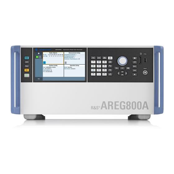
2. Disconnect the R&S AREG800A from the power source. 3.2 Instrument tour This chapter explains the control elements and the connectors of the R&S AREG800A. The views of the front panel and the rear panel help you to get familiar with the instru- ment and to perform first steps. - Page 29 ® Getting started R&S AREG800A Instrument tour Figure 3-2: R&S AREG800A front panel controls and connectors Utility keys, page 30 Touchscreen, page 29 Function keys, page 31 Keypad, page 31 Navigation controls, page 32 Display keys, page 33 SD card slot, page 33...
- Page 30 376, for cleaning the touchscreen. 3.2.1.2 Keys Utility keys The utility keys cause the R&S AREG800A to return to a defined instrument state and provide information on the instrument and assistance. Table 3-4: Utility keys Utility key Assigned functions...
- Page 31 ® Getting started R&S AREG800A Instrument tour Utility key Assigned functions [Setup] Accesses the general instrument settings [Help] Displays context-sensitive help text On/Standby The [On/Standby] key switches the instrument from the standby to the ready state or vice versa. The LED above the [On/Standby] key indicates the instrument state, see Chap- ter 3.1.13, "Switching on or...
- Page 32 ® Getting started R&S AREG800A Instrument tour Navigation controls The navigation controls include a rotary knob, navigation keys, and the display keys. They allow you to navigate within the display or within dialog boxes. Rotary knob The rotary knob has several functions: ●...
- Page 33 Adds a parameter to the user menu for quick access. 3.2.1.3 Connectors Various interface connectors are on the front panel of the R&S AREG800A. SD card slot SD card slot. Female USB (universal serial bus) 2.0 connector of type A, to connect devices like external USB devices, a mouse or a keyboard for enhanced operation.
-
Page 34: Rear Panel Tour
® series B connector. A power sensor is connected to the R&S AREG800A by inserting the male connector. To disconnect, pull the connector by its sleeve. You cannot disconnect the sensor sim- ply by pulling at the cable or the rear part of the connector. - Page 35 ® Getting started R&S AREG800A Instrument tour 3.2.2.1 Control, synchronization and multi-purpose connectors Figure 3-5: Connectors for control, synchronization and multi-purpose signals Control, page 35 Real Time Control, page 35 System Control, page 35 Sync In, Sync Out, page 35...
- Page 36 General purpose interface bus (GPIB) interface for remote control of the instrument. The interface is in compliance with the standards IEC 625, IEEE 488 and SCPI. Use this interface to connect a computer for remote control of the R&S AREG800A. To set up the connection, use high-quality shielded cables. See "Cable selection and elec-...
- Page 37 ® Getting started R&S AREG800A Instrument tour RJ-45 connector to connect the R&S AREG800A to a LAN for remote control, remote operation, and data transfer. How to: Chapter 3.1.7, "Connecting to LAN", on page 21 Two female USB (universal serial bus) 3.0 connectors of type A. You can connect devi- ces like a keyboard, a mouse, a memory stick or the R&S NRP-Z4 cable for the R&S...
-
Page 38: Trying Out The Instrument
23 3.3 Trying out the instrument This chapter introduces the first steps with the R&S AREG800A. It shows how to oper- ate and configure the instrument using simple examples. The complete description of the functionality and its usage is given in the R&S AREG800A user manual. -
Page 39: Configuring Static Operation Setups
Select "Mode > Dynamic" for simulation of dynamic radar objects. 3. Specify the reference of the radar object: ● Select "Object Reference > Origin", if the R&S AREG800A is the object refer- ence. ● Select "Object Reference > Mapped Sensor", if a sensor is the object refer- ence. -
Page 40: Saving And Recalling Settings
® Getting started R&S AREG800A Trying out the instrument 3. Click "Apply" and "Ok". The bandwidth settings for an external frontend connected to board "A" are applied. For detailed information on operating setups including simulation of dynamic scenarios, Chapter 7, "Configuring the operation setup",... - Page 41 ® Getting started R&S AREG800A Trying out the instrument 4. Select the "Filename" input field, use the on-screen keyboard, and enter MyTest- Signal. 5. Click "Save". The file MyTestSignal.savrcltxt is stored in the default direc- tory /var/user/. To load saved instrument settings You can restore the settings to the instrument at any time using the settings file.
- Page 42 ® Getting started R&S AREG800A Trying out the instrument 5. Click "Recall". All instrument settings are restored and the display resembles Chapter 3.3.1, "Con- figuring static operation setups", on page 39, which shows the instrument display right before the settings were saved.
-
Page 43: Instrument Control
See also Chapter 8, "File and data management", on page 118. 3.4 Instrument control This chapter provides an overview on how to work with the R&S AREG800A. It covers the following topics: ● Possible ways to operate the instrument..............43 ●... -
Page 44: Means Of Manual Interaction
"Remote operation over VNC", on page 51. 3.4.2 Means of manual interaction For the manual interaction with the R&S AREG800A, you have several methods that you can use as an alternative to perform a task: ● Touchscreen: Touchscreen operation is the most direct way to interact. Almost all control ele- ments and actions on the screen are based on the standard operating system con- cept. -
Page 45: Understanding The Display Information
® Getting started R&S AREG800A Instrument control 3.4.3 Understanding the display information The home screen of the R&S AREG800A displays all main settings and generator states, divided into three main operation areas. ● Additional display characteristics................45 3.4.3.1 Additional display characteristics... -
Page 46: Accessing The Functionality
® Getting started R&S AREG800A Instrument control 3.4.4 Accessing the functionality All functionalities are provided in dialog boxes as known from computer programs. You can control the instrument intuitively with the touchscreen. This section provides an overview of the accessing methods. -
Page 47: Entering Data
® Getting started R&S AREG800A Instrument control To minimize a dialog box ► To return to the home screen, tap the "Home" button. To close a dialog box To close a dialog box, you have the same controls as you know from computers or devices with touchscreen. - Page 48 The unit is added to the entry. Tip: For quick unit change, you can enter shortcuts, e.g. for a frequency value 1e8h for 100 MHz. For an overview of shortcuts supported by the R&S AREG800A, see Chapter B, "Unit shortcuts", on page 387.
-
Page 49: Getting Information And Help
® R&S AREG800A Getting started Instrument control "Redo" restores a previously undone action. 3.4.6 Getting information and help In some dialog boxes, graphics are included to explain the way a setting works. For further information, you can use the following sources: ●... -
Page 50: Remote Control
The corresponding help topic is displayed. 3.4.7 Remote control In addition to working with the R&S AREG800A interactively, located directly at the instrument, it is also possible to operate and control it from a remote PC. The R&S AREG800A supports various methods for remote control: ●... -
Page 51: Remote Operation Over Vnc
Thus, remote operation of the instrument is possible. Instrument control from a remote computer To access the basic utility functions of the R&S AREG800A, perform a right mouse click the block diagram and select "Key Emulation". A key panel to the right of the block diagram gives access to the utility functions provi- ded by the front panel keys. -
Page 52: Required Options
R&S AREG800A 4 Required options The basic equipment layout for generating radar signals includes R&S AREG800A base unit (R&S AREG8-B9) including one IF path. Extensions to the base unit require installation of further options. Extend the R&S AREG800A as follows: ●... - Page 53 ® Required options R&S AREG800A For more information, see data sheet. User Manual 1179.3615.02 ─ 01...
-
Page 54: Configuring Radar Objects
About radar echo generation The R&S AREG800A generates up to four radar echo signals by delaying the received radar signal through up to four optical fixed delay lines. The delays are fixed and defined during the purchasing process. - Page 55 / (4π) * R * 1/Att * 1/Att , where: ● : Gain of the R&S AREG800A transmit antenna, converted from dB to linear scale ● : Gain of the R&S AREG800A receive antenna, converted from dB to linear scale ●...
-
Page 56: Radar Objects Tile
® Configuring radar objects R&S AREG800A Radar Objects tile ● is the frequency of the RF output signal ● c = 299700000 m/s is the speed of light in the air. Either R&S AREG8-K799 or R&S AREG8-B60 can be installed. -
Page 57: Objects Settings
® Configuring radar objects R&S AREG800A Objects settings ● Configure units of radar object parameters. ● Visualize simulated radar objects, connected frontends and connected sensors. 5.2 Objects settings Access: ► Select "Radar Objects > Configuration". The "Objects" dialog opens and contains up to eight tabs for configuration of up to eight channels, one tab per channel. - Page 58 Chapter 5.5, "Units settings", on page 65. Object ← Object table Displays the number of the simulated radar object. If fully equipped, the R&S AREG800A can simulate up to eight radar objects "1" to "8". Table 4-2. User Manual 1179.3615.02 ─ 01...
- Page 59 ® Configuring radar objects R&S AREG800A Objects settings State ← Object table Activates simulation of the radar object. Remote command: on page 314 [:SOURce<hw>]:AREGenerator:OBJect<ch>[:STATe] on page 314 [:SOURce<hw>]:AREGenerator:OBJect:ALL[:STATe] Range ← Object table Sets the range of the simulated radar object.
-
Page 60: Scenario Settings
® Configuring radar objects R&S AREG800A Scenario settings 5.3 Scenario settings The "Scenario" dialog allows you to load and play files to simulate dynamic radar sce- narios. Access: 1. In the "Operation Setup" tile, select the following: a) Select "Mode > Dynamic". - Page 61 ® Configuring radar objects R&S AREG800A Scenario settings Remote command: on page 320 [:SOURce<hw>]:AREGenerator:SCENario:PROGress on page 321 [:SOURce<hw>]:AREGenerator:SCENario:STATus Select File Provides access to the standard "File Select" function of the instrument. The provided navigation possibilities in the dialog are self-explanatory.
-
Page 62: Logging Settings
® Configuring radar objects R&S AREG800A Logging settings "Loop" Files are played continuously within the defined positions in the file. Remote command: on page 320 [:SOURce<hw>]:AREGenerator:SCENario:REPLay[:MODE] Reset Resets "Start/Stop/Position Player" parameters. Remote command: on page 320 [:SOURce<hw>]:AREGenerator:SCENario:RESet Play Plays the selected file. -
Page 63: Logging Configuration Settings
® Configuring radar objects R&S AREG800A Logging settings Settings: ● Logging Configuration settings................63 ● Logging results......................64 5.4.1 Logging Configuration settings Access: ► Select "Radar Objects > Logging > Logging Config". The "Logging Config" tab provides settings to activate logging and to configure the scope and the time base of logged data. -
Page 64: Logging Results
® Configuring radar objects R&S AREG800A Logging settings 5.4.2 Logging results Access: ► Select "Radar Objects > Logging > Logging". The "Logging Config" tab provides settings to activate logging and to configure the scope and the time base of logged data. -
Page 65: Units Settings
® Configuring radar objects R&S AREG800A Units settings Displayed are up to 100 counts for each type. Remote command: on page 322 [:SOURce<hw>]:AREGenerator:DLOGging:NERRor? on page 323 [:SOURce<hw>]:AREGenerator:DLOGging:NWARning? on page 323 [:SOURce<hw>]:AREGenerator:DLOGging:NINFo? Clear Removes all logging information from the logging table. Also, the function resets the counts for each type of logged data. - Page 66 ® Configuring radar objects R&S AREG800A Units settings Settings: Range Unit........................66 Unit........................66 Horizontal Angle Unit....................66 Doppler Format......................66 Doppler Speed Unit.......................66 Doppler Shift Unit......................66 Range Unit Sets the unit of the range of the simulated radar object.
-
Page 67: Radar Power Settings
® Configuring radar objects R&S AREG800A Radar Power settings 5.6 Radar Power settings Access: ► Select one of the following: ● In the taskbar, select the "Radar Power" button. ● In the tile diagram, select "Radar Objects > Radar Power". -
Page 68: Overview Settings
® Configuring radar objects R&S AREG800A Overview settings 5.7 Overview settings Access: ► Select "Radar Objects > Overview". The "Overview" dialog provides an overview of all objects within the radar object simulation scenario. Also it provides detailed information on valid and invalid radar objects. -
Page 69: Valid Objects/Invalid Objects
Overview settings Polar coordinates map 1 = Valid radar objects 2 = Invalid radar objects 3 = Frontends connected to the R&S AREG800A 4 = Sensors connected to the R&S AREG800A 5.7.2 Valid Objects/Invalid Objects Access: ► Select "Radar Objects > Overview > Valid Objects/Invalid Objects". - Page 70 ® Configuring radar objects R&S AREG800A Overview settings ● Attenuation, see "Attenuation" on page 59 ● Doppler speed or Doppler shift, see "Doppler Speed" on page 59 or "Doppler Shift" on page 59. ● Horizontal angle, see "Horizontal Angle" on page 59.
-
Page 71: Configuring The Measurement Setup
A typical measurement setup consists of the R&S AREG800A base unit with connec- ted frontend. The R&S AREG800A receives a radar signal from the RUT (radar under test) in the specified frequency band (e.g. 24 GHz or 77 GHz). It downconverts the signal to the intermediate frequency (IF). -
Page 72: Frontend Configuration
Preset Behavior On Activates, if the R&S AREG800A acts as after an instrument preset or not. If activated ("Preset Behavior On > On", the R&S AREG800A presets all parameters in the "Radar Object" tile. Activation does not affect configurations and connection set- tings of connected external frontends. -
Page 73: General Settings
® Configuring the measurement setup R&S AREG800A Frontend configuration The side-tab provides settings to configure connected external frontends, e.g. an R&S QAT100. Also, you can configure individual characteristics of up to eight connec- ted frontends. Each connected frontend has a dedicated configuration in the corre- sponding side tab. - Page 74 QAT........................75 Show Connector......................75 Displays the identification name of the connected frontend. R&S QAT100, e.g. "Q1" for the first connected R&S QAT100. You can connect up to eight R&S QAT100 to the R&S AREG800A. Remote command: on page 333 [:SOURce<hw>]:AREGenerator:FRONtend:TRX<ch>|QAT<ch>:ID Alias Sets the alias of the frontend.
-
Page 75: Trx Settings
® Configuring the measurement setup R&S AREG800A Frontend configuration Type Displays the type of the connected frontend, that is "QAT". Remote command: [:SOURce<hw>]:AREGenerator:FRONtend:TRX<ch>|QAT<ch>:TYPE on page 334 Remove QAT Removes the configuration of the connected frontend. Also, the corresponding side tab labelled "QAT" "ID = Qx" is removed to the right of the dialog. - Page 76 ® Configuring the measurement setup R&S AREG800A Frontend configuration Each "TRX" side-tab provides the following settings, that are individual for each con- nected TRX-type frontend: ● Physical settings of the radar signal path between frontend and radar sensor ● Connection settings of the R&S QAT100 ●...
-
Page 77: Angle Frontend To Sensor
AREG Antenna Gain TX Displays the antenna gain of transmitting antenna (TX) that is mounted at the R&S AREG800A. Configuring a custom gain value, requires "Use Custom Antenna > On". Set the result- ing total TX antenna gain according to your antenna assembly mounted at the R&S AREG800A. -
Page 78: Qat Settings
Frontend Bandwidth Displays the frequency bandwidth of the output signal of the connected frontend, e.g. an R&S QAT100. The frequency bandwidth depends on the configuration of the R&S AREG800A and the configuration of the connected frontend. Remote command: on page 332 [:SOURce<hw>]:AREGenerator:FRONtend:TRX<ch>|QAT<ch>:BW... - Page 79 ® Configuring the measurement setup R&S AREG800A Frontend configuration Each "QAT" side-tab provides the following settings, that are individual for each con- nected R&S QAT100: ● Physical settings of the radar signal path between frontend and radar sensor ● Connection settings of the R&S QAT100 ●...
- Page 80 330 [:SOURce<hw>]:AREGenerator:FRONtend:QAT<ch>:HOSTname on page 330 [:SOURce<hw>]:AREGenerator:FRONtend:QAT<ch>:IPADdress Connect Triggers a connection procedure to connect the R&S AREG800A with the external frontend in the network. Also, the connection status is displayed as a message and via the icon on the side- tab.
- Page 81 Frontend Bandwidth Displays the frequency bandwidth of the output signal of the connected frontend, e.g. an R&S QAT100. The frequency bandwidth depends on the configuration of the R&S AREG800A and the configuration of the connected frontend. Remote command: on page 332 [:SOURce<hw>]:AREGenerator:FRONtend:TRX<ch>|QAT<ch>:BW...
-
Page 82: Cable Correction Settings
® Configuring the measurement setup R&S AREG800A Frontend configuration 6.2.4 Cable correction settings Access: ► Specify the cable correction for the connected external frontend: ● For TRX-type frontends, select "TRX > Cable Correction" ● For QAT-type frontends, select "QAT > Cable Correction"... - Page 83 ® Configuring the measurement setup R&S AREG800A Frontend configuration Configure cable correction settings for two or eight channels in Rx direction and in Tx direction. To set the number of QAT channels, see "QAT Channel Mode" on page 80. Cable correction values for Tx direction and Rx direction are configured in a table, see "Cable correction table"...
-
Page 84: Sensor Configuration
Settings: ● Overview......................... 84 ● Sensor settings....................... 86 6.3.1 Overview Access: ► Select "Measurement Setup > Configuration > Sensor Config > Overview". The "Overview" side-tab provides a list of sensors connected to the R&S AREG800A. User Manual 1179.3615.02 ─ 01... - Page 85 Remove Sensor......................85 Sensor........................86 Displays the identification name of the connected sensor, e.g. "S1" for the first connec- ted sensor. You can connect up to eight sensors to the R&S AREG800A. Remote command: on page 336 [:SOURce<hw>]:AREGenerator:SENSor<ch>:ID Alias Sets the alias of the sensor.
-
Page 86: Sensor Settings
® Configuring the measurement setup R&S AREG800A Sensor configuration Add Sensor Adds a configuration for a connected sensor. A line with contiguous numeration is added below the already listed sensors. "Alias > Sensor" is assigned automatically. Also, a new side tab labelled "Sensor" "ID = Sx"... -
Page 87: Channel Configuration
6.4.1 Overview Access: ► Select "Measurement Setup > Configuration > Channel Config > Overview". The "Overview" side-tab provides a list of eight channels of the R&S AREG800A. You can configure the state and alias for eight channels individually. Settings: ID...........................87 State..........................88... -
Page 88: Channel Settings
® Configuring the measurement setup R&S AREG800A Channel configuration Displayed are eight radar channels that are designated "A1" to "D2". For details, see "Channel x" on page 57. Remote command: on page 325 [:SOURce<hw>]:AREGenerator:CHANnel:ID? State Activates the radar channel. Remote command: on page 326 [:SOURce<hw>]:AREGenerator:CHANnel[:STATe]... -
Page 89: Channel Mapping
® Configuring the measurement setup R&S AREG800A Channel mapping For information on the I/Q modulation performance in any of the modes, see the data sheet. "Fast" Fast optimization by compensation for I/Q skew. This mode is suitable in time sensitive environments and narrowband signal. -
Page 90: Channel Mapping Settings
® Configuring the measurement setup R&S AREG800A Channel mapping Settings: 6.5.1 Channel Mapping settings.....................90 6.5.2 Adjust Level settings..................... 92 6.5.1 Channel Mapping settings Access: ► Select "Measurement Setup > Configuration > Channel Mapping". The "Channel Mapping" tab of the "Measurement Setup" dialog opens. - Page 91 ® Configuring the measurement setup R&S AREG800A Channel mapping Displayed are channel ID and channel name for each radar channel. You can check the location of the output connectors of the radar channel by clicking "Show Connec- tor". Also, you can select the mapping frontend and the mapping sensor, adjust levels of each radar channel individually or adjust all radar channel levels at the same time.
-
Page 92: Adjust Level Settings
[:SOURce<hw>]:AREGenerator:MAPPing<ch>:ADJust:LEVel:OTIMe on page 327 6.6 Reference oscillator The R&S AREG800A is equipped with an internal reference oscillator that generates a reference frequency of 10 MHz. It is used as internal reference source for the synthe- sizer. Alternatively, you can apply an external reference signal with reference frequency of 3.2 GHz. -
Page 93: Required Options
Configuring the measurement setup R&S AREG800A Reference oscillator 6.6.1 Required options R&S AREG800A base unit For more information, see data sheet. 6.6.2 Reference frequency settings Access: 1. Select "Measurement Setup" > "Reference Frequency". In the "Reference Frequency" tab, you can select the reference frequency signal source and the frequency and synchronization bandwidth mode of an external ref- erence signal. - Page 94 Adjustment Value. "External" Uses an external reference signal. Note: If the external reference is missing, the R&S AREG800A issues a warning message and indicates the icon (external refer- ence missing). To set the frequency of the external reference, see "External Refer-...
-
Page 95: Reference Output Settings
PLL. The R&S AREG800A issues an error message. For more information, see data sheet. Remote command:... -
Page 96: Adjustment Settings
® Configuring the measurement setup R&S AREG800A Reference oscillator 2. Select "Reference Output". In the "Reference Output" tab, you can set the reference frequency value at the output connectors. As a result of parameter dependencies, "Preset This Parameter" sometimes does not affect output dialogs. -
Page 97: Using Power Sensors
[:SOURce]:ROSCillator[:INTernal]:ADJust:VALue 6.7 Using power sensors The R&S AREG800A works with most of the R&S NRP power sensors and thus sup- ports various application tasks. Using power sensors, you can for example determine attenuation characteristics of downstream equipment or cables. You can use the mea- sured values to compensate the losses with internal control functions or with an exter- nal control circuit in real time. -
Page 98: Connecting R&S Nrp Power Sensors To The R&S Areg800A
R&S AREG800A Using power sensors 6.7.1 Connecting R&S NRP power sensors to the R&S AREG800A R&S NRP sensors are connected to the R&S AREG800A in the following ways: ● Connection to the Sensor connector – R&S NRP-ZK6 (six-pole interface cable) for R&S NRPxx power sensors –... -
Page 99: Nrp Sensor Mapping
AREG800A Using power sensors On connection, the R&S AREG800A immediately starts the measurement of a detec- ted R&S NRP power sensor. If you perform an instrument preset ([Preset] key or *RST), the R&S AREG800A stops the measurements. The connection and the map- ping of the power sensors remain, the measurements must be restarted. - Page 100 Shows or hides the "Add Sensor" settings. Add Sensor settings Configures settings to add sensors connected to the R&S AREG800A via USB or LAN. Add LAN Sensor settings ← Add Sensor settings Configures settings to add sensors connected to the R&S AREG800A via LAN.
-
Page 101: Nrp Power Viewer
348 :SLISt:SCAN:LSENsor Add USB Sensor settings ← Add Sensor settings Configures settings to add sensors connected to the R&S AREG800A via USB. "Device ID or Sensor Name" Displays the device identifier or the name of the R&S NRP power sensor. - Page 102 ® Configuring the measurement setup R&S AREG800A Using power sensors Measurements are continuously repeated in a predefined time window. The measure- ment result is obtained by averaging the measured values for the last 2N time win- dows. This approach is referred as a two-step averaging process.
- Page 103 ® Configuring the measurement setup R&S AREG800A Using power sensors ● After a substantial change of the ambient temperature ● After fastening the power sensor module to an RF connector at high temperature ● After several hours of operation ●...
- Page 104 ® Configuring the measurement setup R&S AREG800A Using power sensors The "Overview" tab shows the list of detected sensors, and provides a separate tab per sensor. A sensor tab contains all parameters for configuring the sensor settings, like aver- age or peak display, reference source, filter and level offset.
- Page 105 ® Configuring the measurement setup R&S AREG800A Using power sensors └ Display....................106 └ Use Frequency Of..................106 └ Frequency..................... 106 └ Level Offset State,Level Offset..............106 └ Filter......................107 └ Filter Length....................107 └ Noise/Signal Ratio..................107 └ Auto Once..................... 107 └...
- Page 106 If you have a frequency converting device between the generator and the DUT. If the frequency converter doubles the frequency, you can set twice the frequency in the R&S AREG800A. The R&S power sen- sor considers this RF frequency setting.
- Page 107 ® Configuring the measurement setup R&S AREG800A Using power sensors Remote command: on page 356 :SENSe<ch>[:POWer]:OFFSet on page 356 :SENSe<ch>[:POWer]:OFFSet:STATe Filter ← Sensor settings Selects the way the length of the used filter is defined. See also "About the measuring principle, averaging filter, filter length, and achieving stable results"...
- Page 108 ® Configuring the measurement setup R&S AREG800A Using power sensors See also "About the measuring principle, averaging filter, filter length, and achieving stable results" on page 101. Remote command: on page 354 :SENSe<ch>[:POWer]:FILTer:SONCe Timeout ← Sensor settings For "Filter > Fixed Noise", sets a time limit for the averaging process.
- Page 109 ® Configuring the measurement setup R&S AREG800A Using power sensors Check the used disc space regularly and remove log files to maintain storage capacity. Note: The logging function is intended for measurements with long time intervals. It is suitable source for data reconstructions if the connection to the sensor was interrupted.
-
Page 110: Configuring The Operation Setup
® Configuring the operation setup R&S AREG800A Operation Setup tile 7 Configuring the operation setup A typical operation setup consists of the R&S AREG800A base unit with connected frontend. ● Operation Setup tile....................110 ● Operation Setup settings..................111 ● Bandwidth Configuration settings................113... -
Page 111: Operation Setup Settings
® Configuring the operation setup R&S AREG800A Operation Setup settings 7.2 Operation Setup settings Access: ► Select "Operation Setup > Operation Setup". The "Operation Setup" tab of the "Operation Setup" dialog opens. Settings: Mode..........................111 Object Reference......................111 Data Source.........................112 HiL - Protocol.......................112... - Page 112 ® Configuring the operation setup R&S AREG800A Operation Setup settings "Origin" Sets the object reference to "Origin". "Mapped Sen- Sets a mapped sensor as object reference, see Chapter 6.3.1, "Over- view", on page 84. sor" Remote command: on page 338 [:SOURce<hw>]:AREGenerator:OSETup:REFerence...
-
Page 113: Bandwidth Configuration Settings
® Configuring the operation setup R&S AREG800A Bandwidth Configuration settings Remote command: on page 337 [:SOURce<hw>]:AREGenerator:OSETup:APPLy Applies the current operation setup configuration and exits the dialog. Remote command: on page 337 [:SOURce<hw>]:AREGenerator:OSETup:APPLy 7.3 Bandwidth Configuration settings Access: ► Select "Operation Setup > Bandwidth Config". -
Page 114: Realtime Control Network Settings
® Configuring the operation setup R&S AREG800A Realtime Control Network settings "Apply" Applies the settings of the current bandwidth configuration. "Ok" Applies the settings of the current bandwidth configuration and exits the dialog. Remote command: on page 337 [:SOURce<hw>]:AREGenerator:OSETup:BW:APPLy 7.4 Realtime Control Network settings Access: ►... - Page 115 ® Configuring the operation setup R&S AREG800A Realtime Control Network settings Restart Network Terminates the network connection of the instrument and sets it up again. You can use this function to fix network problems. Remote command: on page 306 :SYSTem:COMMunicate:RT:NETWork:RESTart...
-
Page 116: System Control Network Settings
® Configuring the operation setup R&S AREG800A System Control Network settings Remote command: n.a. 7.5 System Control Network settings Access: ► Select "Operation Setup > System Control Network". The "System Control Network" tab of the "Operation Setup" dialog opens. Settings: Network Status...................... - Page 117 ® Configuring the operation setup R&S AREG800A System Control Network settings Remote command: on page 306 :SYSTem:COMMunicate:RT:NETWork:RESTart on page 309 :SYSTem:COMMunicate:SYST:NETWork:RESTart Hostname Displays the hostname of the instrument connected to the network. Remote command: on page 306 :SYSTem:COMMunicate:RT:NETWork[:COMMon]:HOSTname on page 309...
-
Page 118: File And Data Management
Due to security reasons, system files and the system directory are protected and there- fore not accessible. The scope of this section is only the files with user data. This section is an overview of the R&S AREG800A file system and covers the following topics: ●... - Page 119 ● Temporary, i.e. volatile data that the instrument retains while it is powered on. Volatile data is immediately lost when the R&S AREG800A is switched off. File storage location Both, the user directory /var/user/ on the internal memory or the /usb/ directory on the memory stick, can be used to preserve user-defined data.
-
Page 120: Restoring The (Default) Instrument Configuration
The R&S AREG800A has various options to set default settings. You can preset the R&S AREG800A to an initial state at any time as a known starting point for configura- tions. It is often useful as a first step in troubleshooting when unusual results arise. - Page 121 ® File and data management R&S AREG800A Restoring the (default) instrument configuration Preset executes a defined instrument setup to provide an initial instrument state as a basis for a new configuration. It resets all parameters and switching states, including also the states of inactive operating modes.
-
Page 122: Preset, Set To Default And Factory Preset Settings
128) Mark / Do not mark parameters changed from preset To survey the current state of the settings concerning default values, the R&S AREG800A offers a feature that visually identifies deviations from the default val- ues. For more information, see Chapter 8.2.2, "How to identify parameters which are not in... -
Page 123: How To Identify Parameters Which Are Not In A Preset State
To activate this display: 1. Open the context-sensitive menu (touch and hold the screen anywhere in the GUI of the R&S AREG800A). 2. Select "Mark all parameters changed from preset". If enabled, the corresponding settings are marked. 8.2.3 How to recall user settings automatically after preset You can define the settings that are restored when you preset the instrument. -
Page 124: Protecting Data
Security settings are never reset. Resets all parameters and switching states, and closes all opened dialogs. 8.3 Protecting data During operation, the R&S AREG800A saves user data permanently in the user direc- tory, see "File storage location" on page 119. -
Page 125: Saving And Recalling Instrument Settings
Or, in a test setup with more than one signal gen- erator, you want to transfer the used settings to another R&S AREG800A. In these cases, you can save and recall instrument and user settings, and possibly other related data. -
Page 126: Save/Recall Settings
® File and data management R&S AREG800A Saving and recalling instrument settings 8.4.1 Save/recall settings To access the dialog for storing and loading the complete instrument settings 1. Select "System Config > Save/Recall". 2. Select "Operation Mode > Save or Recall" to access the corresponding settings. - Page 127 274 :MMEMory:CATalog? Recent files Displays the files last used. Show SCPI List Opens the "SCPI List", which lists the current settings of the R&S AREG800A as SCPI commands. The R&S AREG800A provides this function for Operation Mode > SCPI-Export.
-
Page 128: How To Save And Recall Instrument Settings
® File and data management R&S AREG800A Saving and recalling instrument settings During recall, the instrument considers all related settings, for example sweeps in active state or lists. An error message indicates the settings which cannot be imple- mented. Remote command:... -
Page 129: Exporting And Importing Remote Command Lists
The R&S AREG800A also offers a SCPI macro recorder with code generator that is used to record manual settings and create an executable script, see Chapter 10.9.4,... -
Page 130: File Manager Settings
The "File Manager" dialog provides all standard functions required for file manage- ment. It displays the contents of the selected folder on the R&S AREG800A and provides functions to rename, delete, copy, or move individual files. 8.6.1 File manager settings Access: ►... -
Page 131: Map Network Share Settings
® File and data management R&S AREG800A Using the file manager Directory and Filename Selects the directory in which the file to be deleted or copied is located. The dialog lists all files in this directory. Selected files are highlighted. The path is indicated above the directory tree. -
Page 132: How To Display All Saved Files
® File and data management R&S AREG800A Using the file manager Password........................132 Reconnect at Startup....................132 Connect........................132 Change........................132 Disconnect........................132 Network Folder Enter the path of the folder or computer, e.g. //<IP Address>/user or //<server name>/user. Local Folder Enter a letter or an alias name to describe the folder. -
Page 133: How To Map A Network Folder
R&S AREG800A, distribute waveform files to several instruments or you have to access frequently the same network drive. In these cases, on a R&S AREG800A con- nected to a LAN you can create a shortcut to this network folder or this computer. -
Page 134: How To Transfer Files From And To The Instrument
Mainly because of security reasons, the access to the file system of your R&S AREG800A can be denied, because one or all these access methods are deliber- ately disabled. Access to the file system via LAN and/or USB requires that the corre- sponding service is enabled and a write access to the file system is enabled. - Page 135 Chapter 9.4, "Using the security settings", on page 159. The R&S AREG800A requests a reboot. 5. Confirm the request. The system reboots. The enabled settings are active. To enable file transfer over FTP 1. Select "System Config > Setup > Security > Security > LAN Services".
-
Page 136: Accessing The File System Of The R&S Areg800A Via Ftp
8.7.2 Accessing the file system of the R&S AREG800A via FTP If the R&S AREG800A is connected to a LAN, you can use file transfer protocol (FTP) to access the file system and to transfer files from and to the instrument. -
Page 137: Accessing The R&S Areg800A File System Via Smb (Samba)
The user directory corresponds to the /var/user/ directory of the instrument; the volatile directory - to the /var/volatile directory. To map the R&S AREG800A as a network drive to the remote PC We assume that the instrument and the remote PC are connected to a LAN. -
Page 138: Using A Usb Storage Device For File Transfer
In the "Folder" field, enter //<"IP Address" of the Instrument>/user or //<"Hostname" of the Instrument>/user For example: //10.124.0.166/user or //AREG800A-102030/user. Tip: The R&S AREG800A indicates its IP address on the screen. c) Select "Finish". A log-on dialog opens and requests a user name and a password. -
Page 139: Using A File Server For Test Files Exchange
133. 2. On each R&S AREG800A, use the same alias name for the directory of the file server, i.e. enter the same "Local Folder" (in this example Setups). On any of the R&S AREG800A, you access the file server directly from the "File Manager"... -
Page 140: Hardcopy Settings
® File and data management R&S AREG800A Creating screenshots of current settings 8.8.1 Hardcopy settings Access: ► Select "System Config > Setup > User Interface > Hardcopy". The remote commands required to define these settings are described in Chapter 11.8, "HCOPy... - Page 141 ® File and data management R&S AREG800A Creating screenshots of current settings If you have enabled "Automatic Naming", the instrument displays the automatically generated filename. Remote command: on page 266 :HCOPy:FILE[:NAME] Format Selects the output file format, for example *.bmp, *.jpg*.xpm and *.png.
-
Page 142: How To Save A Hardcopy Of The Display
® File and data management R&S AREG800A Creating screenshots of current settings Note: To select the destination path, specify also a filename. Otherwise an error mes- sage is displayed and selection is canceled. Remote command: on page 267 :HCOPy:FILE[:NAME]:AUTO:DIRectory Clear Path ← Hardcopy Options > Automatic Naming Deletes all image files with extensions *.bmp, *.jpg, *.png and *.xmp in the direc-... - Page 143 ® File and data management R&S AREG800A Creating screenshots of current settings 2. To define the output format, select "Format > JPG". 3. To enable the instrument to create output filenames, select "Automatic Naming > On". 4. Select "Options...". 5. In the "Hardcopy Options" dialog: a) To change the default directory the file is saved in, select "Automatic Naming...
-
Page 144: General Instrument Functions
[User] as quick access for later retrieval. ● Chapter 9.3, "Managing licenses and license keys", on page 152 If you have purchased an additional option for the R&S AREG800A, you can enable it using a license key. ● Chapter 8.2, "Restoring the (default) instrument configuration",... -
Page 145: Display And Keyboard Settings
® General instrument functions R&S AREG800A Customizing the user interface 9.1.1 Display and keyboard settings Access: 1. Select "System Config > Setup > User Interface > Display/Keyboard > Display". 2. Select "Display/Keyboard > USB Keyboard". In the "Display/Keyboard" dialog, you can change regional and language options for the GUI and an external keyboard, and define the screen saver settings. -
Page 146: Display Update Settings
® General instrument functions R&S AREG800A Customizing the user interface Display Adjusts the brightness of the display. Increase the value to turn up the display brightness. Remote command: on page 260 :DISPlay:BRIGhtness RF Hardkey Adjusts the brightness of the [RF On/Off] key. -
Page 147: How To Set The Initial Instrument Settings
AREG800A Customizing the user interface 9.1.3 How to set the initial instrument settings This section describes how to set up the R&S AREG800A initially. 9.1.3.1 Setting the keyboard language You can select the language of the external keyboard connected to the instrument. -
Page 148: Organizing Frequently Used Settings As Favorites
2. Select "User Interface > Display" 3. Disable the "Screen Saver" state. 9.2 Organizing frequently used settings as favorites The R&S AREG800A provides two possibilities to define frequently used settings and procedures for later retrieval individually. User menu and [User] key These two functions work similar to the favorites function of a browser or other pro- grams. -
Page 149: User Menu Settings
Save/Recall vs. recall setup If you need to restore a specific signal generation setup and perform further configura- tions based on this particular instrument state, the R&S AREG800A provides two options: ●... - Page 150 1. Create the favorites list, as described in "Creating a "User Menu"" on page 150. 2. Save the favorites list. 3. To tansfer a file from or to an instrument, the R&S AREG800A provides several options, see "File handling" on page 119.
-
Page 151: Define User Key Actions Settings
® General instrument functions R&S AREG800A Organizing frequently used settings as favorites 9.2.3 Define user key actions settings Access: ► Select "System Configuration > Setup > User Interface > Define User Key". The dialog displays a list of the currently enabled actions and provides functions to define new, edit or remove existing actions. -
Page 152: How To Assign Actions To The [User] Key
In the list of actions ("Select Action to Execute" dialog), navigate to the required action. The R&S AREG800A executes the action and opens the dialog. 9.3 Managing licenses and license keys An option is ready to operate after it is enabled with a license keycode supplied with the option. -
Page 153: Manage License Keys Settings
® General instrument functions R&S AREG800A Managing licenses and license keys 9.3.1 Manage license keys settings The "Manage Licnese Keys" dialog provides all information on the available licenses. Instrument-related steps guide you through the process of registering or deactivating licenses. - Page 154 ® General instrument functions R&S AREG800A Managing licenses and license keys This tab lists all active options, with information on the available number of an option, the license type and registration. You can query inactive or disabled options also. 3. Select "Open License Server".
-
Page 155: Using The License Server
As a browser application you can access the R&S License Server either in a browser and also directly in the R&S AREG800A. The onboard license server integrated in the instrument firmware has connection to a local smartcard memory. The local smartcard holds local licenses, i.e. - Page 156 ® General instrument functions R&S AREG800A Managing licenses and license keys As opposed to local licenses, the application also manages licenses referred to as floating licenses. For managing floating licenses, the same license server application runs on a PC at customer's site.
- Page 157 2. Select "Open License Server". The license server browser opens. The application shows the internal license server of the R&S AREG800A in the "License providers" tile. The "License", "Ana- lytics" and "Configuration" views enable you to activate licenses, or, e.g., deacti- vate and release licenses again.
-
Page 158: How To Move A Portable License
® General instrument functions R&S AREG800A Managing licenses and license keys 9.3.3 How to move a portable license This example is intended to explain how to perform the required steps at the instru- ment. Use a USB flash drive to transfer the license key files between the instruments and the browser. -
Page 159: Using The Security Settings
13. Select the created license key file. The portable option is installed on the target instrument. 9.4 Using the security settings The protection function of the R&S AREG800A offers several levels to activate particu- lar functions like self-test or tests for service purposes specifically. Protection The five protection levels are automatically active on startup, the protection levels, that means all protected functions are locked. -
Page 160: Protection Level Settings
Protection level 3 to 5 Are reserved for internal use. Security The security concept of the R&S AREG800A helps you to protect your instrument against uncontrolled access and changes. All provided security services require that you enter the security password. -
Page 161: Setting Security Parameters
® General instrument functions R&S AREG800A Using the security settings The "Protection" dialog provides access to the unlocking of different protection lev- els. Several functions in the instrument are password-protected to prevent for example accidental changes, "Protection" on page 159. - Page 162 ® General instrument functions R&S AREG800A Using the security settings In the "General" tab, you can determine the security level for firmware updates, and configure the security settings for the mass memory and manual operation. All modified settings in this dialog are not applied until you enter the Security Password and confirm with Accept.
- Page 163 159 for more information on the security concept. ● The release notes for details on signature verification when installing new or former firmware versions, available at www.rohde-schwarz.com/firmware/areg800a. "Confirm Unsigned" Performs the signature verification. If the check detects any discrepancies, the instrument issues a warn- ing message.
- Page 164 ® General instrument functions R&S AREG800A Using the security settings Note: Remove all USB memory devices before disabling the USB storage. If any USB memory device remains connected, disabling is blocked, and the instrument returns a warning message. Volatile Mode Activates volatile mode, so that no user data can be written on the internal memory permanently.
- Page 165 ® General instrument functions R&S AREG800A Using the security settings The "SW Update" tab enables you to lock front panel operation and/or reading the display. The remote commands available to control security settings are described in: ● Chapter 11.6, "DISPlay subsystem",...
- Page 166 ® General instrument functions R&S AREG800A Using the security settings "Touchscreen Off" Locks the touch sensitivity of the screen. This security feature protects the instrument against unintentional change of settings by accidentally touching of the screen. Still available controls for manual operation are: ●...
-
Page 167: Configuring Lan Services
® General instrument functions R&S AREG800A Using the security settings Enabling a locked user interface for manual operation Follow the instructions listed in "Unlocking (reactivating) the user interface for manual operation" on page 173. Remote command: on page 287 :SYSTem:ULOCk... - Page 168 "SMB (Samba)" Activates access to SMB (Server Message Block), used for providing shared access to files, printers and serial ports of a network. See also Chapter 8.7.3, "Accessing the R&S AREG800A file system via SMB (Samba)", on page 137. "Avahi (Zeroconf)"...
-
Page 169: Password Management
® General instrument functions R&S AREG800A Using the security settings ● "Changing the default security password" on page 172. Accept Applies the modified settings, provided the security password is entered and correct. 9.4.4 Password management Access: 1. Select "System Config > Setup > Security > Security > Password Management >... - Page 170 ® General instrument functions R&S AREG800A Using the security settings How to: ● "Changing the default user password of the instrument" on page 172. ● "Changing the default security password" on page 172. User Name Indicates the user name used for access to the Linux operating system and valid for VNC, FTP and SMB (Samba) access.
-
Page 171: How To Prevent Unauthorized Access
® General instrument functions R&S AREG800A Using the security settings Change Password ← User Password Changes the user password accordingly. Security Password Enables you to change and confirm the security password. Old Password ← Security Password Enters the currently used security password. The default password is '123456'. - Page 172 ® General instrument functions R&S AREG800A Using the security settings ● "Disabling LAN services" on page 173 ● "Activating SMB version 1.0/2.0 client and server" on page 173 ● "Disabling the frequency and level indication in the status bar" on page 173 ●...
- Page 173 ® General instrument functions R&S AREG800A Using the security settings Disabling LAN services 1. Select "System Config > Setup > Security > Security > LAN Services > Main Ser- vices". 2. Select, for example, "FTP > Off" or "VNC > Off".
-
Page 174: Undoing Or Restoring Actions
® General instrument functions R&S AREG800A Undoing or restoring actions a) On the instrument's keypad or external keyboard, press any key. The instrument prompts you to enter the security password for unlocking. If you press the character of the first key, the input field accepts the character immediately. -
Page 175: Shutting Down And Rebooting The Instrument
® General instrument functions R&S AREG800A Shutting down and rebooting the instrument State Enables the recording of the performed actions. History List Lists the performed actions, provided "Undo/Redo" state is "On". Clear History Deletes the recorded list of the performed steps. -
Page 176: Network Operation And Remote Control
(interfaces) for remote access. The following descriptions provide information required for operating the R&S AREG800A remotely. The information applies to all applications and operating modes supported by the instrument. Definitions specified in the SCPI standard are not provided. -
Page 177: Overview Of Remote Access Modes
● Clients supporting remote operation depend on the used remote device, see Table 10-1. ● How to: see Chapter 10.10, "Operating the R&S AREG800A remotely using VNC", on page 235. Table 10-1: Supported VNC operation modes Remote device VNC client... -
Page 178: Remote Control Interfaces And Protocols
® Network operation and remote control R&S AREG800A Remote control interfaces and protocols Remote device VNC client Requirements Characteristics ● Web browser with HTML5 Web sockets must be supported. Slower than the other modes. No additional installation or acti- vation required. -
Page 179: Lan Interface
I/O software library R&S VISA for download at the Rohde & Schwarz website http://www.rohde- schwarz.com/rsvisa. How to: Chapter 10.8, "Controlling the R&S AREG800A remotely", on page 215 describes how to configure the remote control interfaces. ● interface......................179 ●... - Page 180 ® Network operation and remote control R&S AREG800A Remote control interfaces and protocols TCPIP::<host address>[::<LAN device name>][::INSTR] TCPIP = designates the network protocol host address = designates the IP address or hostname of the instrument [::LAN device name] = defines the protocol and the instance number of a subinstrument...
-
Page 181: Usb Interface
® Network operation and remote control R&S AREG800A Remote control interfaces and protocols port = determines the used port number SOCKET = indicates the raw network socket resource class Socket communication requires the specification of the port (commonly referred to as port number) and of "SOCKET"... -
Page 182: Gpib Interface (Iec/Ieee Bus Interface)
ASRL1::INSTR 10.2.3 GPIB interface (IEC/IEEE bus interface) To control the R&S AREG800A over the GPIB bus, the instrument and the controller PC must be connected with a GPIB bus cable. A GPIB bus card, the card drivers and the program libraries for the used programming language must be installed on the con- troller. -
Page 183: Lxi Browser Interface
10.2.4 LXI browser interface The LXI browser interface allows easy configuration of the LAN and remote control of the R&S AREG800A without additional installation requirements. The instrument's LXI browser interface works correctly with all W3C compliant browsers. Chapter 10.11.1, "LXI functionality",... - Page 184 Remote control programs and libraries Example: Remote control (application) program using VISA Figure 10-3: Application program using VISA Protocol Remote control program Socket viOpen (..., "TCPIP:AREG800A-102030::5025::SOCKET", ...) viPrintf (..., "SOUR:FREQ 2GHz\n") VXI-11 viOpen (..., "TCPIP:AREG800A-102030::inst0::INSTR", ...) viPrintf (..., "SOUR:FREQ 2GHz\n") HiSLIP viOpen (..., "TCPIP:AREG800A-102030::hislip0::INSTR", ...)
- Page 185 Remote control programs and libraries Example: Remote control program using instrument driver (VISA available) Figure 10-4: Application using instrument driver (VISA available) Protocol Remote control program Socket rsareg8_init ("TCPIP:AREG800A-102030::5025::SOCKET", ...) rsareg8_SetFrequency (..., 2e9) VXI-11 rsareg8_init ("TCPIP:AREG800A-102030::inst0::INSTR", ...) rsareg8_SetFrequency (..., 2e9) HiSLIP rsareg8_init ("TCPIP:AREG800A-102030::hislip0::INSTR", ...)
-
Page 186: Status Reporting System
Example: Remote control program using instrument driver (VISA not available) Figure 10-5: Remote control program using instrument driver (VISA not available) Protocol Remote control program Socket rsareg8_init ("TCPIP:AREG800A-102030::5025::SOCKET", ...) rsareg8_SetFrequency (..., 2e9) GPIB rsareg8_init ("GPIB::28::INSTR", ...) rsareg8_SetFrequency (..., 2e9) 10.4 Status reporting system The status reporting system stores all information on the current operating state of the instrument, and on errors which have occurred. - Page 187 = Error- /Event-Queue 1, 0 = not used Note: This legend explains the abbreviations to the Status Byte Register. The R&S AREG800A uses the following status registers: ● Status Byte (STB) and Service Request Enable (SRE), see Chapter 10.4.3, "Sta- tus byte (STB) and service request enable register (SRE)",...
-
Page 188: Structure Of A Scpi Status Register
® Network operation and remote control R&S AREG800A Status reporting system ● Standard Event Status, i.e. the Event status Register (ESR) and the Event Status Enable (ESE), see Chapter 10.4.4, "Event status register (ESR) and event status enable register (ESE)", on page 191. - Page 189 ® Network operation and remote control R&S AREG800A Status reporting system Description of the five status register parts The five parts of a SCPI status register have different properties and functions: ● CONDition The CONDition part is written directly by the hardware or it mirrors the sum bit of the next lower register.
-
Page 190: Status Byte (Stb) And Service Request Enable Register (Sre)
® Network operation and remote control R&S AREG800A Status reporting system The instrument automatically generates the sum bit for each register. Thus an event can lead to a service request throughout all levels of the hierarchy. 10.4.3 Status byte (STB) and service request enable register (SRE) The STatus Byte (STB) is already defined in IEEE 488.2. -
Page 191: Event Status Register (Esr) And Event Status Enable Register (Ese)
® Network operation and remote control R&S AREG800A Status reporting system 10.4.4 Event status register (ESR) and event status enable register (ESE) The ESR is defined in IEEE 488.2. It can be compared with the EVENt part of a SCPI register. -
Page 192: Operation Status Register (Status:operation)
® Network operation and remote control R&S AREG800A Status reporting system Table 10-5: Meaning of the bits used in the questionable status register Bit No. Meaning 0–15 Not used 10.4.6 Operation status register (STATus:OPERation) This condition part contains information on the actions currently being performed by the instrument, while the event part contains information on the actions performed by the instrument since the last readout of the register. - Page 193 ® Network operation and remote control R&S AREG800A Status reporting system Example: Use command *OPC to generate an SRQ . *ESE 1 - set bit 0 of ESE (Operation Complete) *SRE 32 - set bit 5 of SRE (ESB). After its settings have been completed, the instrument generates an SRQ.
-
Page 194: Reset Values Of The Status Reporting System
About instrument emulations You can remotely control the R&S AREG800A using the command set of another sig- nal generator. With this function you can, for example, replace a signal generator with an R&S AREG800A in an automated test setup, without adjusting the command scripts used. - Page 195 SCPI command is discarded. :SYSTem:LANGuage To return to the SCPI command set of the R&S AREG800A, use the appropriate com- mand of the selected command set. About health and utilization monitoring system (HUMS) The R&S AREG800A comes with a health and utilization monitoring system (HUMS) providing information about the R&S AREG800A.
-
Page 196: Network Settings
® Network operation and remote control R&S AREG800A Remote access settings 10.5.1 Network settings Access: ► Select "System Config > Remote Access > Network". In the "Network" dialog, you can configure the settings of the general network envi- ronment and specific identification parameters of the instrument in the network. - Page 197 292 :SYSTem:COMMunicate:NETWork[:COMMon]:HOSTname Workgroup Sets the individual windows workgroup name of the R&S AREG800A. This parameter is required in case the instrument is integrated in a windows network. This function is password-protected. Unlock the protection level 1 to access it.
-
Page 198: Visa Resource Strings
> "Static". Remote command: on page 293 :SYSTem:COMMunicate:NETWork[:IPADdress]:DNS MAC Address Indicates the MAC (Media Access Control) address, a unique identifier of the network adapter in the R&S AREG800A. Remote command: on page 291 :SYSTem:COMMunicate:NETWork:MACaddress 10.5.2 VISA resource strings Access: ► Select "System Config > Remote Access > Visa Resource Strings". - Page 199 ® Network operation and remote control R&S AREG800A Remote access settings The "Visa Resource String" dialog displays the VISA resource strings provided for remote control over the different interfaces. The remote commands required to query the address information remotely are descri- bed in Chapter 11.11, "SYSTem...
-
Page 200: Gpib Address Settings
® Network operation and remote control R&S AREG800A Remote access settings Socket Displays the visa resource string for remote control over LAN, using the socket com- munication protocol. See also Chapter 10.2.1, "LAN interface", on page 179 Remote command: on page 295... -
Page 201: Rs232 Settings
(null modem) cable. The USB connection requires the Visa library to be installed on the controller. Visa detects and config- ures the R&S AREG800A automatically when the USB connection is established. The remote commands required to configure the parameters remotely are described in Chapter 11.11, "SYSTem... -
Page 202: Instrument Emulations Settings
The remote commands required to configure the emulation settings remotely are described in Chapter 11.11, "SYSTem subsystem", on page 280. Language Selects the instrument whose remote command set is emulated by the R&S AREG800A. Remote command: on page 297 :SYSTem:LANGuage Mode Selects the way the instrument identification is performed. "Automatic"... -
Page 203: Remote Connections Settings
® Network operation and remote control R&S AREG800A Remote access settings Set to Default In "Mode > User Defined", resets the *IDN and *OPT strings. Remote command: on page 296 :SYSTem:IDENtification:PRESet IDN String Indicates the identification string of the instrument when queried with the common command *IDN?. - Page 204 ® Network operation and remote control R&S AREG800A Remote access settings The "Active " tab shows the currently active remote connections, and you can enable the display of the active connections in the task bar. Show Remote Connections in Taskbar Displays the currently active connections in the taskbar.
-
Page 205: Qr Code
® Network operation and remote control R&S AREG800A Remote access settings The "Closed" tab shows the currently active remote connections, and you can enable the display of the active connections in the task bar. SCPI Connections Lists the VISA resource strings of the last remote connections that have accessed the instrument via the LAN interface before. -
Page 206: Lxi Settings
238. 10.6 LXI settings On the R&S AREG800A the LXI functionality is already installed and enabled, see status settings. Thus, the instrument can be accessed via any web browser (like the Microsoft Internet Explorer) to perform the following tasks: ●... - Page 207 ® Network operation and remote control R&S AREG800A LXI settings The "LXI - Status" dialog shows the parameters of the LAN connection. Alternatively, you can change the LAN settings using the LXI web browser interface, Chapter 10.6.2.1, "LAN configuration", on page 208.
-
Page 208: Lxi Browser Settings
® Network operation and remote control R&S AREG800A LXI settings Parameter Hostname Instrument-specific hostname Description Negotiation Auto detect VXI-11 discovery Enabled 10.6.2 LXI browser settings To access the instrument via the web browser: ► In the address field of the browser on your PC, type the instrument's host name or IP address, for example http://10.113.1.151. - Page 209 ® Network operation and remote control R&S AREG800A LXI settings It comprises the following navigation entries. ● configuration..................... 209 ● Advanced config....................209 ● Ping client......................210 ● SCPI remote trace....................211 IP configuration The "IP configuration" web page displays all mandatory LAN parameters and allows their modification.
- Page 210 ® Network operation and remote control R&S AREG800A LXI settings The following advanced parameters are available: ● "mDNS and DNS-SD": The additional protocols "multicast DNS" and "DNS service discovery" are used for device communication in zero configuration networks, working without DNS and DHCP.
- Page 211 2. Select "Submit". SCPI remote trace The remote trace functionality allows you to trace input and output strings at the remote control interface of the R&S AREG800A, see Chapter 10.8.6, "How to trace messages with the LXI web browser interface", on page 224.
-
Page 212: Connecting The Instrument To The Network (Lan)
10.7 Connecting the instrument to the network (LAN) The R&S AREG800A is equipped with a network interface and can be connected to an Ethernet LAN (local area network). There are two methods to establish a LAN connection to the instrument: ●... -
Page 213: How To Enable Access Via Lan
Connecting the instrument to the network ● Configuring the network ● Changing IP addresses 2. Connect the LAN socket on the rear panel via an RJ-45 cable to the LAN. The R&S AREG800A displays its IP address on the screen. User Manual 1179.3615.02 ─ 01... -
Page 214: How To Assign The Ip Address
® Network operation and remote control R&S AREG800A Connecting the instrument to the network (LAN) 10.7.4 How to assign the IP address Depending on the network capacities, the TCP/IP address information for the instru- ment can be obtained in different ways. -
Page 215: Controlling The R&S Areg800A Remotely
You can find the serial number at the rear panel of instrument. It is the third part of the device ID printed on the barcode sticker . Example: The default hostname of an R&S AREG800A with a serial number 102030 is AREG800A-102030. To query and change a computer name 1. -
Page 216: How To Find The Visa Resource String
® Network operation and remote control R&S AREG800A Controlling the R&S AREG800A remotely – Chapter 10.2.2, "USB interface", on page 181 – Chapter 10.2.3, "GPIB interface (IEC/IEEE bus interface)", on page 182 ● A remote control program must open a connection to the instrument, before it can send commands to and receive device responses from the instrument. -
Page 217: Establishing A Remote Control Connection Over The Lxi Browser Interface
10.8.2 Establishing a remote control connection over the LXI browser interface Via the LXI browser interface to the R&S AREG800A one or more users can control the instrument remotely from another PC without additional installation. Most instru- ment controls are available via the front panel simulation. File upload and download between the instrument and the remote PC is also available. - Page 218 Controlling the R&S AREG800A remotely Setting up the controller with R&S VISA To remote control the R&S AREG800A, we use the R&S VISA Tester application. The application communicates via TCP/IP protocol. The instrument is preconfigured for networks using DHCP (dynamic host configuration protocol).
- Page 219 Network operation and remote control R&S AREG800A Controlling the R&S AREG800A remotely 6. In the menu bar, select "Find Resource" to search for the instrument in the LAN. 7. Select "VXI-11" and "Find Resources". R&S VISA scans the network for connected instruments and lists all detected instruments in the "Resource"...
- Page 220 "OK". The "Alias" name is assigned. d) Close the dialog. The R&S AREG800A is registered in the program. It can be addressed via the resource string or alias name. 10. In the main window, select "Connect".
- Page 221 To set the instrument to remote control, you can use the addressed command >R or send any command from the controller. 1. Start the R&S VISA Tester. Establish the connection to the R&S AREG800A. "Setting up the controller with R&S VISA" on page 218.
-
Page 222: Establishing A Remote Control Connection Over Lan Using Socket Communication
Network operation and remote control R&S AREG800A Controlling the R&S AREG800A remotely Operating via the front and touch panel or via mouse and keyboard are locked, allowing a remote control program to be performed without interruption. On the dis- play, keys and entry fields are grayed out and cannot be activated or modified, but you can still open dialogs, for example to verify settings. -
Page 223: Setting Up A Remote Control Connection Over Usb
Controlling the R&S AREG800A remotely The socket address is a combination of the IP address or the hostname of the R&S AREG800A and the number of the port configured for remote-control via Tel- net. Tip: The R&S AREG800A uses the port number 5025 for remote connection via Telnet. -
Page 224: How To Trace Messages With The Lxi Web Browser Interface
213. 3. Start a web browser that supports HTML5 (W3C compliant). 4. Enter the IP address of the R&S AREG800A in the browser's address bar. The welcome page is displayed. 5. In the navigation pane, select "Diagnostics > SCPI Remote Trace". -
Page 225: Automating Tasks With Remote Command Scripts
® Network operation and remote control R&S AREG800A Automating tasks with remote command scripts 1. To return from "Remote" state to manual state, perform one of the following: ● On the controller, use the command >L Note: If &NREN has been set before >L is locked. Use >R instead. - Page 226 ® Network operation and remote control R&S AREG800A Automating tasks with remote command scripts Creating a SCPI list With the SCPI record functions, you can create a SCPI command list directly in the instrument and then export the list to the controller. If you want to edit or write a script manually, use a suitable editor on the controller.
- Page 227 When converted, you can save the script in a file with an extension corresponding to the programming language. The R&S AREG800A provides the following predefined code templates by default: ● Plain SCPI Represents SCPI base format, that is ASCII format, saved as text file (*.txt).
-
Page 228: Show Scpi Command
® Network operation and remote control R&S AREG800A Automating tasks with remote command scripts 10.9.1 Show SCPI command Access: 1. Select the parameter. 2. Open the context-sensitive menu (tap and hold). 3. Select "Show SCPI Command". This function provides the syntax of the remote command with the current setting. -
Page 229: Scpi Recording Export Settings
® Network operation and remote control R&S AREG800A Automating tasks with remote command scripts Chapter 10.9.3, "SCPI recording export settings", on page 229. The "SCPI Recording List" shows the last recorded and exported commands. SCPI Recording List Lists the automatically or manually recorded recorded SCPI commands. - Page 230 ® Network operation and remote control R&S AREG800A Automating tasks with remote command scripts 2. Select "Export". The "SCPI Recording Export" dialog contains all functions required for export of command lists to a file. It enables you to select the source code format, assign an individual filename and display the file content.
-
Page 231: How To Record / Create Scpi Lists
® Network operation and remote control R&S AREG800A Automating tasks with remote command scripts Reload Reloads a SCPI list from a file. You can export recorded SCPI lists to files (see File and Export), that can be modified. File content Displays the content of the script in the selected format and code template. - Page 232 ® Network operation and remote control R&S AREG800A Automating tasks with remote command scripts c) Select "Add SCPI Command to Recording List" Tip: You cannot see "Add SCPI ..." in the menu? A possible reason is opening the menu outside of a dialog or input field, for example in a block diagram.
- Page 233 ® Network operation and remote control R&S AREG800A Automating tasks with remote command scripts 3. Depending on the selected format, convert the script as described in Chap- ter 10.9.5, "How to convert and save SCPI lists", on page 234 4. Enter a filename.
-
Page 234: How To Convert And Save Scpi Lists
® Network operation and remote control R&S AREG800A Automating tasks with remote command scripts a) To retrace your settings in manual operation, open the context-sensitive menu and select "Mark all parameters changed from preset". The function identifies all settings you have changed, both in the block dia- gram, and in the dialogs. -
Page 235: Operating The R&S Areg800A Remotely Using Vnc
Conversely, if you are looking for a function in the GUI, which belongs to a SCPI, you find it via a cross-reference in the online help and in the user manual. 10.10 Operating the R&S AREG800A remotely using VNC This section shows you some examples of the various possibilities to set up remote operation. -
Page 236: How To Enable The Vnc Service
10.10.2 How to set up remote operation from a desktop system 10.10.2.1 Using a web browser The R&S AREG800A supports remote operation via VNC with any web browser, like Windows Internet Explorer or Mozilla Firefox for instance, or alternatively, an HTML5 web browser. - Page 237 Network operation and remote control R&S AREG800A Operating the R&S AREG800A remotely using VNC Various free-of charge programs such as Ultr@VNC or similar VNC client programs are available for download on the Internet. Setting up the VNC connection on a Linux/Unix desktop client 1.
-
Page 238: How To Set Up Remote Operation From A Smart Device
There are several possibilities to establish a WLAN connection between the smart device and the R&S AREG800A. This section gives an example of how a network envi- ronment can be built up, and some essential configuration steps. - Page 239 Figure 10-9: Example of a network configuration for remote operation with a smart device As shown in the figure, the R&S AREG800A and the WLAN router are connected to the LAN router. The smart device accesses the Rohde & Schwarz instrument via the WLAN router.
- Page 240 2. In the network, establish the connection of the WLAN router to the LAN router. We assume the connection of the LAN router and the R&S AREG800A and their configuration in the LAN.
-
Page 241: References
LAN Extensions for Instrumentation (LXI) is an instrumentation platform for measuring instruments and test systems that is based on standard Ethernet technology. The LXI implementation in the R&S AREG800A allows you to change certain LAN set- tings, to reset the LAN connection, and to identify the instrument. -
Page 242: Code Generator Templates
® Network operation and remote control R&S AREG800A References ● "SCPI Remote Trace" utility, see "SCPI remote trace" on page 211. Firmware update To enable the full LXI functionality after a firmware update, shut down and restart the instrument. 10.11.2 Code generator templates This section describes the main structure of the code generator templates, and shows the method with the NICVI template. - Page 243 ® Network operation and remote control R&S AREG800A References static ViSession defaultRM, handle; static void write_command(char *command) char writeBuffer[MAX_BUFFER_SIZE]; char readBuffer[MAX_BUFFER_SIZE]; int length; int readCount; strcpy(writeBuffer, command); //append "*OPC?" to sync strcat(writeBuffer, ";*OPC?"); length = strlen (writeBuffer); writeBuffer[length]='\n'; length = length+1;...
-
Page 244: Remote Control States
® Network operation and remote control R&S AREG800A References 10.11.3 Remote control states How to recognize if there is an active remote connection to the instrument ► Observe the indication on the taskbar. A softkey in the taskbar indicates if and what kind of remote connections are cur- rently set up. -
Page 245: Remote Control Commands
● Conformity Commands that are taken from the SCPI standard are indicated as SCPI con- firmed. All commands used by the R&S AREG800A follow the SCPI syntax rules. ● Asynchronous commands A command which does not automatically finish executing before the next com- mand starts executing (overlapping command) is indicated as an Asynchronous command. -
Page 246: Programming Examples
The corresponding sections of the same title provide simple programming examples for the R&S AREG800A. The purpose of the examples is to present all commands for a given task. In real applications, one would rather reduce the examples to an appropri- ate subset of commands. -
Page 247: Common Commands
® Remote control commands R&S AREG800A Common commands 11.2 Common commands Common commands are described in the IEEE 488.2 (IEC 625-2) standard. These commands have the same effect and are employed in the same way on different devi- ces. The headers of these commands consist of "*" followed by three letters. Many common commands are related to the Status Reporting System. - Page 248 ® Remote control commands R&S AREG800A Common commands Returns the contents of the event status register in decimal form and then sets the reg- ister to zero. Return values: <Contents> Range: 0 to 255 Usage: Query only *IDN? Identification Returns the instrument identification.
- Page 249 ® Remote control commands R&S AREG800A Common commands Return values: <Options> The query returns a list of options. The options are returned at fixed positions in a comma-separated string. A zero is returned for options that are not installed. Usage:...
- Page 250 ® Remote control commands R&S AREG800A Common commands Sets the instrument to a defined default status. The default settings are indicated in the description of commands. The command is equivalent to SYSTem:PRESet. Usage: Setting only Manual operation: "Preset" on page 122 *SAV <Number>...
-
Page 251: Preset Commands
® Remote control commands R&S AREG800A Preset commands *TST? Self-test query Initiates self-tests of the instrument and returns an error code. Return values: <ErrorCode> integer > 0 (in decimal format) An error occurred. (For details, see the Service Manual supplied with the instru- ment). - Page 252 ® Remote control commands R&S AREG800A Preset commands ......................252 :DEVice:PRESet ....................252 :SOURce<hw>:PRESet ......................252 :SYSTem:PRESet ......................252 :SYSTem:FPReset :DEVice:PRESet Presets all parameters which are not related to the signal path, including the LF gener- ator. Example: DEV:PRES Presets all instruments settings that are not related to the signal path.
-
Page 253: Calibration Subsystem
® Remote control commands R&S AREG800A CALibration subsystem 11.4 CALibration subsystem The CALibration subsystem contains the commands needed for performing internal adjustments. This procedure is triggered by the query commands. Common suffixes The following common suffixes are used in the remote commands:... - Page 254 ® Remote control commands R&S AREG800A CALibration subsystem Return values: <Date> string Example: CAL:ALL:DATE? // "2016-01-01" Usage: Query only Manual operation: "Last Full Adjustment" on page 377 :CALibration<hw>:ALL:INFormation? Queries the current state of the internal adjustment. Return values: <CalInfoText> string...
-
Page 255: Diagnostic Subsystem
The test functions are intended for services purposes. They are thus password-protected functions. Unlock the corresponding protection level to access them, see :SYSTem:PROTect<ch>[:STATe] For more information, see R&S AREG800A Service Manual. Common suffixes The following common suffixes are used in remote commands: User Manual 1179.3615.02 ─ 01... - Page 256 ® Remote control commands R&S AREG800A DIAGnostic subsystem Suffix Value range Description DIAGnostic<hw> Optional suffix Example: Programming example The example lists the commands required to query assemblies and test points for diag- nosis purposes. // Query the operating hours and number of power-on so far.
- Page 257 Query only Manual operation: "Power On Count" on page 369 :DIAGnostic<hw>:POINt:CATalog? Queries the test points available in the instrument. For more information, see R&S AREG800A Service Manual. Return values: <Catalog> string List of comma-separated values, each representing a test point Example: Example "Programming example"...
-
Page 258: Display Subsystem
Query only :DIAGnostic<hw>[:MEASure]:POINt? <Name> Triggers the voltage measurement at the specified test point and returns the measured voltage. For more information, see R&S AREG800A Service Manual. Query parameters: <Name> <test point identifier> Test point name, as queried with the command DIAGnostic<hw>:POINt:CATalog? - Page 259 ® Remote control commands R&S AREG800A DISPlay subsystem The dialog ID is also required to define user key actions. Chapter 9.2.4, "How to assign actions to the [User] key", on page 152. // Query the dialog IDs of all open dialogs...
- Page 260 ® Remote control commands R&S AREG800A DISPlay subsystem Parameters: <State> 0 | 1 | OFF | ON *RST: n.a. (factory preset: 0) Example: Example "Activating screen saver mode and display update" on page 258 Manual operation: "Screen Saver" on page 145 :DISPlay:BRIGhtness <BRIGhtness>...
- Page 261 ® Remote control commands R&S AREG800A DISPlay subsystem Parameters: <State> 0 | 1 | OFF | ON *RST: n.a. (factory preset: 1) Example: Example "Activating screen saver mode and display update" on page 258 Manual operation: "Annotation Amplitude" on page 165 :DISPlay:ANNotation:FREQuency <State>...
- Page 262 ® Remote control commands R&S AREG800A DISPlay subsystem <Optional parts> String of $<X> values, where <X> is a character, interpreted as follows: $q<DialogQualifier>: optional dialog qualifier, usually the letter A or B, as displayed in the dialog title. $i<Instances>: comma-separated list of instance indexes, given in the order h,c,s,d,g,u,0.
-
Page 263: Format Subsystem
The commands in the FORMat subsystem determine the format of data returned by the R&S AREG800A to the controller. This affects all query commands that return a list of numerical data or block data, noted in the descriptions of the commands. The set data format applies to both paths. -
Page 264: Hcopy Subsystem
® Remote control commands R&S AREG800A HCOPy subsystem BINary|HEXadecimal|OCTal Returns the register content either as a binary, hexadecimal or octal number. According to the selected format, the number starts with #B (binary), #H (hexadecimal) or #O (octal). *RST: ASCii Example: :FORM:SREG HEX returns the register content as a hexadecimal number. -
Page 265: Hard Copy Settings
® Remote control commands R&S AREG800A HCOPy subsystem // ****************************************************************** // Configure hard copy options, set automatic naming rules // An automatically generated file name consists of: // <Prefix><YYYY><MM><DD><Number>.<Format> // ****************************************************************** :HCOPy:DEVice:LANGuage BMP // defines output format *.bmp :HCOPy:REGion DIALog // selects the region to be copied :HCOPy:FILE:AUTO:DIR "/usb/HCopy"... - Page 266 ® Remote control commands R&S AREG800A HCOPy subsystem :HCOPy:DATA? Transfers the hard copy data directly as a NByte stream to the remote client. Return values: <Data> block data Example: Example "Store a hard copy of the display" on page 264...
-
Page 267: Automatic Naming
® Remote control commands R&S AREG800A HCOPy subsystem :HCOPy[:EXECute] Generates a hard copy of the current display. The output destination is a file. Example: Example "Store a hard copy of the display" on page 264 Usage: Event Manual operation: "Save"... - Page 268 ® Remote control commands R&S AREG800A HCOPy subsystem :HCOPy:FILE[:NAME]:AUTO:DIRectory:CLEar Deletes all files with extensions *.bmp, *.jpg, *.png and *.xpm in the directory set for automatic naming. Example: Example "Store a hard copy of the display" on page 264 Usage: Event Manual operation: "Clear Path"...
-
Page 269: Kboard Subsystem
Queries the number that is used as part of the file name for the next hard copy in auto- matic mode. At the beginning, the count starts at 0. The R&S AREG800A searches the specified output directory for the highest number in the stored files. It increases this number by one to achieve a unique name for the new file. -
Page 270: Mmemory Subsystem
The data is available temporarily. Default storage location The R&S AREG800A stores user data in the user directory. In the file system, user directory is always indicated as /var/user/. In manual control, you access this directory via the "File Manager", see Chapter 8.6,... -
Page 271: Accessing Files In The Default Or In A Specified Directory
The subsequent commands for file handling (select, delete, read out files in the directory, etc.) require only specification of the filename. File extension can be omitted; after syntax evaluation of the used command, the R&S AREG800A filters out the relevant files. -
Page 272: Programming Examples
® Remote control commands R&S AREG800A MMEMory subsystem Example: Load file with user data from a specific directory This example shows the principle of file handling in remote environment by using list commands. Working with the files of other subsystems is analogical. We assume that the directory /var/user/my_files is existing and contains the files list_test.lsw and list_2.lsw. - Page 273 ® Remote control commands R&S AREG800A MMEMory subsystem MMEMory:STORe:STATe 4,"settings.savrcltxt" // Load the saved settings in the intermediate memory 4 and activate them MMEMory:LOAD:STATe 4,"/var/user/settings.savrcltxt" *RCL 4 Example: Working with files and directories This example shows how to list files in a directory, list the subdirectories, query the number of files in a directory, create directory, rename and delete files.
-
Page 274: Remote Control Commands
® Remote control commands R&S AREG800A MMEMory subsystem // Delete the "test" directory MMEMory:RDIRectory "/var/user/test" Example: Working with files in the volatile memory This example shows how to work with files in the /var/volatile directory. // Change the default directory for mass storage, // read out the files, load and play a file with the ARB MMEMory:CDIRectory "/var/volatile"... - Page 275 ® Remote control commands R&S AREG800A MMEMory subsystem Return values: <UsedDiskSpace> Byte size of all files in the directory. <FreeDiskSpace> Remaining disk space in bytes. <FileInfo> <NameFileN>,<SuffixFileN>,<SizeFileN> List of files, separated by commas <NameFileN> Name of the file. <SuffixFileN> Type of the file. Possible suffixes are: ASCii, BINary, DIRectory <SizeFileN>...
- Page 276 ® Remote control commands R&S AREG800A MMEMory subsystem :MMEMory:COPY <SourceFile>[,<DestinationFile>] Copies an existing file to a new file. Instead of just a file, this command can also be used to copy a complete directory together with all its files. Setting parameters: <SourceFile>...
- Page 277 ® Remote control commands R&S AREG800A MMEMory subsystem Example: MMEMory:DATA '/var/user/test.txt',#15hallo Writes the block data to the file test.txt. The digit 1 indicates a length entry of one digit; the digit 5 indi- cate a length of the binary data (hallo) in bytes.
- Page 278 ® Remote control commands R&S AREG800A MMEMory subsystem Usage: Event SCPI confirmed Manual operation: "Cut, Copy&Paste and Delete" on page 131 :MMEMory:LOAD:STATe <SavRclStateNumb>, <file_name> Loads the specified file stored under the specified name in an internal memory. After the file has been loaded, the instrument setting must be activated using an *RCL command.
- Page 279 ® Remote control commands R&S AREG800A MMEMory subsystem :MMEMory:MSIS <Msis> Defines the drive or network resource (in the case of networks) for instruments with windows operating system, using msis (MSIS = Mass Storage Identification String). Note: Instruments with Linux operating system ignore this command, since Linux does not use drive letter assignment.
-
Page 280: System Subsystem
Example: Retrieving information on network-related settings SYSTem:COMMunicate:NETWork:STATus? // 1 SYSTem:PROTection1:STATe 0,123456 SYSTem:COMMunicate:NETWork:IPADdress:MODE STAT SYSTem:COMMunicate:NETWork:IPADdress "10.113.0.104" SYSTem:COMMunicate:NETWork:IPADdress:DNS "10.0.2.166" SYSTem:COMMunicate:NETWork:COMMon:HOSTname? // "AREG800A-102030" SYSTem:COMMunicate:NETWork:COMMon:WORKgroup "instrument" SYSTem:COMMunicate:NETWork:COMMon:DOMain "rsint.net" SYSTem:COMMunicate:NETWork:IPADdress:GATeway "10.113.0.1" SYSTem:COMMunicate:NETWork:IPADdress:SUBNet:MASK "255.255.252.0" SYSTem:COMMunicate:NETWork:MACaddress "08 00 27 a3 a1 70" SYSTem:PROTection1:STATe 1 Example: Restart network... - Page 281 ® Remote control commands R&S AREG800A SYSTem subsystem SYSTem:COMMunicate:GPIB:LTERminator? // STAN SYSTem:COMMunicate:SERial:RESource? // "ASRL1::INSTR" SYSTem:COMMunicate:SERial:SBITs? // 1 SYSTem:COMMunicate:SERial:BAUD? // 115200 SYSTem:COMMunicate:SERial:PARity? // NONE Example: Querying the error queue SYSTem:ERRor:STATic? // -221,"Settings conflict", 153,"Input voltage out of range", ... // returns all static errors that are collected in the error queue...
- Page 282 ® Remote control commands R&S AREG800A SYSTem subsystem ..........292 :SYSTem:COMMunicate:NETWork[:COMMon]:HOSTname ..........293 :SYSTem:COMMunicate:NETWork[:COMMon]:WORKgroup ............293 :SYSTem:COMMunicate:NETWork[:IPADdress]:DNS ..........293 :SYSTem:COMMunicate:NETWork[:IPADdress]:GATeway ..........293 :SYSTem:COMMunicate:NETWork[:IPADdress]:SUBNet:MASK ................293 :SYSTem:COMMunicate:SERial:BAUD ................294 :SYSTem:COMMunicate:SERial:PARity ..............294 :SYSTem:COMMunicate:SERial:RESource? ................294 :SYSTem:COMMunicate:SERial:SBITs ..............295 :SYSTem:COMMunicate:SOCKet:RESource? ................ 295 :SYSTem:COMMunicate:USB:RESource? ....................295 :SYSTem:HELP:EXPort ....................295 :SYSTem:IDENtification ..................296...
- Page 283 ® Remote control commands R&S AREG800A SYSTem subsystem :SYSTem:ERRor:ALL? Queries the error/event queue for all unread items and removes them from the queue. Return values: <All> string Error/event_number,"Error/event_description>[;Device-depend- ent info]" A comma separated list of error number and a short description of the error in FIFO order.
- Page 284 ® Remote control commands R&S AREG800A SYSTem subsystem :SYSTem:ERRor:CODE[:NEXT]? Queries the error number of the oldest entry in the error queue and then deletes it. Return values: <Next> string Returns the error number. To retrieve the entire error text, send the command :SYSTem:ERRor:ALL?.
- Page 285 ® Remote control commands R&S AREG800A SYSTem subsystem Volatile errors are reported once, at the time they appear. Identi- cal errors are reported repeatedly only if the original error has already been retrieved from (and hence not any more present in) the error queue.
- Page 286 ® Remote control commands R&S AREG800A SYSTem subsystem :SYSTem:DLOCk <DispLockStat> Disables the manual operation via the display, including the front panel keyboard of the instrument and the Local key. Parameters: <DispLockStat> 0 | 1 | OFF | ON *RST: n.a. (factory preset: 0)
- Page 287 ® Remote control commands R&S AREG800A SYSTem subsystem :SYSTem:ULOCk <Mode> Locks or unlocks the user interface of the instrument. Parameters: <Mode> ENABled | DONLy | DISabled | TOFF | VNConly ENABled Unlocks the display, the touchscreen and all controls for the manual operation.
- Page 288 Response: 1 The exclusive locking is active. Usage: Query only :SYSTem:SAV <Pathname> Saves the current R&S AREG800A settings into a file with defined filename and into a specified directory. The file extension (*.savrcltxt) is assigned automatically. Setting parameters: <Pathname> string Example: SYSTem:SAV "/var/user/temp/Test"...
- Page 289 ® Remote control commands R&S AREG800A SYSTem subsystem Suffix: <ch> Indicates the protection level. See also "Protection" on page 159 Parameters: <State> 0 | 1 | OFF | ON *RST: n.a. (factory preset: 1) Setting parameters: <Key> integer The respective functions are disabled when the protection level is activated.
- Page 290 ® Remote control commands R&S AREG800A SYSTem subsystem Recognizes an LF (Line Feed) as the terminator only when it is sent with the line message EOI (End of Line). This setting is rec- ommended particularly for binary block transmissions, as binary blocks may coincidentally contain a characater with value LF (Line Feed), although it is not determined as a terminator.
- Page 291 ® Remote control commands R&S AREG800A SYSTem subsystem Usage: Query only Manual operation: "HISLIP" on page 199 "GPIB" on page 200 :SYSTem:COMMunicate:NETWork:IPADdress <IpAddress> Sets the IP address. Parameters: <IpAddress> string Range: 0.0.0.0. to ff.ff.ff.ff Example: Example "Retrieving information on network-related set- tings"...
-
Page 292: System:communicate:network[:Common]:Hostname
® Remote control commands R&S AREG800A SYSTem subsystem Usage: Query only Manual operation: "VXI11" on page 199 :SYSTem:COMMunicate:NETWork:RESTart Restarts the network. Example: Example "Restart network" on page 280. Usage: Event Manual operation: "Restart Network" on page 196 :SYSTem:COMMunicate:NETWork:STATus? Queries the network configuration state. -
Page 293: System:communicate:network[:Common]:Workgroup
® Remote control commands R&S AREG800A SYSTem subsystem :SYSTem:COMMunicate:NETWork[:COMMon]:WORKgroup <Workgroup> Sets an individual workgroup name for the instrument. Parameters: <Workgroup> string Example: Example "Retrieving information on network-related set- tings" on page 280. Manual operation: "Workgroup" on page 197 :SYSTem:COMMunicate:NETWork[:IPADdress]:DNS <DNS>... -
Page 294: System:communicate:serial:parity
® Remote control commands R&S AREG800A SYSTem subsystem Parameters: <Baud> 2400 | 4800 | 9600 | 19200 | 38400 | 57600 | 115200 *RST: n.a. (factory preset: 115200) Example: Example "Finding out the used VISA resource strings" on page 280. -
Page 295: System:communicate:socket:resource
Selects the mode to determine the "IDN String" and the "OPT String" for the instru- ment, selected with command :SYSTem:LANGuage. Note: While working in an emulation mode, the R&S AREG800A specific command set is disabled, that is, the SCPI command SYST:IDEN is discarded. -
Page 296: System:identification:preset
® Remote control commands R&S AREG800A SYSTem subsystem AUTO Automatically determines the strings. USER User-defined strings can be selected. *RST: n.a. (factory preset: AUTO) Example: SYST:IDEN AUTO Automatically assigns the OPT and IDN strings according to the selected instrument language. -
Page 297: System:language
® Remote control commands R&S AREG800A SYSTem subsystem Example: SYST:IDEN USER // Selects a user-defined identification SYST:ORES "Test Option" // Defines the OPT string 'test option' *OPT? // Response: 'test option' Manual operation: "OPT String" on page 203 :SYSTem:LANGuage <Language>... -
Page 298: System:specification
® Remote control commands R&S AREG800A SYSTem subsystem Parameters: <UpdatePolicy> STRict | CONFirm | IGNore *RST: n.a. (factory preset: CONFirm) Setting parameters: <SecPassWord> string Manual operation: "Secure Update Policy" on page 162 :SYSTem:SPECification? <Id> Retrieves data sheet information for a specific parameter. -
Page 299: System:specification:version
® Remote control commands R&S AREG800A SYSTem subsystem Example: Retrieving instruments specification Note: The following values are merely an example. Query the data sheet versions stored in the instrument: :SYSTem:SPECification:VERSion:CATalog? "04.03,04.02,04.01,04.00,03.04,03.03,03.02, 03.01,03.00,02.96,02.95,02.94,02.02,02.01, 02.00,01.03,01.02,01.01,01.00" Query the data sheet version with that the instrument was deliv-... -
Page 300: System:specification:parameter
® Remote control commands R&S AREG800A SYSTem subsystem Return values: <IdList> string Comma-separated string of the parameter identifiers (<Id>) Example: on page 298. :SYSTem:SPECification? Usage: Query only :SYSTem:SPECification:PARameter? <Id>[, <Parameter>] Retrieves data sheet information for a specific parameter. Setting parameters: <Id>... -
Page 301: System:srdata
® Remote control commands R&S AREG800A SYSTem subsystem Usage: Query only Manual operation: "Versions" on page 371 :SYSTem:SRData? Queris the SCPI recording data from the internal file. This feature enables you to transfer an instrument configuration to other test environ- ments, as e.g. -
Page 302: System:ntp:hostname
® Remote control commands R&S AREG800A SYSTem subsystem Manual operation: "Date" on page 380 :SYSTem:NTP:HOSTname <NTPName> Sets the address of the NTP server. You can enter the IP address, or the hostname of the time server, or even set up an own vendor zone. See the Internet for more informa- tion on NTP. -
Page 303: System:time:zone:catalog
® Remote control commands R&S AREG800A SYSTem subsystem Manual operation: "Timezone" on page 380 :SYSTem:TIME:ZONE:CATalog? Querys the list of available timezones. Return values: <Catalog> Usage: Query only Manual operation: "Timezone" on page 380 :SYSTem:UPTime? Queries the up time of the operating system. -
Page 304: System:osystem
Queries the operating system of the instrument. Return values: <OperSystem> string Example: SYSTem:OSYStem? Response: "Linux" Usage: Query only :SYSTem:MMEMory:PATH:USER? Queries the user directory, that means the directory the R&S AREG800A stores user files on. Return values: <PathUser> string Example: SYSTem:MMEMory:PATH:USER? Response: "'/var/user/" Usage: Query only :SYSTem:DFPR? Queries the device footprint of the instrument. -
Page 305: System:communicate:rt Subsystem
Example: Configuring the realtime control network interface This example provides information on how to configure the connection between R&S AREG800A and a control unit for hardware in the loop (HiL) or vehicle in the loop (ViL) scenarios. // ***************************************************************************** // Query, if the control unit is connected to the realtime control network. - Page 306 Example "Configuring the realtime control network inter- face" on page 305. Usage: Event Manual operation: "Restart Network" on page 115 :SYSTem:COMMunicate:RT:NETWork[:COMMon]:HOSTname <ZynqHostname> Queries the hostname of the instrument connected to the R&S AREG800A via the real- time control interface. User Manual 1179.3615.02 ─ 01...
- Page 307 305. Manual operation: "Subnet Mask" on page 115 :SYSTem:COMMunicate:RT:NETWork:MACaddress <ZynqMacaddress> Queries the MAC address of the instrument connected to the R&S AREG800A via the realtime control interface. Parameters: <ZynqMacaddress> string Example: Example "Configuring the realtime control network inter- face"...
-
Page 308: System:communicate:syst Subsystem
SYSTem:COMMunicate:SYST subsystem 11.13 SYSTem:COMMunicate:SYST subsystem The SYSTem:COMMunicate:SYST subsystem contains the commands for establish- ing a control connection between R&S AREG800A and an external frontend via the system control interface. Example: Configuring the system control network interface This example provides information on how to configure the connection between R&S AREG800A and an external frontend. - Page 309 308. Usage: Event Manual operation: "Restart Network" on page 115 :SYSTem:COMMunicate:SYST:NETWork[:COMMon]:HOSTname <ZynqHostname> Queries the hostname of the instrument connected to the R&S AREG800A via the sys- tem control interface. Parameters: <ZynqHostname> string Example: Example "Configuring the system control network interface"...
-
Page 310: Test Subsystem
Example "Configuring the system control network interface" on page 308. Manual operation: "Subnet Mask" on page 115 :SYSTem:COMMunicate:SYST:NETWork:MACaddress <ZynqMacaddress> Queries the MAC address of the instrument connected to the R&S AREG800A via the system control interface. Parameters: <ZynqMacaddress> string Example: Example "Configuring the system control network interface"... -
Page 311: Source Subsystem
® Remote control commands R&S AREG800A SOURce subsystem 11.15 SOURce subsystem ● Frequency commands...................311 ● Radar object commands..................312 ● Units commands....................317 ● Scenario commands..................... 319 ● Data logging commands..................321 ● Measurement setup commands................323 ● Sensor commands....................334 ●... -
Page 312: Radar Object Commands
® Remote control commands R&S AREG800A SOURce subsystem 11.15.2 Radar object commands Example: Configuring static radar objects This example provides information on how to configure radar objects for a dedicated IF path (channel). In the following, a static two-path scenario is presented with two radar objects per channel. - Page 313 ® Remote control commands R&S AREG800A SOURce subsystem // Message: value clipped SOURce1:AREGenerator:OBJect2:RANGe? // Response: "16.86" // The minimum range of the second object is 16.86 m. SOURce1:AREGenerator:OBJect2:DOPPler:SPEed 400 // The doppler speed of the second object is 400 km/h.
- Page 314 ® Remote control commands R&S AREG800A SOURce subsystem SOURce2:AREGenerator:OBJects:INValid? // Response: "0" // No objects in the second channel are invalid. Commands ............314 [:SOURce<hw>]:AREGenerator:OBJect:ALL[:STATe] ............314 [:SOURce<hw>]:AREGenerator:OBJect<ch>[:STATe] ........314 [:SOURce<hw>]:AREGenerator:OBJect<ch>:ANGLe:HORizontal ..........315 [:SOURce<hw>]:AREGenerator:OBJect<ch>:ATTenuation ..........315 [:SOURce<hw>]:AREGenerator:OBJect<ch>:DOPPler[:SPEed] ........315 [:SOURce<hw>]:AREGenerator:OBJect<ch>:DOPPler:FREQuency ............316 [:SOURce<hw>]:AREGenerator:OBJect<ch>:RANGe ............
- Page 315 ® Remote control commands R&S AREG800A SOURce subsystem Manual operation: "Horizontal Angle" on page 59 [:SOURce<hw>]:AREGenerator:OBJect<ch>:ATTenuation <AregObjAtt> Sets the attenuation of the radar object. Parameters: <AregObjAtt> float Range: 0 to 63.5 Increment: 0.5 *RST: Example: See also Example "Configuring static radar objects"...
- Page 316 ® Remote control commands R&S AREG800A SOURce subsystem Parameters: <AregObDoppFreq> float Range: depends on settings to depends on settings Increment: depends on options *RST: Example: SOURce1:AREGenerator:UNITs:DOPPler SPEed SOURce1:AREGenerator:OBJect4:DOPPler 200 // Sets the Doppler speed to 200 km/h. SOURce1:AREGenerator:UNITs:DOPPler FREQ // Sets for the Doppler frequency setting.
-
Page 317: Units Commands
® Remote control commands R&S AREG800A SOURce subsystem [:SOURce<hw>]:AREGenerator:OBJects:INValid? Specifies the number of invalid radar objects for a specific channel. Return values: <NumbOfInvalidOb> integer Range: 0 to 8 *RST: Example: Example "Configuring static radar objects" on page 312. Usage: Query only Manual operation: "Invalid objects table"... - Page 318 ® Remote control commands R&S AREG800A SOURce subsystem (square meters). *RST: DBSM Example: SOURce:AREGenerator:UNITs:RCS SM Manual operation: "RCS Unit" on page 66 [:SOURce<hw>]:AREGenerator:UNITs:ANGLe <AregUnitAgle> Parameters: <AregUnitAgle> DEGree | RADian *RST: DEGree Manual operation: "Horizontal Angle Unit" on page 66 [:SOURce<hw>]:AREGenerator:UNITs:DOPPler <AregObjDoppUnit>...
-
Page 319: Scenario Commands
® Remote control commands R&S AREG800A SOURce subsystem Manual operation: "Doppler Shift Unit" on page 66 11.15.4 Scenario commands ..............319 [:SOURce<hw>]:AREGenerator:SCENario:FILE ...........319 [:SOURce<hw>]:AREGenerator:SCENario:FILE:CATalog ............319 [:SOURce<hw>]:AREGenerator:SCENario:PAUSe ..........319 [:SOURce<hw>]:AREGenerator:SCENario:POSition:ACTual ..........320 [:SOURce<hw>]:AREGenerator:SCENario:POSition:STARt ..........320 [:SOURce<hw>]:AREGenerator:SCENario:POSition:STOP ............320 [:SOURce<hw>]:AREGenerator:SCENario:PROGress ..........320 [:SOURce<hw>]:AREGenerator:SCENario:REPLay[:MODE] ............. 320 [:SOURce<hw>]:AREGenerator:SCENario:RESet... - Page 320 ® Remote control commands R&S AREG800A SOURce subsystem [:SOURce<hw>]:AREGenerator:SCENario:POSition:STARt <ScenStartPos> Parameters: <ScenStartPos> integer Range: 0 to 1E9 *RST: Manual operation: "Start [hh:mm:ss.fff]" on page 61 [:SOURce<hw>]:AREGenerator:SCENario:POSition:STOP <ScenStopPos> Parameters: <ScenStopPos> integer Range: 0 to 1E9 *RST: Manual operation: "Stop [hh:mm:ss.fff]" on page 61 [:SOURce<hw>]:AREGenerator:SCENario:PROGress <ScenarioProgres>...
-
Page 321: Data Logging Commands
® Remote control commands R&S AREG800A SOURce subsystem [:SOURce<hw>]:AREGenerator:SCENario:STATus <ScenarioStatus> Parameters: <ScenarioStatus> RUNNing | STOPped *RST: STOPped Manual operation: "Running/Stop/Position Player" on page 60 [:SOURce<hw>]:AREGenerator:SCENario:STOP Usage: Event Manual operation: "Stop" on page 62 11.15.5 Data logging commands ............321 [:SOURce<hw>]:AREGenerator:DLOGging[:STATe] ............. 321 [:SOURce<hw>]:AREGenerator:DLOGging:LEVel... - Page 322 ® Remote control commands R&S AREG800A SOURce subsystem ERRor Logged data includes information on errors. *RST: Manual operation: "Logging Level" on page 63 [:SOURce<hw>]:AREGenerator:DLOGging:TBASe <DynLoggTimeBase> Sets the time base of the logged data. Parameters: <DynLoggTimeBase> SYSTem | SIMulation *RST: SYSTem Manual operation: "Timebase"...
-
Page 323: Measurement Setup Commands
® Remote control commands R&S AREG800A SOURce subsystem Usage: Query only Manual operation: "Error | Warning | Info" on page 64 [:SOURce<hw>]:AREGenerator:DLOGging:NINFo? Queries the number of info messages within the logged data. Return values: <DynLoggNumOfInf> integer Range: 0 to 100... - Page 324 ® Remote control commands R&S AREG800A SOURce subsystem Commands 11.15.6.1 General commands ..............324 [:SOURce<hw>]:AREGenerator:LAST:SENSor? ..........324 [:SOURce<hw>]:AREGenerator:MEASurement:KEEPsettings [:SOURce<hw>]:AREGenerator:LAST:SENSor? Return values: <AregLastSensor> integer Range: 0 to 8 *RST: n.a. (factory preset: 0) Usage: Query only [:SOURce<hw>]:AREGenerator:MEASurement:KEEPsettings <KeepSettings> Parameters: <KeepSettings> 1 | ON | 0 | OFF *RST: n.a.
- Page 325 ® Remote control commands R&S AREG800A SOURce subsystem Manual operation: "Channel Bandwidth" on page 88 [:SOURce<hw>]:AREGenerator:CHANnel:BW:DISCard Usage: Event Manual operation: "Channel Bandwidth" on page 88 [:SOURce<hw>]:AREGenerator:CHANnel:BW:EXEC Usage: Event Manual operation: "Channel Bandwidth" on page 88 [:SOURce<hw>]:AREGenerator:CHANnel:CATalog? Usage: Query only [:SOURce<hw>]:AREGenerator:CHANnel:CONDition <AregPowLedStatu>...
- Page 326 ® Remote control commands R&S AREG800A SOURce subsystem [:SOURce<hw>]:AREGenerator:CHANnel:IF <AregChanIF> Parameters: <AregChanIF> float Range: 1e9 to 10e9 Increment: 1.6e9 *RST: 1.6e9 Manual operation: "IF Frequency" on page 89 [:SOURce<hw>]:AREGenerator:CHANnel:NAME <AregChannelName> Sets the alias of the radar channel, that is the channel name.
- Page 327 ® Remote control commands R&S AREG800A SOURce subsystem [:SOURce<hw>]:AREGenerator:MAPPing<ch>:ADJust:ALL Triggers adjustment of all power levels of the output channels. Usage: Event Manual operation: "Adjust All Levels" on page 91 [:SOURce<hw>]:AREGenerator:MAPPing<ch>:ADJust:LEVel Triggers adjustment of the power level of the selected output channels.
- Page 328 ® Remote control commands R&S AREG800A SOURce subsystem [:SOURce<hw>]:AREGenerator:MAPPing<ch>:FE <AregMappingCTF> Parameters: <AregMappingCTF> NONE | IFONly | TRX1 | TRX2 | TRX3 | TRX4 | QAT1CH1 | QAT1CH2 | QAT1CH3 | QAT1CH4 | QAT1CH5 | QAT1CH6 | QAT1CH7 | QAT1CH8 | QAT2CH1 | QAT2CH2 | QAT2CH3 |...
- Page 329 ® Remote control commands R&S AREG800A SOURce subsystem [:SOURce<hw>]:AREGenerator:FRONtend:TRX<ch>|QAT<ch>:CABLecorr: ................332 CONNector<di>:RX|TX:MODE [:SOURce<hw>]:AREGenerator:FRONtend:TRX<ch>|QAT<ch>:CABLecorr: ............332 CONNector<di>:RX|TX:USER:ATTenuation [:SOURce<hw>]:AREGenerator:FRONtend:TRX<ch>|QAT<ch>:CABLecorr: ..............332 CONNector<di>:RX|TX:USER:DELay [:SOURce<hw>]:AREGenerator:FRONtend:TRX<ch>|QAT<ch>:CABLecorr: ............... 332 CONNector<di>:RX|TX:USER:FILE ......333 [:SOURce<hw>]:AREGenerator:FRONtend:TRX<ch>|QAT<ch>:CENTer ........333 [:SOURce<hw>]:AREGenerator:FRONtend:TRX<ch>|QAT<ch>:ID ....333 [:SOURce<hw>]:AREGenerator:FRONtend:TRX<ch>|QAT<ch>:OFFSet:ANGLe ....333 [:SOURce<hw>]:AREGenerator:FRONtend:TRX<ch>|QAT<ch>:OFFSet:DISTance ........333 [:SOURce<hw>]:AREGenerator:FRONtend:TRX<ch>|QAT<ch>:RTS ......334 [:SOURce<hw>]:AREGenerator:FRONtend:TRX<ch>|QAT<ch>:SNUMber ........
- Page 330 ® Remote control commands R&S AREG800A SOURce subsystem [:SOURce<hw>]:AREGenerator:FRONtend:QAT<ch>:ADD Usage: Event Manual operation: "Add QAT" on page 75 [:SOURce<hw>]:AREGenerator:FRONtend:QAT<ch>:CHANnels? Return values: <AregFEQatChanne> integer Range: 0 to 8 *RST: Usage: Query only Manual operation: "QAT Channels" on page 81 [:SOURce<hw>]:AREGenerator:FRONtend:QAT<ch>:CONNect|DISConnect Usage:...
- Page 331 ® Remote control commands R&S AREG800A SOURce subsystem Manual operation: "Remove QAT" on page 75 [:SOURce<hw>]:AREGenerator:FRONtend:QAT<ch>:STATus? Return values: <AregFeQatStatus> DISConnected | DIALing | CONNected | CERRor | UPDate | UERRor *RST: DISConnected Usage: Query only [:SOURce<hw>]:AREGenerator:FRONtend:TRX<ch>:ANTenna:CUSTom[:STATe] <AregFeTrxAnCust> Parameters: <AregFeTrxAnCust> OFF | ON | 1 | 0...
- Page 332 ® Remote control commands R&S AREG800A SOURce subsystem [:SOURce<hw>]:AREGenerator:FRONtend:TRX<ch>|QAT<ch>:BW <AregFeBw> Parameters: <AregFeBw> float Range: 0 to 10E9 Increment: 0.1 *RST: 500E6 Manual operation: "Frontend Bandwidth" on page 78 [:SOURce<hw>]:AREGenerator:FRONtend:TRX<ch>|QAT<ch>:CABLecorr: CONNector<di>:RX|TX:MODE <aregCabelCorMod> Parameters: <aregCabelCorMod> USER | S2P *RST: n.a. (factory preset: USER) Manual operation: "Source"...
- Page 333 ® Remote control commands R&S AREG800A SOURce subsystem [:SOURce<hw>]:AREGenerator:FRONtend:TRX<ch>|QAT<ch>:CENTer <AregFeCenterFre> Parameters: <AregFeCenterFre> float Range: 0 to 100E9 Increment: 0.1 *RST: Manual operation: "Frontend Center Frequency" on page 78 [:SOURce<hw>]:AREGenerator:FRONtend:TRX<ch>|QAT<ch>:ID <AregFeId> Parameters: <AregFeId> integer Range: 0 to 1000 *RST: Manual operation: "ID"...
-
Page 334: Sensor Commands
® Remote control commands R&S AREG800A SOURce subsystem [:SOURce<hw>]:AREGenerator:FRONtend:TRX<ch>|QAT<ch>:SNUMber <AregFeSerNumber> Parameters: <AregFeSerNumber> string Manual operation: "Frontend Serial Number" on page 78 [:SOURce<hw>]:AREGenerator:FRONtend:TRX<ch>|QAT<ch>:TYPE <AregFConfType> Parameters: <AregFConfType> TRX | QAT | NONE *RST: NONE Manual operation: "Type" on page 75 [:SOURce<hw>]:AREGenerator:RADar:LSENsitivity <AregRadarLowSen>... - Page 335 ® Remote control commands R&S AREG800A SOURce subsystem Manual operation: "Alias" on page 85 [:SOURce<hw>]:AREGenerator:SENSor<ch>:ANGLe <AregSensSTOAngl> Parameters: <AregSensSTOAngl> integer Range: -50 to 150 *RST: Manual operation: "Relative Angle" on page 87 [:SOURce<hw>]:AREGenerator:SENSor<ch>:BW <AregSensBW> Parameters: <AregSensBW> integer Range: -50 to 150...
-
Page 336: Operation Setup Commands
® Remote control commands R&S AREG800A SOURce subsystem [:SOURce<hw>]:AREGenerator:SENSor<ch>:DYNamic:ID <AregSConfDynId> Parameters: <AregSConfDynId> integer Range: 0 to 1000 *RST: [:SOURce<hw>]:AREGenerator:SENSor<ch>:EIRP <AregSensEIRP> Parameters: <AregSensEIRP> integer Range: -50 to 150 *RST: [:SOURce<hw>]:AREGenerator:SENSor<ch>:ID <AregSensID> Parameters: <AregSensID> integer Range: 0 to 1000 *RST: Manual operation: "ID"... - Page 337 ® Remote control commands R&S AREG800A SOURce subsystem ..........339 [:SOURce<hw>]:AREGenerator:SCENario:POSition:STOP ............339 [:SOURce<hw>]:AREGenerator:SCENario:PROGress ..........340 [:SOURce<hw>]:AREGenerator:SCENario:REPLay[:MODE] ............. 340 [:SOURce<hw>]:AREGenerator:SCENario:RESet ............. 340 [:SOURce<hw>]:AREGenerator:SCENario:STARt ............340 [:SOURce<hw>]:AREGenerator:SCENario:STATus ..............340 [:SOURce<hw>]:AREGenerator:SCENario:STOP [:SOURce<hw>]:AREGenerator:HIL:RATE? Return values: <HiL> float Range: 0 to 1E9 Increment: 1E3 *RST: Usage: Query only [:SOURce<hw>]:AREGenerator:HIL:RECeived <HilDataReceived>...
- Page 338 ® Remote control commands R&S AREG800A SOURce subsystem [:SOURce<hw>]:AREGenerator:OSETup:IPADdress [:SOURce<hw>]:AREGenerator:OSETup:MODE <AregOSetMode> Parameters: <AregOSetMode> STATic | DYNamic *RST: STATic Manual operation: "Mode" on page 111 [:SOURce<hw>]:AREGenerator:OSETup:PORT <AregOSetPort> Parameters: <AregOSetPort> integer Range: 0 to 64000 *RST: Manual operation: "Host Port" on page 112 [:SOURce<hw>]:AREGenerator:OSETup:PROTocol <AregOSetProtoco>...
- Page 339 ® Remote control commands R&S AREG800A SOURce subsystem Manual operation: "Select File" on page 61 [:SOURce<hw>]:AREGenerator:SCENario:FILE:CATalog Manual operation: "Select File" on page 61 [:SOURce<hw>]:AREGenerator:SCENario:PAUSe Usage: Event Manual operation: "Pause" on page 62 [:SOURce<hw>]:AREGenerator:SCENario:POSition:ACTual <ScenActPos> Parameters: <ScenActPos> integer Range: 0 to 1E9...
-
Page 340: Source:roscillator Subsystem
® Remote control commands R&S AREG800A SOURce subsystem [:SOURce<hw>]:AREGenerator:SCENario:REPLay[:MODE] <ScenReplyMode> Parameters: <ScenReplyMode> SINGle | LOOP *RST: SINGle Manual operation: "Replay Mode" on page 61 [:SOURce<hw>]:AREGenerator:SCENario:RESet Usage: Event Manual operation: "Reset" on page 62 [:SOURce<hw>]:AREGenerator:SCENario:STARt Usage: Event Manual operation: "Play" on page 62 [:SOURce<hw>]:AREGenerator:SCENario:STATus <ScenarioStatus>... - Page 341 ® Remote control commands R&S AREG800A SOURce subsystem Example: Configuring the reference oscillator // Using the internal reference frequency SOURce:ROSCillator:SOURce INT // 10 MHz output SOURce:ROSCillator:OUTPut:FREQuency:MODE DER10M // using 10 MHz extenal reference frequency SOURce:ROSCillator:PRESet SOURce:ROSCillator:SOURce EXT SOURce:ROSCillator:EXTernal:RFOFf:STATe 1 SOURce:ROSCillator:EXTernal:FREQuency 10MHZ...
- Page 342 ® Remote control commands R&S AREG800A SOURce subsystem Parameters: <Source> INTernal | EXTernal *RST: n.a. (factory preset: INTernal) Example: Example "Configuring the reference oscillator" on page 341. Manual operation: "Source" on page 94 [:SOURce]:ROSCillator:EXTernal:RFOFf[:STATe] <State> Determines that the RF output is turned off when the external reference signal is selected, but missing.
- Page 343 ® Remote control commands R&S AREG800A SOURce subsystem Example: Example "Configuring the reference oscillator" on page 341. Manual operation: "Synchronization Bandwidth" on page 95 [:SOURce]:ROSCillator:EXTernal:MLRange? Queries the minimum locking range for the selected external reference frequency. Depending on the RF hardware version, and the installed options, the minimum locking range vaies.
-
Page 344: Sense, Read, Initiate And Slist Subsystems
11.16 SENSe, READ, INITiate and SLISt subsystems These subsystems contain the commands for configuring the power measurements with R&S NRP power sensor connected to the R&S AREG800A. The local state is set with the INIT command. Switching off the local state enhances the measurement performance. - Page 345 ® Remote control commands R&S AREG800A SENSe, READ, INITiate and SLISt subsystems Suffix Value range Description SENSe<ch> [1] to 4 Indicates the sensor Use the :SLISt commands to change the sensor mapping READ<ch> [1] to 4 Sensor assignment INIate<hw> [1] to 4 Sensor assignment ELEMent<ch>...
- Page 346 ® Remote control commands R&S AREG800A SENSe, READ, INITiate and SLISt subsystems Example: Performing a simple power measurement Prerequisite: The sensor is connected to the instrument and mapped to the first sensor channel. INITiate1:CONTinuous ON // Switches the continous power measurement on.
- Page 347 ® Remote control commands R&S AREG800A SENSe, READ, INITiate and SLISt subsystems ....................350 :READ<ch>[:POWer]? ....................351 :SENSe<ch>:UNIT[:POWer] .............. 351 :SENSe<ch>[:POWer]:APERture:DEFault:STATe ................351 :SENSe<ch>[:POWer]:APERture:TIMe ............352 :SENSe<ch>[:POWer]:CORRection:SPDevice:SELect ............352 :SENSe<ch>[:POWer]:CORRection:SPDevice:STATe ............352 :SENSe<ch>[:POWer]:CORRection:SPDevice:LIST? ............352 :SENSe<ch>[:POWer]:DISPlay:PERManent:PRIority ............353 :SENSe<ch>[:POWer]:DISPlay:PERManent:STATe ..............353 :SENSe<ch>[:POWer]:FILTer:LENGth:AUTO? ..............353 :SENSe<ch>[:POWer]:FILTer:LENGth[:USER] ................
- Page 348 ® Remote control commands R&S AREG800A SENSe, READ, INITiate and SLISt subsystems Example: Example "Detecting and assigning a power sensor" on page 345. Manual operation: "Scan" on page 100 :SLISt:SCAN:LSENsor <IP> Scans for R&S NRP power sensors connected in the LAN.
- Page 349 ® Remote control commands R&S AREG800A SENSe, READ, INITiate and SLISt subsystems Example: Example "Detecting and assigning a power sensor" on page 345. Usage: Event Manual operation: "Clear" on page 100 :SLISt:CLEar[:ALL] Removes all R&S NRP power sensors from the list.
- Page 350 ® Remote control commands R&S AREG800A SENSe, READ, INITiate and SLISt subsystems :INITiate<hw>[:POWer]:CONTinuous <Continuous> Switches the local state of the continuous power measurement by R&S NRP power sensors on and off. Switching off local state enhances the measurement performance during remote control.
- Page 351 ® Remote control commands R&S AREG800A SENSe, READ, INITiate and SLISt subsystems :SENSe<ch>:UNIT[:POWer] <Power> Selects the unit (Watt, dBm or dBμV) of measurement result display, queried with READ<ch>[:POWer]?. Parameters: <Power> DBM | DBUV | WATT *RST: Example: :SENS2:UNIT DBM Selects dBm as unit for the measured value returned by com- mand READ.
- Page 352 ® Remote control commands R&S AREG800A SENSe, READ, INITiate and SLISt subsystems :SENSe<ch>[:POWer]:CORRection:SPDevice:SELect <Select> Several S-parameter tables can be stored in a sensor. The command selects a loaded data set for S-parameter correction for the corresponding sensor. Parameters: <Select> float...
- Page 353 ® Remote control commands R&S AREG800A SENSe, READ, INITiate and SLISt subsystems :SENSe<ch>[:POWer]:DISPlay:PERManent:STATe <State> Activates the permanent display of the measured power level results. The instrument also indicates the sensor type, the connection, the measurement source and the offset if set.
- Page 354 ® Remote control commands R&S AREG800A SENSe, READ, INITiate and SLISt subsystems Example: :SENS1:FILT:TYPE USER Selects user filter mode. :SENS1:FILT:LENG 16 Sets a filter length of 16. E.g. using a sensor with 20 ms time window, the resulting measurement time is 640 ms (2x16x20 Manual operation: "Filter Length"...
- Page 355 ® Remote control commands R&S AREG800A SENSe, READ, INITiate and SLISt subsystems Example: SENS1:FILT:TYPE USER Selects user filter mode. :SENS1:FILT:SONC Activates the search for the optimum filter length. :SENS1:FILT:LENG? Returns the found optimum filter length. Response: 128 Usage: Event Manual operation: "Auto Once"...
- Page 356 ® Remote control commands R&S AREG800A SENSe, READ, INITiate and SLISt subsystems Parameters: <Frequency> float *RST: 1 GHz Example: :SENS1:SOUR USER Selects user-defined source. :SENS1:FREQ 2.44GHz Sets the RF frequency of the source which is 2.44 GHz. Manual operation: "Frequency"...
- Page 357 ® Remote control commands R&S AREG800A SENSe, READ, INITiate and SLISt subsystems Example: :SENS1:POW:OFFS 0.4dB Sets a level offset of 0.4 dB :SENS1:POW:OFFS:STAT ON A level offset of 0.4 dB is added to the measured value. Manual operation: "Level Offset State,Level Offset"...
-
Page 358: Status Subsystem
● The configuration commands set the respective register thus determining which status changes of the R&S AREG800A cause the status registers to be changed. Setting values: A decimal value in the range 0 to 32767 (=2 User Manual 1179.3615.02 ─ 01... - Page 359 ® Remote control commands R&S AREG800A STATus subsystem ..................359 :STATus:OPERation:CONDition? ...................359 :STATus:OPERation:ENABle ...................359 :STATus:OPERation[:EVENt] ..................360 :STATus:OPERation:NTRansition ..................360 :STATus:OPERation:PTRansition ......................360 :STATus:PRESet .................. 360 :STATus:QUEStionable:CONDition ..................361 :STATus:QUEStionable:ENABle ..................361 :STATus:QUEStionable[:EVENt] ................361 :STATus:QUEStionable:NTRansition ................361 :STATus:QUEStionable:PTRansition ....................362 :STATus:QUEue[:NEXT]? :STATus:OPERation:CONDition? Quieries the content of the CONDition part of the STATus:OPERation register.
- Page 360 ® Remote control commands R&S AREG800A STATus subsystem :STATus:OPERation:NTRansition <Ntransition> Sets the bits of the NTRansition part of the STATus:OPERation register. If a bit is set, a transition from 1 to 0 in the condition part causes an entry to be made in the EVENt part of the register.
- Page 361 ® Remote control commands R&S AREG800A STATus subsystem Example: :STATus:QUEStionable:CONDition? queries the Status:Questionable:Condition register. :STATus:QUEStionable:ENABle <Enable> Sets the bits of the ENABle part of the STATus:QUEStionable register. The enable part determines which events of the STATus:EVENt part are enabled for the summary bit in the status byte.
- Page 362 ® Remote control commands R&S AREG800A STATus subsystem Parameters: <PTransition> string Example: STAT:QUES:PTR 32767 all transitions from 0 to 1 in the condition part of the STA- Tus:QUEStionable register cause an entry to be made in the EVENt part :STATus:QUEue[:NEXT]? Queries the oldest entry in the error queue and then deletes it.
-
Page 363: Troubleshooting And Notifications
Notifications 12 Troubleshooting and notifications The R&S AREG800A distinguishes between various notifications caused by events or functions. It displays a notification in the "Info" line on the screen temporarily, and saves all notifications in a history list. In addition, an event initiates an entry in the event/error queue of the status reporting system. -
Page 364: Scpi Notifications
® Troubleshooting and notifications R&S AREG800A Device-specific notifications The message is displayed until the error is eliminated. It covers the status display in the info line. After error elimination, the message automatically disappears and is also recorded in the history. -
Page 365: Querying Notifications
12.4 Querying notifications The R&S AREG800A monitors the functions performed and automatically detects irregularities. The instrument displays corresponding notifications in the "Info" line and collects all notifications in a history with a detailed description. - Page 366 (and hence not any more present in) the error queue. Indication and handling of permanent notifications If any critical error occurs, the R&S AREG800A automatically shows the icon in the taskbar. Select the icon to obtain information on the error and the number of occurren- ces.
-
Page 367: Resolving Network Connection Failures
20. ● Observe the link status LED on the R&S AREG800A or the connected network device. The link status LED is located next to the LAN connector. If a link failure is detected, connect the instrument to a different device port or to a different network device. -
Page 368: Measuring Usb Cable Quality
"IP Address" on page 197. 12.6 Measuring USB cable quality To check the quality of the USB cable, see the service manual of the R&S AREG800A. 12.7 Requesting instrument configuration and specifica- tions The R&S AREG800A is equipped with various hardware and software components. To get an overview of what your instrument is equipped with, you can request the assem- blies, hardware and software options, and the firmware version. -
Page 369: Versions/Options Settings
Indicates whether the assembly is connected to the serial bus or PCI bus. Remote command: on page 256 :DIAGnostic<hw>:BGINfo? Counter Displays information on the operation times of the R&S AREG800A. Operation Time / h ← Counter Displays the operation time in hours so far. Remote command: on page 257 :DIAGnostic:INFO:OTIMe? Power On Count ←... - Page 370 ® Troubleshooting and notifications R&S AREG800A Requesting instrument configuration and specifications The "Versions/Options" dialog shows the version of the installed instrument firm- ware, the hardware and software options, the data sheet and the software compo- nents of the firmware. The BIOS version is also listed; firmware updates do not update the BIOS version.
-
Page 371: How To Query Instrument Configuration
300 :SYSTem:SPECification:VERSion:FACTory? 12.7.3 How to query instrument configuration To get information on the components and installed options of the R&S AREG800A, proceed as described in the following examples. Checking the installed hardware options To find out the installed options: 1. -
Page 372: Collecting Information For Technical Support
Collecting information for technical support Proceed the same way to get information for instance on general or baseband hard- ware modules, or on the operating times of the R&S AREG800A in the corresponding tab. 12.8 Collecting information for technical support If you encounter problems that you cannot solve yourself, contact your Rohde &... -
Page 373: Contacting Customer Support
► For information on how to handle or remove the sensitive data from your instru- ment, refer to the description "Resolving Security Issues when working with R&S AREG800A". Packing and transporting the instrument ► If the instrument has to be transported or shipped, see Chapter 13, "Transporting",... - Page 374 ® Troubleshooting and notifications R&S AREG800A Contacting customer support Figure 12-1: QR code to the Rohde & Schwarz support page User Manual 1179.3615.02 ─ 01...
-
Page 375: Transporting
Securing When moving the R&S AREG800A in a vehicle or using transporting equipment, make sure that the R&S AREG800A is properly secured. Only use items intended for secur- ing objects. Transport altitude Unless otherwise specified in the data sheet, the maximum transport altitude without pressure compensation is 4500 m above sea level. -
Page 376: Maintenance, Storage And Disposal
Self-calibration routines that require additional equipment are performed at an author- ized Rohde & Schwarz service center. For description, see R&S AREG800A service manual. When to start internal adjustments? We recommend that you run internal adjustments in the following cases: ●... - Page 377 ® Maintenance, storage and disposal R&S AREG800A Performing maintenance tasks 14.3.1.1 Internal adjustments settings Access: ► Select "System Config > Setup > General > Internal Adjustments". In this dialog, you can perform internal calibration routines and get information on the last performed calibration.
- Page 378 ® Maintenance, storage and disposal R&S AREG800A Performing maintenance tasks Temperature Offset Displays the temperature difference, comparing the temperature of the last adjustment to the current instrument temperature. A green checkmark indícates that the offset is within the permitted range. If the temper- ature deviates more than ±5 K, the instrument indicates a warning icon.
-
Page 379: Date And Time
378. 14.3.2 Date and time The R&S AREG800A uses an internal real-time clock to determine the date and time. It adjusts the time and date to the timezone of your location automatically, by providing a selection list of continents and cities. - Page 380 ® Maintenance, storage and disposal R&S AREG800A Performing maintenance tasks 14.3.2.1 Date and time settings Access: ► Select "System Config > Setup > Maintenance > Date / Time". The "Date / Time" dialog contains the time and data settings of the operating sys- tem.
- Page 381 ® Maintenance, storage and disposal R&S AREG800A Performing maintenance tasks Note: By typing the first letter, you can quickly navigate through the lists to find the desired destination. Remote command: on page 302 :SYSTem:TIME:ZONE on page 303 :SYSTem:TIME:ZONE:CATalog? NTP Address Sets the IP address or host name of the NTP server.
-
Page 382: Check Front Panel
® Maintenance, storage and disposal R&S AREG800A Performing maintenance tasks 6. Close the dialogs. The instrument adopts the new date and time. 14.3.3 Check front panel Within this dialog, you can verify the functionality of the control keys. How To: See Chapter 14.3.3.2, "How to test the front... - Page 383 ® Maintenance, storage and disposal R&S AREG800A Performing maintenance tasks 5. Continue with the next key on the front panel and repeat step 3 step 5 until all keys are tested. The test is completed, when each key is verified successfully, confirmed by a "Test passed"...
-
Page 384: Fpga/Uc Update Settings
® Maintenance, storage and disposal R&S AREG800A Performing maintenance tasks Debugging ► If you detect a malfunction, for example, when you press the front panel key for the first time, and the color of the button in the dialog turns red (instead of green), the front panel key has probably stuck. -
Page 385: Disposal
® Maintenance, storage and disposal R&S AREG800A Disposal Assembly The table shows the installed assemblies and their states. "Assembly" Assembly designation. "State" Indicates the current state of installed assemblies. Install Install all available updates for the FPGA/µC. Remote command: n.a. -
Page 386: Annex
® Extensions for user files R&S AREG800A Annex A Extensions for user files Table A-1 lists all available file extensions for user files. The currently available files on the instrument depend on the installed options. Table A-1: List of the automatically assigned file extensions in the instrument... -
Page 387: B Unit Shortcuts
® Unit shortcuts R&S AREG800A B Unit shortcuts When specifying units or quantities during data entry, the R&S AREG800A provides the following shortcuts for simplified input. Shortcut Designation Context Unit a, A ampere Current atto- Area, surface c, C centi-... - Page 388 ® Unit shortcuts R&S AREG800A Shortcut Designation Context Unit n, N nano- Area, surface Current Distance, length Electromagnetic force, level Power Time, period, etc. Ω o, O Impedance, resistance p, P peta- Area, surface percent Level, ratio pico- Area, surface...
-
Page 389: C Hardware Interfaces
® Hardware interfaces R&S AREG800A GPIB-Bus interface C Hardware interfaces This section covers hardware-related topics, like pin assignment of the IEC 625/IEEE 488 interface. The remote control interfaces are described in details in Chapter 10, "Network opera- tion and remote control",... - Page 390 Instruments which can be controlled via GPIB-bus interface can be equipped with dif- ferent interface functions. Table C-1 lists the interface functions for the R&S AREG800A. Table C-1: GPIB-bus interface functions Control character Interface function Handshake source function (source handshake), full capability Handshake sink function (acceptor handshake), full capability Listener function, full capability, de-addressed by MTA.
-
Page 391: Glossary: List Of The Often Used Terms And Abbreviations
Glossary: List of the often used terms and abbreviations Base unit: This term describes a R&S AREG800A equipped with option R&S AREG8- Clock: A mandatory internal or an external reference clock signal for generating the timing pulse in the instrument. - Page 392 Remote operation. Synonyms: External controller, client device Remote operation: Allows you to operate the R&S AREG800A from a remote device via VNC. Both the R&S AREG800A and the remote device are connected in a LAN. Synonym: Remote access Removable memory: General term describing mass memory that can be unmounted from the instrument.
- Page 393 Computer name. The serial number are the last 6 digits in the string <stock no.>-<serial number>, e.g. AREG800A-102030 System drive: The system drive is a built-in internal memory that holds the operating system, the firmware, and the stored user data.
-
Page 394: List Of Commands
® List of commands R&S AREG800A List of commands :CALibration:ALL[:MEASure]?........................253 :CALibration:DATA:FACTory:DATE?......................255 :CALibration<hw>:ALL:DATE?........................253 :CALibration<hw>:ALL:INFormation?......................254 :CALibration<hw>:ALL:TEMP?........................254 :CALibration<hw>:ALL:TIME?........................254 :CALibration<hw>:CONTinueonerror......................255 :DEVice:PRESet............................252 :DIAGnostic:INFO:OTIMe?..........................257 :DIAGnostic:INFO:POCount?........................257 :DIAGnostic<hw>:BGINfo:CATalog?......................256 :DIAGnostic<hw>:BGINfo?..........................256 :DIAGnostic<hw>:POINt:CATalog?........................257 :DIAGnostic<hw>[:MEASure]:POINt?......................258 :DISPlay:ANNotation:AMPLitude........................260 :DISPlay:ANNotation:FREQuency......................... 261 :DISPlay:ANNotation[:ALL]..........................261 :DISPlay:BRIGhtness.............................260 :DISPlay:BUTTon:BRIGhtness........................260 :DISPlay:DIALog:CLOSe..........................262 :DISPlay:DIALog:CLOSe:ALL........................263... - Page 395 ® List of commands R&S AREG800A :KBOard:LAYout.............................269 :MEMory:HFRee?............................279 :MMEMory:CATalog:LENGth?........................275 :MMEMory:CATalog?............................. 274 :MMEMory:CDIRectory..........................275 :MMEMory:COPY............................276 :MMEMory:DATA............................276 :MMEMory:DCATalog:LENGth?........................277 :MMEMory:DCATalog?...........................277 :MMEMory:DELete............................277 :MMEMory:LOAD:STATe..........................278 :MMEMory:MDIRectory..........................278 :MMEMory:MOVE............................278 :MMEMory:MSIS............................279 :MMEMory:RDIRectory..........................279 :MMEMory:STORe:STATe..........................279 :READ<ch>[:POWer]?........................... 350 :SENSe<ch>:UNIT[:POWer].......................... 351 :SENSe<ch>[:POWer]:APERture:DEFault:STATe..................351 :SENSe<ch>[:POWer]:APERture:TIMe......................351 :SENSe<ch>[:POWer]:CORRection:SPDevice:LIST?...................352...
- Page 396 ® List of commands R&S AREG800A :STATus:OPERation:CONDition?........................359 :STATus:OPERation:ENABle......................... 359 :STATus:OPERation:NTRansition........................360 :STATus:OPERation:PTRansition........................360 :STATus:OPERation[:EVENt].........................359 :STATus:PRESet............................360 :STATus:QUEStionable:CONDition........................360 :STATus:QUEStionable:ENABle........................361 :STATus:QUEStionable:NTRansition......................361 :STATus:QUEStionable:PTRansition......................361 :STATus:QUEStionable[:EVENt]........................361 :STATus:QUEue[:NEXT]?..........................362 :SYSTem:BIOS:VERSion?..........................303 :SYSTem:COMMunicate:GPIB:LTERminator....................289 :SYSTem:COMMunicate:GPIB:RESource?....................290 :SYSTem:COMMunicate:GPIB[:SELF]:ADDRess..................290 :SYSTem:COMMunicate:HISLip:RESource?....................290 :SYSTem:COMMunicate:NETWork:IPADdress..................... 291 :SYSTem:COMMunicate:NETWork:IPADdress:MODE..................291 :SYSTem:COMMunicate:NETWork:MACaddress..................291 :SYSTem:COMMunicate:NETWork:RESource?.................... 291 :SYSTem:COMMunicate:NETWork:RESTart....................292 :SYSTem:COMMunicate:NETWork:STATus?....................
- Page 397 ® List of commands R&S AREG800A :SYSTem:DFPR?............................304 :SYSTem:DLOCk............................286 :SYSTem:ERRor:ALL?...........................283 :SYSTem:ERRor:CODE:ALL?........................283 :SYSTem:ERRor:CODE[:NEXT]?........................284 :SYSTem:ERRor:COUNt?..........................284 :SYSTem:ERRor:GNEXt?..........................285 :SYSTem:ERRor:HISTory:CLEar........................285 :SYSTem:ERRor:STATic?..........................285 :SYSTem:ERRor[:NEXT]?..........................284 :SYSTem:FPReset............................252 :SYSTem:HELP:EXPort..........................295 :SYSTem:IDENtification..........................295 :SYSTem:IDENtification:PRESet........................296 :SYSTem:INFormation:SCPI..........................297 :SYSTem:IRESponse.............................296 :SYSTem:KLOCk............................286 :SYSTem:LANGuage............................. 297 :SYSTem:LOCK:OWNer?..........................287 :SYSTem:LOCK:RELease:ALL........................287 :SYSTem:LOCK:REQuest[:EXCLusive]?.......................288 :SYSTem:MMEMory:PATH:USER?.......................
- Page 398 ® List of commands R&S AREG800A :SYSTem:VERSion?............................303 :SYSTem:WAIT.............................. 305 :TEST<hw>:ALL:RESult?..........................310 :TEST<hw>:ALL:STARt..........................310 [:SOURce]:ROSCillator:EXTernal:FREQuency....................342 [:SOURce]:ROSCillator:EXTernal:MLRange?....................343 [:SOURce]:ROSCillator:EXTernal:NSBandwidth?..................343 [:SOURce]:ROSCillator:EXTernal:RFOFf[:STATe]..................342 [:SOURce]:ROSCillator:EXTernal:SBANdwidth..................... 342 [:SOURce]:ROSCillator:OUTPut:FREQuency:MODE................... 343 [:SOURce]:ROSCillator:PRESet........................341 [:SOURce]:ROSCillator:SOURce........................341 [:SOURce]:ROSCillator[:INTernal]:ADJust:VALue..................344 [:SOURce]:ROSCillator[:INTernal]:ADJust[:STATe]..................344 [:SOURce<hw>]:AREGenerator:CHANnel:BW....................324 [:SOURce<hw>]:AREGenerator:CHANnel:BW:DISCard................325 [:SOURce<hw>]:AREGenerator:CHANnel:BW:EXEC...................325 [:SOURce<hw>]:AREGenerator:CHANnel:CATalog?..................325 [:SOURce<hw>]:AREGenerator:CHANnel:CONDition.................. 325 [:SOURce<hw>]:AREGenerator:CHANnel:CONDition:INFO.................325 [:SOURce<hw>]:AREGenerator:CHANnel:ID?....................325 [:SOURce<hw>]:AREGenerator:CHANnel:IF....................
- Page 399 ® List of commands R&S AREG800A [:SOURce<hw>]:AREGenerator:FRONtend:TRX<ch>|QAT<ch>:CABLecorr:CONNector<di>: RX|TX:MODE............................332 [:SOURce<hw>]:AREGenerator:FRONtend:TRX<ch>|QAT<ch>:CABLecorr:CONNector<di>: RX|TX:USER:ATTenuation........................332 [:SOURce<hw>]:AREGenerator:FRONtend:TRX<ch>|QAT<ch>:CABLecorr:CONNector<di>: RX|TX:USER:DELay..........................332 [:SOURce<hw>]:AREGenerator:FRONtend:TRX<ch>|QAT<ch>:CABLecorr:CONNector<di>: RX|TX:USER:FILE..........................332 [:SOURce<hw>]:AREGenerator:FRONtend:TRX<ch>|QAT<ch>:CENTer............ 333 [:SOURce<hw>]:AREGenerator:FRONtend:TRX<ch>|QAT<ch>:ID............. 333 [:SOURce<hw>]:AREGenerator:FRONtend:TRX<ch>|QAT<ch>:OFFSet:ANGLe........333 [:SOURce<hw>]:AREGenerator:FRONtend:TRX<ch>|QAT<ch>:OFFSet:DISTance........333 [:SOURce<hw>]:AREGenerator:FRONtend:TRX<ch>|QAT<ch>:OTA:OFFSet..........329 [:SOURce<hw>]:AREGenerator:FRONtend:TRX<ch>|QAT<ch>:RTS............333 [:SOURce<hw>]:AREGenerator:FRONtend:TRX<ch>|QAT<ch>:SNUMber..........334 [:SOURce<hw>]:AREGenerator:FRONtend:TRX<ch>|QAT<ch>:TYPE............334 [:SOURce<hw>]:AREGenerator:HIL:RATE?....................337 [:SOURce<hw>]:AREGenerator:HIL:RECeived.....................337 [:SOURce<hw>]:AREGenerator:LAST:SENSor?...................324 [:SOURce<hw>]:AREGenerator:MAPPing<ch>:ADJust:ALL................ 327 [:SOURce<hw>]:AREGenerator:MAPPing<ch>:ADJust:LEVel..............327 [:SOURce<hw>]:AREGenerator:MAPPing<ch>:ADJust:LEVel:DIGHeadroom..........
- Page 400 ® List of commands R&S AREG800A [:SOURce<hw>]:AREGenerator:SCENario:FILE:CATalog................339 [:SOURce<hw>]:AREGenerator:SCENario:PAUSe..................319 [:SOURce<hw>]:AREGenerator:SCENario:PAUSe..................339 [:SOURce<hw>]:AREGenerator:SCENario:POSition:ACTual............... 319 [:SOURce<hw>]:AREGenerator:SCENario:POSition:ACTual............... 339 [:SOURce<hw>]:AREGenerator:SCENario:POSition:STARt.................320 [:SOURce<hw>]:AREGenerator:SCENario:POSition:STARt.................339 [:SOURce<hw>]:AREGenerator:SCENario:POSition:STOP................. 320 [:SOURce<hw>]:AREGenerator:SCENario:POSition:STOP................. 339 [:SOURce<hw>]:AREGenerator:SCENario:PROGress................. 320 [:SOURce<hw>]:AREGenerator:SCENario:PROGress................. 339 [:SOURce<hw>]:AREGenerator:SCENario:REPLay[:MODE]............... 320 [:SOURce<hw>]:AREGenerator:SCENario:REPLay[:MODE]............... 340 [:SOURce<hw>]:AREGenerator:SCENario:RESet..................320 [:SOURce<hw>]:AREGenerator:SCENario:RESet..................340 [:SOURce<hw>]:AREGenerator:SCENario:STARt..................320 [:SOURce<hw>]:AREGenerator:SCENario:STARt..................340 [:SOURce<hw>]:AREGenerator:SCENario:STATus..................321 [:SOURce<hw>]:AREGenerator:SCENario:STATus..................340 [:SOURce<hw>]:AREGenerator:SCENario:STOP..................321...
- Page 401 ® List of commands R&S AREG800A *RST................................249 *SAV................................250 *SRE................................250 *STB?................................250 *TRG................................250 *TST?................................251 *WAI................................251 User Manual 1179.3615.02 ─ 01...
-
Page 402: Index
® Index R&S AREG800A Index Symbols Advanced configuration LXI ................209 /var/user directory ............270 All packages /var/volatile directory ............270 Secure update policy ..........162 >L ................224 Alphanumeric parameters ..........48 &LLO ................224 Annotation &NREN ................224 Disable amplitude display ......... - Page 403 ® Index R&S AREG800A Clear history Deactivate RF output ............94 Undo/Redo ..............175 Deactivated licenses ............155 Clear status Declassification ............... 164 Remote ..............247 Default directory Close Mass memory ............270 Show SCPI command ..........228 User data ............119, 270...
- Page 404 ® Index R&S AREG800A Error messages ............... 365 Files Adjustment data invalid (183) ........365 User data ..............118 Adjustment data missing (182) ......... 364 Filter Adjustment failed (180) ..........364 Power sensors ............107 Cannot access hardware (200) ......... 365 Filter length Cannot access the EEPROM (202) ......
- Page 405 ® Index R&S AREG800A Host name IP configuration NRP sensor mapping ..........100 LXI ................209 see computer name ..........214 IST ...................187 Hostname ................ 197 IST flag LXI ................207 Remote ..............248 see computer name ..........214 How to Change the default directory ........
- Page 406 ® Index R&S AREG800A SSH ................167 Manual interaction ............. 44 VNC ................167 Map network share LAN status Settings ............. 130, 131 LXI ................207 Mapping network drives/folders Language How to ............... 133 Emulation ..............202 Mass storage location ............. 270 Last factory calibration ............
- Page 407 ® Index R&S AREG800A Filter length ............... 107 Frequency ..............106 Old password Level (average) ............105 Setup (security) ............171 Level (peak) .............. 105 Old user password Level offset ..............106 Setup ................ 170 Noise ratio ..............107 On-screen keyboard ............48 Serial number ............
- Page 408 ® Index R&S AREG800A Radar power VXI11 resource (VISA resource string) ..... 199 Input power LED info ..........67 Workgroup name ............197 Status LEDs ..............67 Remote control ..............50 Realtime control network Access modes ............177 Address mode ........... 115, 117 GPIB interface ............
- Page 409 ® Index R&S AREG800A Play ................62 Select Position player ............60 Setup file ..............151 Replay mode ............... 61 Self-test Reset ................62 Remote ..............251 Running ..............60 Selftests Select file ..............61 About ................ 376 Start position ............... 61 Sensitive information Stop ................
- Page 410 ® Index R&S AREG800A User password ............170 Subsystem Wait time ..............145 Keyboard ..............269 Setup files Support ................372 Data exchange ............139 Switching Setup key ................ 144 On or off ..............27 Shortcut to a network drives Synchronization bandwidth How to ...............
- Page 411 ® Index R&S AREG800A User data Load from a specific directory ........272 User files ................118 Zero User interface Power Sensors ............105 Zeroconf Lock ................165 User key ................148 IP address ..............367 Zeroconf (APIPA) protocol ..........214 Action name .............. 151 Add, change, delete action ........
Need help?
Do you have a question about the AREG800A and is the answer not in the manual?
Questions and answers