Table of Contents
Advertisement
Quick Links
Advertisement
Table of Contents

Related Manuals for R&S SMA100B


Summary of Contents for R&S SMA100B
- Page 1 ® R&S SMA100B RF Signal Generator Getting Started (>CäD2) 1419862002...
-
Page 2: Table Of Contents
® Contents R&S SMA100B Contents 1 Safety Information..............7 2 Key Features................8 3 Documentation Overview............9 3.1 Getting Started Manual.................9 3.2 User Manuals and Help................ 9 3.3 Service Manual..................9 3.4 Instrument Security Procedures............10 3.5 Basic Safety Instructions..............10 3.6 Data Sheets and Brochures............... 10 3.7 Release Notes and Open Source Acknowledgment (OSA).....10... - Page 3 ® Contents R&S SMA100B 5 Instrument Tour..............23 5.1 Front Panel Tour..................23 5.1.1 Touchscreen..................24 5.1.2 Utility Keys.................... 26 5.1.3 On/Standby................... 26 5.1.4 Function Keys..................26 5.1.5 Keypad....................27 5.1.6 Navigation Controls................27 5.1.6.1 Rotary Knob..................27 5.1.6.2 Editing Keys..................27 5.1.6.3 Navigation Keys..................28 5.1.7 Display Keys..................
- Page 4 ® Contents R&S SMA100B 7.2 Means of Manual Interaction..............48 7.3 Understanding the Display Information..........48 7.3.1 Status Bar..................... 49 7.3.2 Tile Diagram..................49 7.3.3 Taskbar....................50 7.3.4 Additional Display Characteristics............51 7.4 Accessing the Functionality.............. 52 7.5 Entering Data..................53 7.5.1 Entering Numeric Parameters...............54 7.5.2 Entering Alphanumeric Parameters............
-
Page 5: Safety Information
R&S SMA100B Safety Information The product documentation helps you use the R&S SMA100B safely and effi- ciently. Follow the instructions provided here and in the printed "Basic Safety Instructions". Keep the product documentation nearby and offer it to other users. -
Page 6: Key Features
Key Features R&S SMA100B Key Features The R&S SMA100B is a new high-performance signal generator developed to meet demanding customer requirements. Offering excellent signal characteristic and straightforward and intuitive operation, the signal generator makes signal generation fast and easy. Outstanding key features of the R&S SMA100B are: ●... -
Page 7: Documentation Overview
Getting Started Manual Introduces the R&S SMA100B and describes how to set up and start working with the product. Includes basic operations, typical measurement examples, and gen- eral information, e.g. safety instructions, etc. A printed version is delivered with the instrument. -
Page 8: Instrument Security Procedures
Rohde & Schwarz information system (GLORIS, https://gloris.rohde- schwarz.com). Instrument Security Procedures Deals with security issues when working with the R&S SMA100B in secure areas. It is available for download on the Internet. Basic Safety Instructions Contains safety instructions, operating conditions and further important informa- tion. -
Page 9: Application Notes, Application Cards, White Papers, Etc
® Documentation Overview R&S SMA100B Application Notes, Application Cards, White Papers, etc. Application Notes, Application Cards, White Papers, etc. These documents deal with special applications or background information on particular topics. www.rohde-schwarz.com/application/sma100b Getting Started 1419.8620.02 ─ 07... -
Page 10: Preparing For Use
Putting into Operation This section describes the basic steps to be taken when setting up the R&S SMA100B for the first time. Risk of injury due to disregarding safety information Observe the information on appropriate operating conditions provided in the data sheet to prevent personal injury or damage to the instrument. -
Page 11: Emi Suppression
® Preparing for Use R&S SMA100B Putting into Operation Instrument damage caused by electrostatic discharge Electrostatic discharge (ESD) can damage the electronic components of the instrument and the device under test (DUT). Electrostatic discharge is most likely to occur when you connect or disconnect a DUT or test fixture to the instrument's test ports. -
Page 12: Unpacking And Checking The Instrument
● Getting Started printed manual 4.1.4 Placing or Mounting the Instrument The R&S SMA100B is designed for use under laboratory conditions, either on a bench top or in a rack using the standard rackmount kit. Getting Started 1419.8620.02 ─ 07... - Page 13 Putting into Operation Bench top operation If the R&S SMA100B is operated on a bench top, the surface must be flat. The instrument can be used in horizontal position, standing on its feet, or with the sup- port feet on the bottom extended.
- Page 14 ● If the instruments have foldable feet, fold them in completely. Mounting in a rack The R&S SMA100B can be installed in a rack using a rack adapter kit (Order No. see data sheet). The installation instructions are part of the adapter kit.
-
Page 15: Connecting Ac Power
To turn on the R&S SMA100B Connect the instrument to the AC supply. 2. Turn on the main AC power switch at the rear panel of the R&S SMA100B (position "I" (on)). The instrument is supplied with AC power. Warm-up time for OCXO When the instrument is switched on, the OCXO requires an extended warm-up time (see data sheet). - Page 16 ● Green: the R&S SMA100B is running and ready for operation. All modules are power-supplied. ● Orange: the R&S SMA100B is in standby mode (main AC power switch is in position "I"). The standby power mode keeps the power switch circuits and the oven- controlled crystal oscillator OCXO active.
-
Page 17: Functional Check
Preparing for Use R&S SMA100B Putting into Operation 2. Turn off the main AC power switch at the rear panel of the R&S SMA100B (position "0" (off)). The instrument is no longer supplied with AC power. Turning off the AC power You can leave the AC power on permanently. -
Page 18: Connecting Usb Devices
Setting Up a Network (LAN) Connection Connecting USB Devices The USB interfaces of the R&S SMA100B allow you to connect USB devices, including USB hubs directly to the instrument. Due to the large number of availa- ble USB devices, there is almost no limit to the expansions that are possible with the R&S SMA100B. -
Page 19: Connecting The Instrument To The Network
If the IP address is not assigned automatically, see "Assigning the IP Address" in the R&S SMA100B user manual, for information on how to assign the address manually. Getting Started 1419.8620.02 ─ 07... - Page 20 By default, the instrument is configured to use DHCP (dynamic host configura- tion protocol) configuration and to obtain the whole address information auto- matically. When connected, the R&S SMA100B displays the address information on the screen. Risk of network connection failure Network cables and cable connectors of poor quality, or failures in the auto- negotiation process, can cause network connection failures.
-
Page 21: Instrument Tour
Tour", on page 32 This section explains the control elements and the connectors of the R&S SMA100B with the aid of the front and rear views. For specifications of the interfaces, refer to the data sheet. Front Panel Tour This section provides an overview of the control elements at the front panel of the R&S SMA100B. -
Page 22: Touchscreen
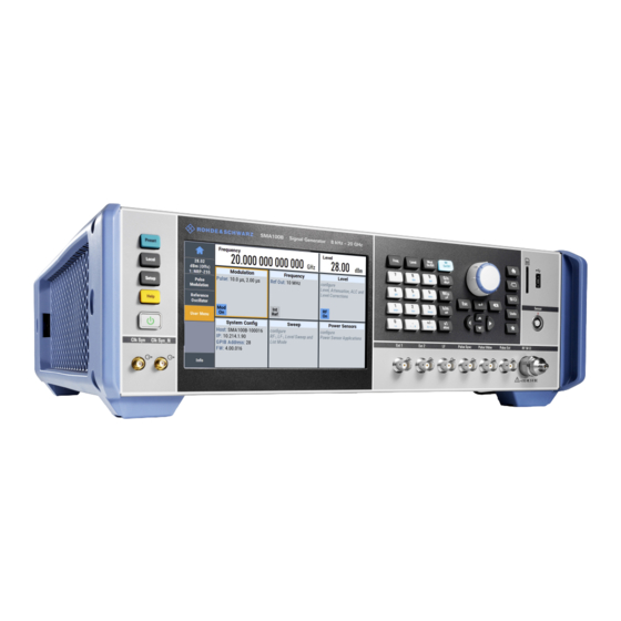
® Instrument Tour R&S SMA100B Front Panel Tour Figure 5-2: Front panel view of the R&S SMA100B RF Signal Generator with height unit 3HU (option R&S SMAB-B93) 1 = Touchscreen 2 = Utility keys 3 = [On/Standby] 4 = Function keys... - Page 23 ● Never scratch the screen surface, for example with a finger nail. ● Never rub the screen surface strongly, for example with a dust cloth. For instructions on cleaning the screen, see the Maintenance chapter in the R&S SMA100B user manual. Getting Started 1419.8620.02 ─ 07...
-
Page 24: Utility Keys
Instrument Tour R&S SMA100B Front Panel Tour 5.1.2 Utility Keys The utility keys set the R&S SMA100B to a defined state, and provide access to basic settings and information on assistance. Table 5-1: Utility keys Utility Key Assigned functions [Preset]... -
Page 25: Keypad
® Instrument Tour R&S SMA100B Front Panel Tour 5.1.5 Keypad The keypad enables you to enter alphanumeric parameters, including the corre- sponding units. It contains the following keys: Table 5-3: Keys on the keypad Type of key Description Alphanumeric keys Enter numbers and (special) characters in edit dialog boxes. -
Page 26: Navigation Keys
® Instrument Tour R&S SMA100B Front Panel Tour Table 5-4: Editing keys Type of key Description [Esc] key Closes all kinds of dialog boxes, if the edit mode is not active. Quits the edit mode, if the edit mode is active. In dialog boxes that contain a "Cancel"... -
Page 27: Display Keys
® Instrument Tour R&S SMA100B Front Panel Tour 5.1.7 Display Keys The display keys arrange different windows on the display. Table 5-6: Display keys Display key Assigned functions [Home] Returns to the initial feature screen. [Next window] Toggles between the entry fields in the taskbar. -
Page 28: Rf 50 Ω
The R&S SMA100B supports the use of R&S NRP power sensors in various ways including the use as a power viewer. A power sensor is connected to the R&S SMA100B by inserting the male connec- tor. To disconnect, pull the connector by its sleeve. You cannot disconnect the sensor simply by pulling at the cable or the rear part of the connector. -
Page 29: 5.1.12 Pulse Signal Connectors
The application notes are available on the Internet and provide additional information on care and handling of RF connectors. Rohde & Schwarz offers appropriate torque wrenches for various connec- tors. For ordering information, see the R&S SMA100B data sheet or product brochure. 5.1.12 Pulse Signal Connectors Pulse Sync Output signal for synchronizing the pulse generator signal. -
Page 30: 5.1.13 Lf Modulation Connectors
This section provides an overview of the connectors at the rear panel of the instrument. For technical data of the connectors, refer to the data sheet. Figure 5-4: Rear panel view of the R&S SMA100B RF Signal Generator with height unit 2HU (option R&S SMAB-B92) - Page 31 18 = RF output connector 19 = Serial number (six digits in the string 1419.8888.02-<serial number>-<checksum>) Figure 5-5: Rear panel view of the R&S SMA100B RF Signal Generator with height unit 3HU (option R&S SMAB-B93) 1 = IEC 625/IEEE 488 connector...
-
Page 32: Connectors
See also Chapter 4.2, "Connecting USB Devices", on page 20. The LAN interface can be used to connect the R&S SMA100B to a local network for remote control, remote operation, and data transfer. V/GHz X-Axis Output of a voltage ramp: ●... - Page 33 This connector is bidirectional. Used as: ● "Input": enables you to stop a sweep triggered by an external network ana- lyzer. ● "Output": enables the R&S SMA100B to stop the sweep of an external net- work analyzer. Marker User1 Output signal for marker or trigger signal.
- Page 34 ® Instrument Tour R&S SMA100B Rear Panel Tour Output for internal LF generator signal. See also data sheet and user manual, section "Analog Modulation". Ext 1/2 Inputs for external analog modulation signal, and an external detector voltage. AC supply and power switch The AC power supply connector and the main power switch are located in a unit on the rear panel of the instrument.
-
Page 35: Trying Out The Instrument
We start to generate a simple unmodulated signal. In this example, the R&S SMA100B can be in its minimal configuration. 1. On the R&S SMA100B front panel, press the [Preset] key to set a defined ini- tial instrument state. 2. Set the frequency: a) In the "Status Bar", tap the "Frequency"... - Page 36 ® Trying Out the Instrument R&S SMA100B Generating an Unmodulated Carrier The on-screen key pad closes and the frequency value is displayed. 3. To set the signal level, tap the "Level" field and enter the level in the same way.
- Page 37 SMA100B Generating an Unmodulated Carrier The blue colored "RF On" icon indicates that the RF output is activated. The R&S SMA100B provides the 6 GHz signal at the RF A connector at the front panel. Getting Started 1419.8620.02 ─ 07...
- Page 38 ® Trying Out the Instrument R&S SMA100B Generating an Unmodulated Carrier Figure 6-1: Generating an unmodulated signal Alternative ways to access the instrument functions To fulfill the same task, you can also use the front panel keys or the setting parameters provided in the frequency and level dialogs.
-
Page 39: Generating An Rf Frequency Sweep Signal
Trying Out the Instrument R&S SMA100B Generating an RF Frequency Sweep Signal Connect RF of the R&S SMA100B to a signal analyzer, for example ® R&S FSW, to display the generated signal. For the required settings of the signal analyzer, refer to its user manual or its online help. - Page 40 ® Trying Out the Instrument R&S SMA100B Generating an RF Frequency Sweep Signal a) Select "Mode > Auto" to run the sweep continuously. b) Select "Shape > Sawtooth" to set the waveform shape of the sweep signal. c) Select "Spacing > Linear", to determine the calculation method for the fre- quency shift of a step.
-
Page 41: Saving And Recalling Settings
7. Close the sweep dialog. (Alternatively, tap the "Home" button to minimize the dialog. The R&S SMA100B indicates the "Sweep" dialog as active dialog in the task bar.) 8. To activate the RF signal output, select "Level" > "RF On". - Page 42 ® Trying Out the Instrument R&S SMA100B Saving and Recalling Settings 2. In the "Setup" menu, select "Settings > Save/Recall". 3. In the "Save/Recall" dialog, select "Operation Mode > Save". 4. Tap the "Filename", use the on-screen keyboard, and enter MyTestSignal.
- Page 43 ® Trying Out the Instrument R&S SMA100B Saving and Recalling Settings Navigate to the directory the file is saved in and select the MyTestSignal file. 5. Tap the "Recall" button. All instrument settings are restored and the display resembles Chapter 6.2, "Generating an RF Frequency Sweep...
- Page 44 ® Trying Out the Instrument R&S SMA100B Saving and Recalling Settings ● All changed parameters are highlighted. Getting Started 1419.8620.02 ─ 07...
-
Page 45: Instrument Control
® Instrument Control R&S SMA100B Possible Ways to Operate the Instrument Instrument Control This chapter provides an overview on how to work with the R&S SMA100B. It covers the following topics: ● Possible Ways to Operate the Instrument............47 ● Means of Manual Interaction................48... -
Page 46: Means Of Manual Interaction
Understanding the Display Information The home screen of the R&S SMA100B displays all main settings and generator states, divided into three main operation areas. Getting Started 1419.8620.02 ─ 07... -
Page 47: Status Bar
The status bar at the top of the screen indicates the RF frequency and the level of the output signal provided to the DUT. You can set both parameters directly here. 7.3.2 Tile Diagram The tile diagram is the main entry to the settings of the R&S SMA100B. Tile Access to: ●... -
Page 48: Taskbar
® Instrument Control R&S SMA100B Understanding the Display Information Tile Access to: ● "Frequency" RF frequency and phase ● Reference frequency ● "Level" RF level ● Attenuator ● Automatic level control ● User correction ● "Clk Syn / Pow Clock synthesis Sens"... -
Page 49: Additional Display Characteristics
® Instrument Control R&S SMA100B Understanding the Display Information Active dialogs Indicates the dialog name of each active dialog in a separate button. "Info" key Provides access to status and error messages. Note: The warning symbol signifies a permanent error message. -
Page 50: Accessing The Functionality
® Instrument Control R&S SMA100B Accessing the Functionality Within the entire screen display, including single parameters, you can access context-sensitive menus that provide some additional functions. Accessing the Functionality All functionalities are provided in dialog boxes as known from computer pro- grams. -
Page 51: Entering Data
® Instrument Control R&S SMA100B Entering Data ● Tap the required tile, and then the menu entry. ● Tap the minimized view (button) on the taskbar. Some of the utility keys access a dedicated dialog, too. To minimize a dialog box 1. -
Page 52: Entering Numeric Parameters
® Instrument Control R&S SMA100B Entering Data Completing the entry ► Press the [Enter] key or the rotary knob. Aborting the entry ► Press the [Esc] key. The dialog box closes without changing the settings. 7.5.1 Entering Numeric Parameters To enter values with the on-screen keypad For numeric settings, the instrument displays the numeric keypad. -
Page 53: Undo And Redo Actions
® Instrument Control R&S SMA100B Getting Information and Help 7.5.3 Undo and Redo Actions Accessed via the context-sensitive menus, "Undo" allows you to restore one or more actions on the instrument. Depending on the available memory, the "Undo" steps can restore all actions. - Page 54 ® Instrument Control R&S SMA100B Getting Information and Help Contents of the help dialog box The help dialog box covers two main areas: ● "Contents" - contains a table of help contents ● "Topic" - contains a specific help topic The help system also provides an "Index"...
-
Page 55: Remote Control
The corresponding help topic is displayed. Remote Control In addition to working with the R&S SMA100B interactively, located directly at the instrument, it is also possible to operate and control it from a remote PC. The R&S SMA100B supports various methods for remote control: ●... -
Page 56: Remote Operation Over Vnc
Thus, remote operation of the instrument is possible. Instrument control from a remote computer To access the basic utility functions of the R&S SMA100B, perform a right mouse click on the block diagram and select "Key Emulation". -
Page 57: Index
® Index R&S SMA100B Index Display Active elements ........51 AC supply ..........17 Context-sensitive menu ...... 51 Active elements ........51 Info line ..........51 Alphanumeric parameters ....... 54 Information .......... 48 Application cards ........11 On-screen keypad ......51 Application notes ........ - Page 58 ® Index R&S SMA100B Navigation ★ (User) ..........29 Keys ............ 28 Navigation controls Access on a remote computer .... 58 Arrow ..........28 Overview ..........27 Network connection Backspace .......... 27 Error ............ 22 Down ...........28 Emulation ..........58 Numeric data entry ........
- Page 59 ® Index R&S SMA100B Rotary knob ..........27 User manual ..........9 Utility keys Safety instructions ........10 Details - see user manual ....26 Saving ............. 43 Overview ..........26 SD card slot ..........29 Service manual ..........9 Shutting down ..........18 V/GHz X-Axis connector ......34...
Need help?
Do you have a question about the SMA100B and is the answer not in the manual?
Questions and answers