Table of Contents
Advertisement
Quick Links
Advertisement
Table of Contents

Related Manuals for R&S SMBV100B


Summary of Contents for R&S SMBV100B
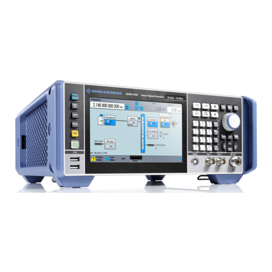
- Page 1 ® R&S SMBV100B Vector Signal Generator Getting Started (>G:a2) 1423104902...
- Page 2 ® This document describes the R&S SMBV100B, stock no. 1423.1003.02 and its options. © 2019 Rohde & Schwarz GmbH & Co. KG Mühldorfstr. 15, 81671 München, Germany Phone: +49 89 41 29 - 0 Fax: +49 89 41 29 12 164 Email: info@rohde-schwarz.com...
-
Page 3: Table Of Contents
4.2 Unpacking and Checking..............17 4.3 Choosing the Operating Site............. 18 4.4 Setting Up the R&S SMBV100B............18 4.4.1 Placing the R&S SMBV100B on a Bench Top........18 4.4.2 Mounting the R&S SMBV100B in a Rack..........19 4.5 Important Aspects for Test Setup............20 4.6 Connecting to Power................ - Page 4 ® Contents R&S SMBV100B 4.7 Connecting to LAN................22 4.8 Connecting USB Devices..............23 4.9 Connecting to RF................24 4.10 Connecting to LO In/Out..............24 4.11 Connecting to Ref In/Ref Out.............25 4.12 Connecting to HS Dig I/Q..............26 4.13 Switching On or Off................27 5 Instrument Tour..............
- Page 5 7.7 I/Q Modulator ("I/Q Mod" Block)............70 7.8 Analog I/Q Output ("I/Q Analog" Block)..........71 7.9 RF and Analog Modulations ("RF" Block)........71 7.10 Applications Examples of the R&S SMBV100B....... 71 8 Instrument Control.............. 73 8.1 Possible Ways to Operate the Instrument........73 8.2 Means of Manual Interaction..............74...
- Page 6 ® Contents R&S SMBV100B 8.5.3 Undo and Redo Actions................ 83 8.6 Getting Information and Help............83 8.7 Remote Control................... 85 8.8 Remote Operation over VNC..............86 9 Contacting Customer Support........... 87 Index..................89 Getting Started 1423.1049.02 ─ 05...
-
Page 7: Preface
R&S SMBV100B Key Features Preface The R&S SMBV100B is a new signal generator developed to meet demanding customer requirements. Offering excellent signal characteristic and straightfor- ward and intuitive operation, the signal generator makes signal generation fast and easy. Key Features The R&S SMBV100B is a new high-performance signal generator developed to... - Page 8 ® Preface R&S SMBV100B Key Features Getting Started 1423.1049.02 ─ 05...
-
Page 9: Safety And Regulatory Information
Safety and Regulatory Information R&S SMBV100B Safety Instructions Safety and Regulatory Information The product documentation helps you use the R&S SMBV100B safely and effi- ciently. Follow the instructions provided here and in the Chapter 2.1, "Safety Instructions", on page 9. - Page 10 ® Safety and Regulatory Information R&S SMBV100B Safety Instructions If any part of the product is damaged or broken, stop using the product. Never open the casing of the product. Only service personnel authorized by Rohde & Schwarz are allowed to repair the product. Contact Rohde & Schwarz customer service at http://www.customersupport.rohde-schwarz.com.
- Page 11 ® Safety and Regulatory Information R&S SMBV100B Safety Instructions Take the following measures for your safety: ● Before switching on the product, ensure that the voltage and frequency indica- ted on the product match the available power source. If the power adapter does not adjust automatically, set the correct value and check the rating of the fuse.
-
Page 12: Labels On R&S Smbv100B
Table 2-1: Labels regarding R&S SMBV100B and environment safety Labeling in line with EN 50419 for disposal of electrical and electronic equipment after the product has come to the end of its service life. For more information, see the prod- uct user manual, chapter "Disposal". -
Page 13: Documentation Overview
Getting Started Manual Introduces the R&S SMBV100B and describes how to set up and start working with the product. Includes basic operations, typical measurement examples, and general information, e.g. safety instructions, etc. A printed version is delivered with the instrument. -
Page 14: Service Manual
Rohde & Schwarz information system (GLORIS, https://gloris.rohde- schwarz.com). Instrument Security Procedures Deals with security issues when working with the R&S SMBV100B in secure areas. It is available for download on the Internet. Basic Safety Instructions Contains safety instructions, operating conditions and further important informa- tion. -
Page 15: Release Notes And Open Source Acknowledgment (Osa)
® Documentation Overview R&S SMBV100B Application Notes, Application Cards, White Papers, etc. Release Notes and Open Source Acknowledg- ment (OSA) The release notes list new features, improvements and known issues of the cur- rent firmware version, and describe the firmware installation. - Page 16 ® Documentation Overview R&S SMBV100B Application Notes, Application Cards, White Papers, etc. Getting Started 1423.1049.02 ─ 05...
-
Page 17: Preparing For Use
"Lifting and carrying the product" on page 10. ► Use the carrying handle at the side for lifting and carrying the R&S SMBV100B. For mounting the R&S SMBV100B in a rack, see Chapter 4.4.2, "Mounting the R&S SMBV100B in a Rack", on page 19. -
Page 18: Choosing The Operating Site
Electromagnetic compatibility classes The electromagnetic compatibility (EMC) class indicates where you can operate the R&S SMBV100B. The EMC class of the R&S SMBV100B is given in the data sheet under "General data". ● Class B equipment is suitable for use in: –... -
Page 19: Mounting The R&S Smbv100B In A Rack
● Keep a minimum distance of 10 cm between the fan openings of the R&S SMBV100B and any object in the vicinity. ● Do not place the R&S SMBV100B next to heat-generating equipment such as radiators or other instruments. 4.4.2 Mounting the R&S SMBV100B in a Rack... -
Page 20: Important Aspects For Test Setup
Design and implement an efficient ventilation concept for the rack. To mount the R&S SMBV100B in a rack 1. Use an adapter kit that fits the dimensions of the R&S SMBV100B to prepare the instrument for rack mounting. For information on the dimensions, see data sheet. - Page 21 26 Signal input and output levels Information on signal levels is provided in the data sheet. Keep the signal levels within the specified ranges to avoid damage to the R&S SMBV100B and connec- ted devices. Preventing electrostatic discharge (ESD) Electrostatic discharge is most likely to occur when you connect or disconnect a DUT.
-
Page 22: Connecting To Power
Connecting to LAN You can operate the R&S SMBV100B via LAN (local area network) or you can operate it locally. This section describes how to connect the instrument to a LAN to operate or control the instrument remotely via a PC in a LAN. -
Page 23: Connecting Usb Devices
You can connect or disconnect all USB devices from the R&S SMBV100B during operation. To connect USB storage devices USB storage devices, such as memory sticks, allow easy data transfer from/to the R&S SMBV100B. You can also use them for firmware updates. -
Page 24: Connecting To Rf
RF output connector is located on the rear panel. To prepare for connecting to "RF" 1. If the R&S SMBV100B is switched on, deactivate the RF output, before con- necting an RF cable to the RF connector. In the block diagram, select the block "RF" > "RF Level" > "RF ON > Off". -
Page 25: Connecting To Ref In/Ref Out
® Preparing for Use R&S SMBV100B Connecting to Ref In/Ref Out 1. Use a high-quality cable that matches the connector type. "Cable selection and electromagnetic interference (EMI)" on page 20. 2. NOTICE! Risk of instrument damage and connector damage. Excessive tight- ening can damage the cables and the connectors. -
Page 26: Connecting To Hs Dig I/Q
R&S SMBV100B Connecting to HS Dig I/Q To connect to "Ref In"/"Ref Out" (reference < 1 GHz) For connection, the R&S SMBV100B provides BNC connectors. ► Follow the instructions in "To connect to non-screwable connectors (BNC)" on page 24. To connect to "Ref In"/"Ref Out" (reference = 1 GHz) For connection, the R&S SMBV100B provides SMA connectors. -
Page 27: Switching On Or Off
® Preparing for Use R&S SMBV100B Switching On or Off 1 = QSFP+ plug 2 = QSFP+ cage 3 = QSFP+ connector The connector is located on the rear panel. To connect to HS Dig I/Q interface 1. For connection, use the QSFP+ cable R&S DIGIQ-HS. - Page 28 The LED changes to green. The R&S SMBV100B boots. When starting for the first time, the R&S SMBV100B starts with the default settings. When restarting the instrument, the settings depend on the instru- ment configuration before shut-down. See the chapter "Saving and Recalling Instrument Settings" in the user man- ual.
- Page 29 To disconnect from power The R&S SMBV100B is in the standby state. 1. NOTICE! Risk of data loss. If you disconnect the R&S SMBV100B from power when it is in the ready state, you can lose settings and data. Shut it down first.
- Page 30 ® Preparing for Use R&S SMBV100B Switching On or Off Getting Started 1423.1049.02 ─ 05...
-
Page 31: Instrument Tour
Rear Panel Tour This section explains the control elements and the connectors of the R&S SMBV100B with the aid of the front and rear views. For specifications of the interfaces, refer to the data sheet. The meanings of the labels on the R&S SMBV100B are described in Chapter 2.2,... -
Page 32: Touchscreen
® Instrument Tour R&S SMBV100B Front Panel Tour 4 = Function keys, see Chapter 5.1.2.3, "Function Keys", on page 34 5 = Keypad, see Chapter 5.1.2.4, "Keypad", on page 34 6 = Navigation controls, see Chapter 5.1.2.6, "Navigation Controls", on page 35 7 = USB connectors, see Chapter 5.1.3,... -
Page 33: Keys
5.1.2 Keys 5.1.2.1 Utility Keys The utility keys cause the R&S SMBV100B to return to a defined instrument state and provide information on the instrument and assistance. For more information, refer to chapter "General Instrument Functions" in the user manual. -
Page 34: Function Keys
® Instrument Tour R&S SMBV100B Front Panel Tour The LED above the [On/Standby] key indicates the instrument state, see Chap- ter 4.13, "Switching On or Off", on page 27. 5.1.2.3 Function Keys Function keys provide access to most common generator settings and functions. -
Page 35: Editing Keys
® Instrument Tour R&S SMBV100B Front Panel Tour Type of key Description Sign key Changes the sign of a numeric parameter. In the case of an alphanumeric parameter, inserts a "-" at the cursor position. Unit keys These keys add the selected unit to the entered numeric value and complete the entry. -
Page 36: Navigation Keys
® Instrument Tour R&S SMBV100B Front Panel Tour ● Increments (clockwise direction) or decrements (counterclockwise direction) the instrument parameter at a defined step width in the case of a numeric entry. ● Moves the selection, e.g. to a function block in the block diagram ●... -
Page 37: Connectors
Sensor Connector for R&S NRP sensors. A power sensor is connected to the R&S SMBV100B by inserting the male con- nector. To disconnect, pull the connector by its sleeve. You cannot disconnect the sensor simply by pulling at the cable or the rear part of the connector. -
Page 38: Rear Panel Tour
® Instrument Tour R&S SMBV100B Rear Panel Tour ● yellow: an output connector ● no light / gray: the connector is not active See also chapter "Global Connector Settings" in the user manual. Output for RF signal. The connector type depends on the installed frequency option. -
Page 39: Connectors
® Instrument Tour R&S SMBV100B Rear Panel Tour = Ref In/Ref Out connectors = Ref In/Ref Out 1GHz connectors = LF connector = Mod Ext connector = Pulse Video connector = Pulse Ext connector = Signal Valid connector = Inst Trig connectors... - Page 40 ® Instrument Tour R&S SMBV100B Rear Panel Tour Dig I/Q Connectors for the input of a digital I/Q signal from a Rohde & Schwarz instru- ment, like a signal generator. HS Dig I/Q Connectors for the input of high-speed digital I/Q signals, for example, from Rohde &...
- Page 41 The interface is in compliance with the standards IEC 625, IEEE 488 and SCPI. Use this interface to connect a computer for remote control of the R&S SMBV100B. To set up the connection, use high-quality shielded cables. See "Cable selection and electromagnetic interference (EMI)" on page 20.
- Page 42 ● Female USB In connector (USB type B), for example for remote control. How to: Chapter 4.8, "Connecting USB Devices", on page 23 RJ-45 connector to connect the R&S SMBV100B to a LAN for remote control, remote operation, and data transfer. How to: Chapter 4.7, "Connecting to LAN",...
-
Page 43: Trying Out The Instrument
This chapter introduces the most important functions and settings of the R&S SMBV100B step by step. The complete description of the functionality and its usage is given in the R&S SMBV100B user manual. Basic instrument opera- tion is described in Chapter 8, "Instrument... - Page 44 Trying Out the Instrument R&S SMBV100B Generating an Unmodulated Carrier 1. On the R&S SMBV100B front panel, press the Preset key to start out in a defined instrument configuration. 2. Set the frequency: a) On the "Status Bar", tap the "Frequency" field.
- Page 45 Figure 6-1: Block diagram: Generating an unmodulated signal The 1.95 GHz signal is output at the RF connector at the front panel of the R&S SMBV100B. Connect RF of the R&S SMBV100B to a signal analyzer, for example ® R&S FSW, to display the generated signal.
-
Page 46: Generating A Digitally Modulated Signal
This example shows you how to generate a simple WCDMA-3GPP (QPSK 45° offset) signal with the help of the "Custom Digital Modulation" functionality. The minimum requirement for R&S SMBV100B in this example is a base unit equipped with: ● Option custom digital modulation R&S SMBVB-K520 ●... - Page 47 ® Trying Out the Instrument R&S SMBV100B Generating a Digitally Modulated Signal 4. Select the "Modulation" tab and observe the used "Modulation Type". Figure 6-3: Display of the used modulation type The instrument activates automatically "I/Q Mod", uses the internal trigger and clock signals, and generates a WCDMA-3GPP signal, modulated with a QPSK 45°...
-
Page 48: Triggering The Instrument With An External Signal
Triggering the Instrument with an External Sig- The example configurations are rather theoretical cases, because you rarely use the R&S SMBV100B as a standalone instrument. Usually, the instrument would be connected to a device under test (DUT) and/or other measurement equipment. - Page 49 53 To verify the current connector configuration The R&S SMBV100B is equipped with multipurpose bi-directional User connec- tors. Because the signal direction, input or output, and the signal mapping are configurable, we recommend that you check the current configuration before cabling or further instrument's configurations.
- Page 50 ® Trying Out the Instrument R&S SMBV100B Triggering the Instrument with an External Signal The instrument uses its internal trigger and clock signals, and the default map- ping of the marker signals to the connectors. 2. To access the related connector settings, perform one of the following: ●...
- Page 51 ® Trying Out the Instrument R&S SMBV100B Triggering the Instrument with an External Signal Figure 6-5: Signal mapping to the global connectors The "Global Connectors" dialog displays the current connectors configuration. The settings are configurable, but in this example we use the default mapping.
- Page 52 ® Trying Out the Instrument R&S SMBV100B Triggering the Instrument with an External Signal a) "Mode > Armed Auto" b) "Source > External Global Trigger". 3. Select "Global Connector Settings > Routing". 4. For "User 2", select "Direction > Input" and "Signal > Global Trigger".
- Page 53 Instead of using an external trigger source, the DUT can also send, for example, a frame trigger signal to the R&S SMBV100B. The R&S SMBV100B acts still as the signal source. Getting Started 1423.1049.02 ─ 05...
-
Page 54: Enabling And Configuring A Marker Signal
User 1 connector of the R&S SMBV100B (see Figure 6-5). 3. Use a suitable cable to connect the User 1 connector of the R&S SMBV100B ® to the monitoring instrument, for example oscilloscope like R&S RTO. See Figure 6-7. -
Page 55: Verifying The Generated Signal With The Graphics Display
It is often useful to check the spectra of the configured signals, before you enable the RF output of the instrument. The R&S SMBV100B provides a build-in function to represent the generated sig- nal on a graphical signal display. We demonstrate this feature by showing the characteristics at one particular point of the signal processing chain. - Page 56 ® Trying Out the Instrument R&S SMBV100B Verifying the Generated Signal with the Graphics Display a) Select "Taskbar > System Configuration > Graphics" b) On the "Taskbar", tap the wave icon. The "Graphics Configuration" dialog opens. To visualize the signal 1.
- Page 57 ® Trying Out the Instrument R&S SMBV100B Verifying the Generated Signal with the Graphics Display A new thumbnail (minimized view) indicating the active diagram appears in the "Taskbar". 4. Press the thumbnail graphic. The graphic enlarges and the diagram is displayed in a normal size.
-
Page 58: Saving And Recalling Settings
® Trying Out the Instrument R&S SMBV100B Saving and Recalling Settings Saving and Recalling Settings To restore the results of our measurements later, we save the instrument settings to a file. To save the instrument settings to a file We assume, a test configuration as described in Chapter 6.4, "Enabling and Con-... - Page 59 ® Trying Out the Instrument R&S SMBV100B Saving and Recalling Settings 3. Tap the "Save" button. The file MyTestSignal.savrcltxt is saved in the default directory /var/ user. To load saved instrument settings You can restore the settings to the instrument at any time using the settings file.
- Page 60 ® Trying Out the Instrument R&S SMBV100B Saving and Recalling Settings 4. Tap the "Recall" button. All instrument settings are restored and the display resembles the instrument display right before the settings were saved. How to display all parameters with values different to their preset val-...
-
Page 61: Generating An Eutra/Lte Signal
● All changed parameters are highlighted. Generating an EUTRA/LTE Signal The main application field of the R&S SMBV100B is the generation of digital sig- nals in accordance with several telecommunication and wireless standards, like WCDMA, EUTRA/LTE or WLAN, to name a few. This example uses the digital standard EUTRA/LTE to introduce the way you can access and interact with the instrument and experience the advantages provided by the additional options. - Page 62 We use one of the provided EUTRA test models (E-TM) to show how to generate a test signal upon a quick selection. 1. On the R&S SMBV100B front panel, press the Preset key to start out in a defined instrument configuration.
- Page 63 ® Trying Out the Instrument R&S SMBV100B Generating an EUTRA/LTE Signal As in the user interfaces of all digital standards, the "EUTRA/LTE" dialog is divided into several tabs. The "General" tab comprises the primary settings of the standard, the functions for storing and recalling settings and provides access to further functions and dialogs, like the "Filter"...
- Page 64 ® Trying Out the Instrument R&S SMBV100B Generating an EUTRA/LTE Signal The dialog closes automatically and the user interface confirms the name of the selected file. 5. In the "EUTRA/LTE > General" tab, select "State > On". Close the dialog.
- Page 65 With these first steps, you have gained an impression of the provided func- tionality. For a comprehensive description of the full range of capabilities, refer to the user manual "EUTRA/LTE Digital Standard for R&S SMBV100B". Getting Started 1423.1049.02 ─ 05...
- Page 66 ® Trying Out the Instrument R&S SMBV100B Generating an EUTRA/LTE Signal Getting Started 1423.1049.02 ─ 05...
-
Page 67: System Overview
Signal Flow at a Glance System Overview This section helps you to get familiar with the R&S SMBV100B. It provides an introduction to the general concept of the instrument. This section also introduces the main blocks in the signal generation flow. - Page 68 The information assumes R&S SMBV100B base unit. For exact information on the available options, and on the minimum requirements and the interdependencies between the provided options, refer to the R&S SMBV100B data sheet.
-
Page 69: Internal Baseband Source ("Baseband" Block)
The "BB Input" block is the access point to the settings of the digital interfaces. The R&S SMBV100B is able to receive and process digital baseband signals. The digital baseband input can be used together with other Rohde & Schwarz instruments, like signal generators. -
Page 70: Additional White Gaussian Noise ("Awgn" Block)
® System Overview R&S SMBV100B I/Q Modulator ("I/Q Mod" Block) nal digital signals cannot be used simultaneously. The two blocks "Baseband" and "BB Input" deactivate each other. The "BB Input" block is the access point to the settings of: ● The external digital I/Q signals The external digital I/Q signals are further processed in the baseband section ●... -
Page 71: Analog I/Q Output ("I/Q Analog" Block)
● Generation of digitally modulated signal The main field of application of the R&S SMBV100B is the generation of digi- tally modulated signals. The R&S SMBV100B generates a digitally modulated signal in several ways: using the internal baseband generator, using the exter- nally applied digital baseband signals or in an analog wideband I/Q operation. - Page 72 ® System Overview R&S SMBV100B Applications Examples of the R&S SMBV100B Getting Started 1423.1049.02 ─ 05...
-
Page 73: Instrument Control
® Instrument Control R&S SMBV100B Possible Ways to Operate the Instrument Instrument Control This chapter provides an overview on how to work with the R&S SMBV100B. It covers the following topics: ● Possible Ways to Operate the Instrument............73 ● Means of Manual Interaction................74... -
Page 74: Means Of Manual Interaction
SMBV100B Means of Manual Interaction Means of Manual Interaction For the manual interaction with the R&S SMBV100B, you have several methods that you can use as an alternative to perform a task: ● Touchscreen: Touchscreen operation is the most direct way to interact. Almost all control elements and actions on the screen are based on the standard operating sys- tem concept. -
Page 75: Understanding The Display Information
SMBV100B Understanding the Display Information Understanding the Display Information The block diagram of the R&S SMBV100B displays all main settings and genera- tor states, divided into three main operation areas. Figure 8-1: Block diagram 1 = Status bar (frequency and level display) -
Page 76: Block Diagram
® Instrument Control R&S SMBV100B Understanding the Display Information 1 = Frequency display 2 = Status buttons 3 = Level display The status buttons indicate key parameters that are set for the output signal. Most of the status buttons are virtual keys you can use to open a corresponding menu or dialog. -
Page 77: Taskbar
® Instrument Control R&S SMBV100B Understanding the Display Information Legend Item Description Status indicator Indicates whether the signal is running or waiting for a trigger. Functional block Represents a basic task in signal generation. The push button provides access to any number of asso- ciated actions to accomplish the task. -
Page 78: Additional Display Characteristics
® Instrument Control R&S SMBV100B Understanding the Display Information Whenever you open a settings or graphics dialog, it is automatically assigned to the "Taskbar". The softkeys shown in the following figure represent the variants. Figure 8-3: Taskbar fully assigned 1 = System configuration... - Page 79 ® Instrument Control R&S SMBV100B Understanding the Display Information ● On-Screen keypads As additional means of interacting with the instrument without having to con- nect an external keyboard, either a numerical or alphanumerical on-screen keypad appears when you activate an entry field (see Chapter 8.5, "Entering...
-
Page 80: Accessing The Functionality
® Instrument Control R&S SMBV100B Accessing the Functionality Accessing the Functionality All functionalities are provided in dialog boxes as known from computer pro- grams. You can control the instrument intuitively with the touchscreen. This sec- tion provides an overview of the accessing methods. - Page 81 ® Instrument Control R&S SMBV100B Accessing the Functionality ● Tap the required block, and then the menu entry. ● Tap the minimized view (thumbnail) on the taskbar. Some of the utility keys access a dedicated dialog, too. To minimize a dialog box ►...
-
Page 82: Entering Data
® Instrument Control R&S SMBV100B Entering Data Entering Data Some parameters have their own key on the front panel. For data input in dialog boxes, the instrument provides on-screen keypads for entering numeric and alphanumeric values. Thus, you can always set the param- eters via the touchscreen, the front panel, or an external keyboard. -
Page 83: Entering Alphanumeric Parameters
® Instrument Control R&S SMBV100B Getting Information and Help To enter values by using the front panel controls 1. Change the currently used parameter value by using the rotary knob or the [Up/Down] keys. 2. If the parameter does not require a unit, confirm the entered value by pressing the [Enter] key or any of the unit keys. - Page 84 ® Instrument Control R&S SMBV100B Getting Information and Help To display context help ► To access a help topic, perform one of the following: a) Tap and hold the parameter for which you need information and tap "Help" in the context menu.
-
Page 85: Remote Control
The corresponding help topic is displayed. Remote Control In addition to working with the R&S SMBV100B interactively, located directly at the instrument, it is also possible to operate and control it from a remote PC. The R&S SMBV100B supports various methods for remote control: ●... -
Page 86: Remote Operation Over Vnc
Thus, remote operation of the instrument is possible. Instrument control from a remote computer To access the basic utility functions of the R&S SMBV100B, perform a right mouse click on the block diagram and select "Key Emulation". -
Page 87: Contacting Customer Support
® Contacting Customer Support R&S SMBV100B Contacting Customer Support Technical support – where and when you need it For quick, expert help with any Rohde & Schwarz equipment, contact one of our Customer Support Centers. A team of highly qualified engineers provides tele- phone support and works with you to find a solution to your query on any aspect of the operation, programming or applications of Rohde &... - Page 88 ® Contacting Customer Support R&S SMBV100B Getting Started 1423.1049.02 ─ 05...
-
Page 89: Index
® Index R&S SMBV100B Index LAN ............. 42 LF ............40 Active elements ........78 LO In ........... 40 Alphanumeric parameters ....... 83 LO Out ..........40 Application cards ........15 Mod Ext ..........41 Application notes ........15 Pulse Ext ..........41 ARB ............ - Page 90 ® Index R&S SMBV100B Function keys Right ........... 36 Details - see user manual ....34 Save/Rcl ..........33 Overview ..........34 Setup ..........33 Up ............36 Keyboard On-screen ........... 82 Getting started ......... 13 Usage ..........74 Keypad On-screen ...........
- Page 91 ® Index R&S SMBV100B Power Utility keys Connecting the instrument ....22 Details - see user manual ....33 Power on Overview ..........33 Key ............33 Power supply Connector ........... 42 Preparing for use ........17 Using in a LAN ........86 Rack, mounting ........
Need help?
Do you have a question about the SMBV100B and is the answer not in the manual?
Questions and answers