
Related Manuals for R&S SMCV100BP1


Summary of Contents for R&S SMCV100BP1
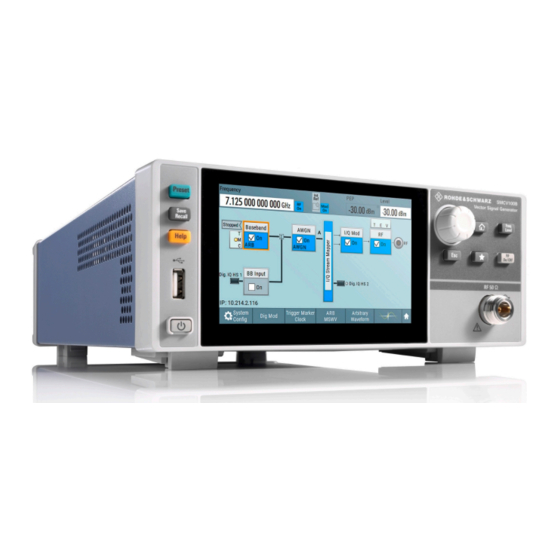
- Page 1 ® R&S SMCV100B Vector Signal Generator Getting Started (>PÔ^2) 1432704602 Version 04...
- Page 2 ® This document describes the R&S SMCV100B, stock no. 1432.7000.02 and its options. © 2022 Rohde & Schwarz GmbH & Co. KG Muehldorfstr. 15, 81671 Muenchen, Germany Phone: +49 89 41 29 - 0 Email: info@rohde-schwarz.com Internet: www.rohde-schwarz.com Subject to change – data without tolerance limits is not binding. R&S ®...
-
Page 3: Table Of Contents
® Contents R&S SMCV100B Contents 1 Safety and regulatory information........7 1.1 Safety instructions................7 1.2 Labels on R&S SMCV100B..............10 1.3 Warning messages in the documentation........10 1.4 Korea certification class B..............11 2 Documentation overview............ 12 2.1 Getting started manual...............12 2.2 User manuals and help...............12 2.3 Service manual..................13 2.4 Instrument security procedures............ - Page 4 ® Contents R&S SMCV100B 4.9 Connecting USB devices..............22 4.10 Connecting to RF 50 Ω............... 23 4.11 Connecting to Ref In/Ref Out.............24 4.12 Connecting to Dig. IQ HS x..............24 4.13 Connecting to IP Data interface............26 4.14 Switching on or off................27 5 Instrument tour..............
- Page 5 ® Contents R&S SMCV100B 7.9 Applications examples of the R&S SMCV100B........63 8 Instrument control............... 64 8.1 Possible ways to operate the instrument......... 64 8.2 Means of manual interaction............. 65 8.3 Understanding the display information..........65 8.4 Accessing the functionality............... 71 8.5 Entering data..................
- Page 6 ® Contents R&S SMCV100B Getting Started 1432.7046.02 ─ 04...
-
Page 7: Safety And Regulatory Information
® Safety and regulatory information R&S SMCV100B Safety instructions Safety and regulatory information The product documentation helps you use the product safely and efficiently. Fol- low the instructions provided here and in the following chapters. Intended use The product is intended for the development, production and verification of elec- tronic components and devices in industrial, administrative, and laboratory envi- ronments. - Page 8 ® Safety and regulatory information R&S SMCV100B Safety instructions Never open the casing of the product. Only service personnel authorized by Rohde & Schwarz are allowed to repair the product. If any part of the product is damaged or broken, stop using the product. Contact Rohde & Schwarz customer service at http://www.customersupport.rohde-schwarz.com.
- Page 9 ® Safety and regulatory information R&S SMCV100B Safety instructions Connecting to power The product is an overvoltage category II product. Connect the product to a fixed installation used to supply energy-consuming equipment such as household appliances and similar loads. Keep in mind that electrically powered products have risks, such as electric shock, fire, personal injury or even death.
-
Page 10: Labels On R&S Smcv100B
® Safety and regulatory information R&S SMCV100B Warning messages in the documentation Potential hazard Read the product documentation to avoid personal injury or product damage. Electrical hazard Indicates live parts. Risk of electric shock, fire, personal injury or even death. Hot surface Do not touch. -
Page 11: Korea Certification Class B
® Safety and regulatory information R&S SMCV100B Korea certification class B CAUTION Potentially hazardous situation. Could result in minor or moderate injury if not avoided. NOTICE Potential risks of damage. Could result in damage to the supported product or to other property. -
Page 12: Documentation Overview
® Documentation overview R&S SMCV100B User manuals and help Documentation overview This section provides an overview of the R&S SMCV100B user documentation. Unless specified otherwise, you find the documents on the R&S SMCV100B product page at: www.rohde-schwarz.com/manual/smcv100b Getting started manual Introduces the R&S SMCV100B and describes how to set up and start working with the product. -
Page 13: Service Manual
® Documentation overview R&S SMCV100B Data sheets and brochures Service manual Describes the performance test for checking compliance with rated specifications, firmware update, troubleshooting, adjustments, installing options and mainte- nance. The service manual is available for registered users on the global Rohde &... -
Page 14: Release Notes And Open Source Acknowledgment (Osa)
® Documentation overview R&S SMCV100B Application notes, application cards, white papers, etc. Release notes and open source acknowledg- ment (OSA) The release notes list new features, improvements and known issues of the cur- rent firmware version, and describe the firmware installation. The open-source acknowledgment document provides verbatim license texts of the used open source software. -
Page 15: Key Features
® Key features R&S SMCV100B Key features The R&S SMCV100B is a new signal generator in the economy range developed to meet demanding customer requirements. Offering excellent signal characteris- tic and straightforward and intuitive operation, the signal generator makes signal generation fast and easy. -
Page 16: Preparing For Use
® Preparing for use R&S SMCV100B Choosing the operating site Preparing for use Here, you can find basic information about setting up the product for the first time. Lifting and carrying See also "Lifting and carrying the product" on page 8. For mounting the R&S SMCV100B in a rack, see Chapter 4.4.2, "Mounting the R&S SMCV100B in a... -
Page 17: Setting Up The R&S Smcv100B
® Preparing for use R&S SMCV100B Setting up the R&S SMCV100B Electromagnetic compatibility classes The electromagnetic compatibility (EMC) class indicates where you can operate the product. The EMC class of the product is given in the data sheet under "Gen- eral data". - Page 18 ® Preparing for use R&S SMCV100B Setting up the R&S SMCV100B ● If the products have foldable feet, fold them in completely. ● All products must have the same dimensions (width and length). ● Do not exceed a total load of 50 kg placed on the product at the bottom of the stack.
-
Page 19: Considerations For Test Setup
® Preparing for use R&S SMCV100B Considerations for test setup b) Mount the adapter kit. Follow the assembly instructions provided with the adapter kit. 2. Lift the R&S SMCV100B to shelf height. 3. Push the R&S SMCV100B onto the shelf until the rack brackets fit closely to the rack. -
Page 20: Connecting To Power
® Preparing for use R&S SMCV100B Connecting to LAN ● Always terminate open cable ends. ● Ensure that connected external devices comply with EMC regulations. ● Use the cable R&S DIGIQ-HS for connection to the Dig. IQ HS x interfaces of the instrument. -
Page 21: Connecting A Monitor
® Preparing for use R&S SMCV100B Connecting a monitor ● Ensure that the network settings comply with the security policies of your com- pany. Contact your local system administrator or IT department before con- necting your product to your company LAN. ●... -
Page 22: Connecting Usb Devices
® Preparing for use R&S SMCV100B Connecting USB devices ● HDMI: You need an adapter. Use a passive DVI to HDMI adapter. ● VGA: You need an active adapter, DVI to VGA or Display Port to VGA. Passive adapters do not work. If the monitor provides touch functionality, an additional connection can be required, for example, a USB connection. -
Page 23: Connecting To Rf 50 Ω
® Preparing for use R&S SMCV100B Connecting to RF 50 Ω To connect a mouse ► Connect the mouse to any of the USB connectors. When connected, the R&S SMCV100B detects the mouse automatically. To connect power sensors You can connect power sensors of the R&S NRP families to any of the USB con- nectors. -
Page 24: Connecting To Ref In/Ref Out
® Preparing for use R&S SMCV100B Connecting to Dig. IQ HS x b) Mate the connectors along the common axis until the male pin of the con- nector of the cable engages with the female socket of the RF 50 Ω con- nector. - Page 25 ® Preparing for use R&S SMCV100B Connecting to Dig. IQ HS x 1 = QSFP+ plug 2 = QSFP+ cage 3 = QSFP+ connector The connector is located on the rear panel. To connect to Dig. IQ HS x interface 1.
-
Page 26: Connecting To Ip Data Interface
® Preparing for use R&S SMCV100B Connecting to IP Data interface 4.13 Connecting to IP Data interface The IP Data connector comprises an SFP+ (Small Form-factor Pluggable) socket, that has two components an SFP+ cage and an SFP+ connector. 1 = SFP+ cage 2 = SFP+ connector The connector is located on the rear... -
Page 27: Switching On Or Off
® Preparing for use R&S SMCV100B Switching on or off c) Insert and push the adapter into the cage of the SFP+ socket of the IP Data connector. d) To mount the adapter, push the release bracket down to close the bracket. The adapter is connected to the IP Data connector. - Page 28 ® Preparing for use R&S SMCV100B Switching on or off 2. Wait until the oven-controlled oscillator (OCXO) warms up. For the warm-up time, see data sheet. 3. Press the [On/Standby] key. Key and LED are located on the front panel. The LED changes to green.
-
Page 29: Instrument Tour
® Instrument tour R&S SMCV100B Front panel tour Instrument tour This chapter explains the control elements and the connectors of the R&S SMCV100B. The views of the front panel and the rear panel help you to get familiar with the instrument and to perform first steps. For specifications of the interfaces, see the data sheet. - Page 30 ® Instrument tour R&S SMCV100B Front panel tour 5.1.1 Touchscreen The block diagram and the most important settings are displayed on the screen on the front panel. Also, the screen display provides status and setting informa- tion and allows you to quickly reconfigure the signal flow. The screen is touch- sensitive, offering an alternative means of user interaction for quick and easy handling of the instrument.
- Page 31 ® Instrument tour R&S SMCV100B Front panel tour ● "Maintenance" in the user manual, for instructions on cleaning the screen. 5.1.2 Keys 5.1.2.1 On/Standby The [On/Standby] key switches the instrument from the standby to the ready state or vice versa. The LED below the [On/Standby] key indicates the instrument state, see Chap- ter 4.14, "Switching on or...
- Page 32 ® Instrument tour R&S SMCV100B Front panel tour Table 5-2: Function keys Function key Assigned functions [Freq/Level] Pressing once: Activates frequency entry. Pressing twice: Acti- vates level entry. Toggles between frequency and level entry. [Home] Brings the block diagram to the foreground. Active dialogs are minimized.
-
Page 33: Rear Panel Tour
® Instrument tour R&S SMCV100B Rear panel tour ● Shifts the selection bar within focused areas (e.g. lists). ● Activates editing of entries or confirms and terminates entries. ● Opens a context-sensitive menu, when it is pressed and held. 5.1.3 Connectors The RF 50 Ω... - Page 34 ® Instrument tour R&S SMCV100B Rear panel tour Figure 5-3: Rear panel AC power supply connector and switch, page 34 DVI-D, page 34 3 = Serial number (six digits in the string 1432.7000.02-<serial number>-<checksum>) LAN, page 35 USB, page 35 Dig.
- Page 35 ® Instrument tour R&S SMCV100B Rear panel tour RJ-45 connector to connect the R&S SMCV100B to a LAN for remote control, remote operation, and data transfer. How to: Chapter 4.7, "Connecting to LAN", on page 20 Two female USB (universal serial bus) 3.0 connectors of type A (host USB). They have the same functionality as the USB connectors on the front panel, but provide higher data rates.
- Page 36 ® Instrument tour R&S SMCV100B Rear panel tour Table 5-5: Default configuration of the User x connectors User connector Direction Default assigned signal Output Baseband Marker 1 Input Global Clock A dedicated LED indicates the connector status: ● green: an input connector ●...
-
Page 37: Trying Out The Instrument
® Trying out the instrument R&S SMCV100B Trying out the instrument This chapter introduces the most important functions and settings of the R&S SMCV100B step by step. The complete description of the functionality and its usage is given in the R&S SMCV100B user manual. -
Page 38: Generating An Unmodulated Carrier
® Trying out the instrument R&S SMCV100B Generating an unmodulated carrier Generating an unmodulated carrier We start out by generating a simple unmodulated signal. The R&S SMCV100B has a minimum configuration as in "Prerequisites" on page 37. 1. On the R&S SMCV100B front panel, press the Preset key to start out in a defined instrument configuration. - Page 39 ® Trying out the instrument R&S SMCV100B Generating an unmodulated carrier Figure 6-1: Block diagram: Generating an unmodulated signal The 1.955 GHz signal is output at the RF 50 Ω connector at the front panel of the R&S SMCV100B. Connect RF 50 Ω of the R&S SMCV100B to a signal analyzer, for example ®...
-
Page 40: Generating A Digitally Modulated Signal
® Trying out the instrument R&S SMCV100B Generating a digitally modulated signal Generating a digitally modulated signal This example shows you how to generate a simple WCDMA-3GPP (QPSK 45° offset) signal with the help of the "Custom Digital Modulation" functionality. Prerequisites ●... - Page 41 ® Trying out the instrument R&S SMCV100B Generating a digitally modulated signal The instrument activates automatically "I/Q Mod", uses the internal trigger and clock signals, and generates a WCDMA-3GPP signal, modulated with a QPSK 45° offset modulation. Figure 6-3: Block diagram: Generating a digitally modulated signal Getting Started 1432.7046.02 ─...
-
Page 42: Triggering The Instrument With An External Signal
® Trying out the instrument R&S SMCV100B Triggering the instrument with an external signal 4. Optionally, select the "Modulation" tab and observe the used "Modulation Type". Figure 6-4: Display of the used modulation type Triggering the instrument with an external sig- The following configurations are rather theoretical cases, because you rarely use the R&S SMCV100B as a standalone instrument. - Page 43 ® Trying out the instrument R&S SMCV100B Triggering the instrument with an external signal To start signal generation synchronous to an external global trigger signal The configuration requires three main steps with the following goals: 1. Observe the current connector configuration. Define an input connector for the external global trigger signal.
- Page 44 ® Trying out the instrument R&S SMCV100B Triggering the instrument with an external signal The instrument uses its internal trigger and clock signals, and the default map- ping of the marker signals to the User connectors. 2. To access the related connector settings, perform one of the following: ●...
- Page 45 ® Trying out the instrument R&S SMCV100B Triggering the instrument with an external signal ● The "User 2" connector is an input for the "Global Trigger" signal. The LED next to the connector is green. Find the physical location of each connector Use the built-in "Trigger Marker Clock >...
- Page 46 ® Trying out the instrument R&S SMCV100B Triggering the instrument with an external signal The instrument expects an external global trigger event. In the current config- uration, the "Global Trigger" signal has to be supplied at the input connector User 2. The Trigger/Marker/Clock status LEDs in the block diagram confirm that an external trigger signal is selected;...
- Page 47 ® Trying out the instrument R&S SMCV100B Triggering the instrument with an external signal Figure 6-6: Simplified representation of a test setup** ** = The figure depicts the cabling as a general principle; particular test setups do not require all connections at the same time Figure 6-6 depicts the location of the connectors and explains the con- nection as principle.
-
Page 48: Enabling And Configuring A Marker Signal
® Trying out the instrument R&S SMCV100B Enabling and configuring a marker signal Enabling and configuring a marker signal Test setups often require synchronization of an external device with the generated data stream. For this purpose, the R&S SMCV100B can output maximum two marker signals (or markers) also to the generated signal. -
Page 49: Verifying The Generated Signal With The Graphics Display
® Trying out the instrument R&S SMCV100B Verifying the generated signal with the graphics display Figure 6-7: Simplified representation of a test setup for signal monitoring** ** = The figure depicts the cabling as a general principle 4. Use a suitable cable to connect the "RF 50 Ω"... - Page 50 ® Trying out the instrument R&S SMCV100B Verifying the generated signal with the graphics display To access the graphical signal display functionality ► Perform one of the following: ● Select "Taskbar > System Configuration > Graphics". ● On the "Taskbar", tap the wave icon. The "Graphics Configuration"...
- Page 51 ® Trying out the instrument R&S SMCV100B Verifying the generated signal with the graphics display In the "Summary" tab, you can verify, that "Channel 0" graphic is visible in the table: A new thumbnail (minimized view) indicating the active diagram appears in the "Taskbar".
- Page 52 ® Trying out the instrument R&S SMCV100B Verifying the generated signal with the graphics display The "Constellation Diagram" displays the 3GPP FDD signal. 5. To retrieve more information, zoom in. In some diagrams you can select "Show Marker" to measure the distance, for example, between two signals. In principle, the zoom in function works like the two-finger pinching for magni- fying images on your cellphone.
-
Page 53: Saving And Recalling Settings
® Trying out the instrument R&S SMCV100B Saving and recalling settings Saving and recalling settings To restore the results of our measurements later, we save the instrument settings to a file. To save the instrument settings to a file We assume, a test configuration as described in Chapter 6.4, "Enabling and con- figuring a marker signal",... - Page 54 ® Trying out the instrument R&S SMCV100B Saving and recalling settings 3. Tap the "Save" button. The file MyTestSignal.savrcltxt is saved in the default directory /var/ user. To load saved instrument settings You can restore the settings to the instrument at any time using the settings file. 1.
- Page 55 ® Trying out the instrument R&S SMCV100B Saving and recalling settings 4. Tap the "Recall" button. All instrument settings are restored and the display resembles the instrument display right before the settings were saved. To display all parameters with values different to their preset values After loading saved instrument setting, visualize all parameters that have been changed from their default state.
-
Page 56: Generating A Dab Signal
® Trying out the instrument R&S SMCV100B Generating a DAB signal See also chapter "File and Data Management" in the user manual. Generating a DAB signal The main application field of the R&S SMCV100B is the generation of digital sig- nals in accordance with broadcast standards, like DAB, DVB-T2 or ATSC3.0, to name a few. - Page 57 ® Trying out the instrument R&S SMCV100B Generating a DAB signal 2. In the block diagram, select "Baseband > T-DMB/DAB". The "T-DMB/DAB" dialog appears and displays the general settings provided for the digital standard. As in the user interfaces of all broadcast standards, the "T-DMB/DAB" dialog is divided into several tabs.
- Page 58 ® Trying out the instrument R&S SMCV100B Generating a DAB signal 6. On the "Status Bar", activate the RF output: Set "RF On > RF On". The instrument generates a DAB test signal with the set frequency, and level. With these first steps, you have gained an impression of the provided func- tionality.
-
Page 59: System Overview
® System overview R&S SMCV100B Signal flow at a glance System overview This section helps you to get familiar with the R&S SMCV100B. It provides an introduction to the general concept of the instrument. This section also introduces the main blocks in the signal generation flow. For information on how to access functions and interact with the R&S SMCV100B, refer to Chapter 8, "Instrument... - Page 60 ® System overview R&S SMCV100B Signal flow at a glance ● An example of a fully equipped instrument. The block diagram displays all blocks for installed software options. Arrows within the block diagram indicate the signal flow. The cross-reference between the installed options and the displayed set- tings Table 7-1 is an excerpt of the available options and lists only the options...
-
Page 61: Internal Baseband Source ("Baseband" Block)
® System overview R&S SMCV100B Digital baseband input/output ("BB input"/ "I/Q digital" block) Table 7-1: Required options per functional block (excerpt) Functional block Required option "Baseband" "BB Input" R&S SMCVB-K19 "AWGN" R&S SMCVB-K62 "I/Q Stream Mapper" "I/Q Mod" "I/Q Digital" R&S SMCVB-K19 "RF"... -
Page 62: Additional White Gaussian Noise ("Awgn" Block)
® System overview R&S SMCV100B "I/Q stream mapper" block Equipped with option R&S SMCVB-K19, the R&S SMCV100B is able to receive digital baseband signals and to output digital baseband signals. You can use both interfaces in parallel: Dig. IQ HS 1 is input and Dig. IQ HS 2 is output of the digital baseband signals. -
Page 63: I/Q Modulator ("I/Q Mod" Block)
® System overview R&S SMCV100B Applications examples of the R&S SMCV100B I/Q modulator ("I/Q mod" block) The "I/Q Mod" block represents the I/Q modulator. This functional block is the access point to: ● The I/Q modulation of the internal baseband signal ●... -
Page 64: Instrument Control
® Instrument control R&S SMCV100B Possible ways to operate the instrument Instrument control This chapter provides an overview on how to work with the R&S SMCV100B. It covers the following topics: ● Possible ways to operate the instrument............64 ● Means of manual interaction................ -
Page 65: Means Of Manual Interaction
® Instrument control R&S SMCV100B Understanding the display information Means of manual interaction For the manual interaction with the R&S SMCV100B, you have several methods that you can use as an alternative to perform a task: ● Touchscreen: Touchscreen operation is the most direct way to interact. Almost all control elements and actions on the screen are based on the standard operating sys- tem concept. - Page 66 ® Instrument control R&S SMCV100B Understanding the display information Figure 8-1: Block diagram 1 = Status bar (frequency and level display) 2 = Block diagram 3 = Taskbar/softkey bar ● Status bar......................66 ● Block diagram....................67 ● Taskbar......................68 ● Additional display characteristics..............
- Page 67 ® Instrument control R&S SMCV100B Understanding the display information The status buttons indicate key parameters that are set for the output signal. Most of the status buttons are virtual keys you can use to open a corresponding menu or dialog. 8.3.2 Block diagram The block diagram shows the current configuration and the signal flow in the gen-...
- Page 68 ® Instrument control R&S SMCV100B Understanding the display information Legend Item Description 1, 10, 11 Connector icon Represents the interfaces for signal input and output. ● Digital I/Q HS signal connector input and output (1, 11) ● RF signal connector output (10) Icons vary depending on the frequency.
- Page 69 ® Instrument control R&S SMCV100B Understanding the display information Figure 8-3: Taskbar fully assigned 1 = System configuration 2 = Graphics 3 = Remote control connections 4 = Dialogs 5 = Diagram / more System Config Provides access to general system configurations like setup, display, or remote.
- Page 70 ® Instrument control R&S SMCV100B Understanding the display information As additional means of interacting with the instrument without having to con- nect an external keyboard, either a numerical or alphanumerical on-screen keypad appears when you activate an entry field (see Chapter 8.5, "Entering data", on page 72).
-
Page 71: Accessing The Functionality
® Instrument control R&S SMCV100B Accessing the functionality Accessing the functionality All functionalities are provided in dialog boxes as known from computer pro- grams. You can control the instrument intuitively with the touchscreen. This sec- tion provides an overview of the accessing methods. The instrument's functions and settings can be accessed by selecting one of the following elements: ●... -
Page 72: Entering Data
® Instrument control R&S SMCV100B Entering data ● Tap the required block, and then the menu entry. ● Tap the minimized view (thumbnail) on the taskbar. Some of the utility keys access a dedicated dialog, too. To minimize a dialog box ►... - Page 73 ® Instrument control R&S SMCV100B Entering data To correct an entry 1. Using the arrow keys, move the cursor to the right of the entry you want to delete. 2. On the on-screen keyboard, press "Clear". 3. Enter your correction. To complete the entry ►...
-
Page 74: Getting Information And Help
® Instrument control R&S SMCV100B Getting information and help 8.5.2 Entering alphanumeric parameters If a field requires alphanumeric input, you can use the on-screen keyboard to enter letters and (special) characters. 8.5.3 Undo and redo actions Accessed via the context-sensitive menus, "Undo" allows you to restore one or more actions on the instrument. - Page 75 ® Instrument control R&S SMCV100B Getting information and help Contents of the help dialog box The help dialog box covers two main areas: ● "Contents" - contains a table of help contents ● "Topic" - contains a specific help topic The help system also provides an "Index"...
-
Page 76: Remote Control
® Instrument control R&S SMCV100B Remote control 4. To return to the previous page, select "Back". This function scrolls back all steps you have performed before. 5. Use the "scroll bars" to shift the visible section of content shown. 6. To maximize the "Topics" area, tap the "Hide Contents Tree" button to hide the contents tree. -
Page 77: Remote Operation Over Vnc
® Instrument control R&S SMCV100B Remote operation over VNC Remote operation over VNC The VNC is an application which can be used to access and control the instru- ment from a remote computer through a LAN connection. While the instrument is in operation, the instrument screen contents are displayed on the remote com- puter, and VNC provides access to all applications, files, and network resources of the instrument. -
Page 78: Contacting Customer Support
® Contacting customer support R&S SMCV100B Contacting customer support Technical support – where and when you need it For quick, expert help with any Rohde & Schwarz product, contact our customer support center. A team of highly qualified engineers provides support and works with you to find a solution to your query on any aspect of the operation, program- ming or applications of Rohde &... -
Page 79: Index
® Index R&S SMCV100B Index Custom digital modulation ....... 61 Customer support ........78 Active elements ........69 Alphanumeric parameters ....... 74 Application cards ........14 Data entry ..........72 Application notes ........14 Data sheets ..........13 ARB ............61 Dialog boxes ..........71 Digital standard ........ - Page 80 ® Index R&S SMCV100B Info line ............ 69 Network Input connector ........35 Environment ........20 Instrument Numeric data entry ........72 Carrying ..........16 Numeric parameters ........ 73 Checking ..........16 Lifting ..........16 Operating site ....... 16, 17 On-screen keyboard ........ 74 Unpacking ...........
- Page 81 ® Index R&S SMCV100B Saving Trying out ..........53 Security procedures ........ 13 Serial number .......... 34 Service manual ........13 Softkey bar see Taskbar ........68 Software options ........61 Standby Key ............31 Status bar Display ..........66 Switching On or off ..........27 Tab labels ..........
Need help?
Do you have a question about the SMCV100BP1 and is the answer not in the manual?
Questions and answers